EP0606844B1 - Isoliermaterial - Google Patents
Isoliermaterial Download PDFInfo
- Publication number
- EP0606844B1 EP0606844B1 EP94100086A EP94100086A EP0606844B1 EP 0606844 B1 EP0606844 B1 EP 0606844B1 EP 94100086 A EP94100086 A EP 94100086A EP 94100086 A EP94100086 A EP 94100086A EP 0606844 B1 EP0606844 B1 EP 0606844B1
- Authority
- EP
- European Patent Office
- Prior art keywords
- web
- insulation material
- insulating
- sheet
- wool
- Prior art date
- Legal status (The legal status is an assumption and is not a legal conclusion. Google has not performed a legal analysis and makes no representation as to the accuracy of the status listed.)
- Expired - Lifetime
Links
- 239000011810 insulating material Substances 0.000 title abstract description 21
- 210000002268 wool Anatomy 0.000 claims abstract description 13
- 241001494479 Pecora Species 0.000 claims abstract description 10
- 239000012774 insulation material Substances 0.000 claims description 12
- 239000000463 material Substances 0.000 claims description 7
- 239000000758 substrate Substances 0.000 claims 4
- 238000004080 punching Methods 0.000 claims 3
- 239000000835 fiber Substances 0.000 description 8
- 238000009413 insulation Methods 0.000 description 8
- 239000011888 foil Substances 0.000 description 7
- 239000000123 paper Substances 0.000 description 7
- XAGFODPZIPBFFR-UHFFFAOYSA-N aluminium Chemical compound [Al] XAGFODPZIPBFFR-UHFFFAOYSA-N 0.000 description 6
- 229910052782 aluminium Inorganic materials 0.000 description 6
- 239000011492 sheep wool Substances 0.000 description 6
- 230000004888 barrier function Effects 0.000 description 5
- 229920000742 Cotton Polymers 0.000 description 1
- 230000002730 additional effect Effects 0.000 description 1
- 238000004026 adhesive bonding Methods 0.000 description 1
- 230000009286 beneficial effect Effects 0.000 description 1
- 239000003292 glue Substances 0.000 description 1
- 239000002655 kraft paper Substances 0.000 description 1
- 238000004519 manufacturing process Methods 0.000 description 1
- 229930014626 natural product Natural products 0.000 description 1
- 230000000149 penetrating effect Effects 0.000 description 1
- 239000000126 substance Substances 0.000 description 1
Images


Classifications
-
- D—TEXTILES; PAPER
- D04—BRAIDING; LACE-MAKING; KNITTING; TRIMMINGS; NON-WOVEN FABRICS
- D04H—MAKING TEXTILE FABRICS, e.g. FROM FIBRES OR FILAMENTARY MATERIAL; FABRICS MADE BY SUCH PROCESSES OR APPARATUS, e.g. FELTS, NON-WOVEN FABRICS; COTTON-WOOL; WADDING ; NON-WOVEN FABRICS FROM STAPLE FIBRES, FILAMENTS OR YARNS, BONDED WITH AT LEAST ONE WEB-LIKE MATERIAL DURING THEIR CONSOLIDATION
- D04H1/00—Non-woven fabrics formed wholly or mainly of staple fibres or like relatively short fibres
- D04H1/40—Non-woven fabrics formed wholly or mainly of staple fibres or like relatively short fibres from fleeces or layers composed of fibres without existing or potential cohesive properties
- D04H1/44—Non-woven fabrics formed wholly or mainly of staple fibres or like relatively short fibres from fleeces or layers composed of fibres without existing or potential cohesive properties the fleeces or layers being consolidated by mechanical means, e.g. by rolling
- D04H1/46—Non-woven fabrics formed wholly or mainly of staple fibres or like relatively short fibres from fleeces or layers composed of fibres without existing or potential cohesive properties the fleeces or layers being consolidated by mechanical means, e.g. by rolling by needling or like operations to cause entanglement of fibres
- D04H1/498—Non-woven fabrics formed wholly or mainly of staple fibres or like relatively short fibres from fleeces or layers composed of fibres without existing or potential cohesive properties the fleeces or layers being consolidated by mechanical means, e.g. by rolling by needling or like operations to cause entanglement of fibres entanglement of layered webs
-
- D—TEXTILES; PAPER
- D04—BRAIDING; LACE-MAKING; KNITTING; TRIMMINGS; NON-WOVEN FABRICS
- D04H—MAKING TEXTILE FABRICS, e.g. FROM FIBRES OR FILAMENTARY MATERIAL; FABRICS MADE BY SUCH PROCESSES OR APPARATUS, e.g. FELTS, NON-WOVEN FABRICS; COTTON-WOOL; WADDING ; NON-WOVEN FABRICS FROM STAPLE FIBRES, FILAMENTS OR YARNS, BONDED WITH AT LEAST ONE WEB-LIKE MATERIAL DURING THEIR CONSOLIDATION
- D04H1/00—Non-woven fabrics formed wholly or mainly of staple fibres or like relatively short fibres
- D04H1/40—Non-woven fabrics formed wholly or mainly of staple fibres or like relatively short fibres from fleeces or layers composed of fibres without existing or potential cohesive properties
- D04H1/42—Non-woven fabrics formed wholly or mainly of staple fibres or like relatively short fibres from fleeces or layers composed of fibres without existing or potential cohesive properties characterised by the use of certain kinds of fibres insofar as this use has no preponderant influence on the consolidation of the fleece
- D04H1/4266—Natural fibres not provided for in group D04H1/425
-
- D—TEXTILES; PAPER
- D04—BRAIDING; LACE-MAKING; KNITTING; TRIMMINGS; NON-WOVEN FABRICS
- D04H—MAKING TEXTILE FABRICS, e.g. FROM FIBRES OR FILAMENTARY MATERIAL; FABRICS MADE BY SUCH PROCESSES OR APPARATUS, e.g. FELTS, NON-WOVEN FABRICS; COTTON-WOOL; WADDING ; NON-WOVEN FABRICS FROM STAPLE FIBRES, FILAMENTS OR YARNS, BONDED WITH AT LEAST ONE WEB-LIKE MATERIAL DURING THEIR CONSOLIDATION
- D04H1/00—Non-woven fabrics formed wholly or mainly of staple fibres or like relatively short fibres
- D04H1/40—Non-woven fabrics formed wholly or mainly of staple fibres or like relatively short fibres from fleeces or layers composed of fibres without existing or potential cohesive properties
- D04H1/44—Non-woven fabrics formed wholly or mainly of staple fibres or like relatively short fibres from fleeces or layers composed of fibres without existing or potential cohesive properties the fleeces or layers being consolidated by mechanical means, e.g. by rolling
- D04H1/46—Non-woven fabrics formed wholly or mainly of staple fibres or like relatively short fibres from fleeces or layers composed of fibres without existing or potential cohesive properties the fleeces or layers being consolidated by mechanical means, e.g. by rolling by needling or like operations to cause entanglement of fibres
-
- D—TEXTILES; PAPER
- D04—BRAIDING; LACE-MAKING; KNITTING; TRIMMINGS; NON-WOVEN FABRICS
- D04H—MAKING TEXTILE FABRICS, e.g. FROM FIBRES OR FILAMENTARY MATERIAL; FABRICS MADE BY SUCH PROCESSES OR APPARATUS, e.g. FELTS, NON-WOVEN FABRICS; COTTON-WOOL; WADDING ; NON-WOVEN FABRICS FROM STAPLE FIBRES, FILAMENTS OR YARNS, BONDED WITH AT LEAST ONE WEB-LIKE MATERIAL DURING THEIR CONSOLIDATION
- D04H13/00—Other non-woven fabrics
Definitions
- the invention relates to an insulating material on one side with a carrier web is provided and consists of a variety of fibers from sheep's wool.
- US-A-3 452 413 describes a lining material with a upper carrier web made of wool, which is needled with another carrier web made of wool.
- Sheep wool has proven to be an excellent insulating material since one is made of Insulating material made of sheep wool has a low thermal conductivity and therefore has good thermal insulation.
- sheep wool has a very good fire behavior, since it only glows and ignites when ignited goes out. The sheep's wool is able to handle large amounts of moisture and maintains their good thermal insulation properties. About that In addition, sheep's wool does not pollute the environment in the event of disposal, since it is completely biodegradable and recyclable. Falls as a natural product Sheep wool in large quantities and only requires small amounts of energy Processing as insulation material.
- the invention has for its object to provide an insulating material that is made using sheep's wool and as little as possible Foreign substances needed.
- An insulating mat produced in this way can, depending on the intended use be equipped with a very low density.
- the insulating material can be attached. This is beneficial if that Insulating material e.g. for the insulation of sloping ceilings or the like Rooms where the insulating material is not supported from below and there may be problems due to the softness of the material.
- the insulating material can be attached to the Rafters of a roof are attached and thus experiences an excellent hold.
- the carrier sheet also contributes to the insulation and supports the actual insulation sheet very essential.
- the carrier web is additionally on the side facing away from the insulating sheet is provided.
- This additional cover sheet can both the mechanical strength of the Increase carrier web without impairing its insulating properties, it can but also be designed as an additional vapor barrier.
- the cover sheet of paper or the like consists.
- Paper in the corresponding configuration results in a high additional Strength and can also be designed as a vapor barrier.
- Fig.1 is an insulating mat, which consists of an insulating sheet 2 and a carrier sheet 3 is constructed. Both the insulating sheet 2 and the carrier sheet 3 are off loosely stacked sheep's wool fibers that are needled together.
- the carrier web 3 relatively needled, making it a cheap Tear resistance and the insulating mat the necessary Processing strength gives.
- the insulating sheet is on the other hand, needled only slightly, so that the fibers hold together but are not unnecessarily compressed. It is possible to close the fibers when laying them on swirl to further improve cohesion. For needling the insulating sheet 2, this is on the Carrier web laid on and needled from above, whereby as a result of penetrating needles at the same time Connection of the two railways is created.
- an insulating mat 21 shown which is composed of three layers, namely an insulating layer 22, a carrier layer 23 and one between the two further layers 24 arranged Insulating layer 22 and the carrier layer 23 largely correspond lanes 2 and 3 according to Fig. 1.
- the further layer 24 is needles slightly stronger than the insulating layer 22 and is first applied to and with the support layer connected when needling.
- the insulation layer and the further layer can have any strength generated by needling have and each of any number of individual layers be constructed. The connection of every layer with the the ones underneath take place again when needling.
- FIG. 3 In the embodiment shown in Figure 3 is again an insulating sheet 32 and a carrier sheet 33 provided that are manufactured as previously described and are interconnected. On the from the insulating sheet 32 opposite side of the carrier web 33 is one-sided corrugated corrugated sheet 35 applied to their smooth Outside carries an aluminum foil 36. At this Design serve the corrugated cardboard web 35 and Aluminum foil 36 for further stiffening and as Vapor barrier.
- the embodiment shown in Figure 4 has one Isolierbahn 42 and a carrier sheet 43, which again through needles are made and connected.
- the carrier web 43 is on its side facing away from the insulating sheet 42 an aluminum foil 46, which acts as a vapor barrier serves.
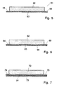
- FIG. 5 shows an embodiment of an insulating material 51 shown, which consists of an insulating sheet 52 and a Carrier web 53 exists.
- the two lanes 52, 53 are off Sheep wool fibers made by needling into one intimate association.
- the Carrier sheet densifies more than the insulating sheet, whereby it has greater strength.
- the connection too between the carrier sheet and the insulating sheet is through brought about this needling.
- the carrier web 53 is pending both long sides over the insulating sheet 52 in front, whereby Stripes 54 and 55 have been created to nail the Insulating material, for example on rafters, are used.
- a carrier web 63 on its side facing away from an insulating sheet 62, with provided a cover sheet 66 made of paper is. It can be simple kraft paper, but it is also possible to use impregnated paper use, which can also serve as a vapor barrier.
- the Carrier web 63 is also in this embodiment both long sides over the insulating sheet 62 in front, whereby Stripes 64 and 65 arise.
- the exemplary embodiment according to FIG Insulating material from an insulating sheet 72, a carrier sheet 73 and a cover sheet 77, which has a multilayer structure is.
- this can be done for the individual Layers of cover sheet 77 different materials be used.
- the use of Aluminum foil or plastic foil conceivable, both for example in combination with a thin layer of paper.
- Through the carrier web projecting over the insulating web 72 73 also result in stripes in this embodiment 74 or 75 for nailing the insulation material.
Landscapes
- Engineering & Computer Science (AREA)
- Textile Engineering (AREA)
- Mechanical Engineering (AREA)
- Polymers With Sulfur, Phosphorus Or Metals In The Main Chain (AREA)
- Laminated Bodies (AREA)
- Insulating Bodies (AREA)
- Braking Arrangements (AREA)
- Nonwoven Fabrics (AREA)
Description
- Fig. 1
- eine schaubildliche Darstellung einer Isoliermatte, die aus zwei Lagen, nämlich einer Trägerbahn und der eigentlichen Isolierbahn aufgebaut ist,
- Fig. 2
- eine schaubildliche Darstellung einer aus drei Lagen aufgebauten Isoliermatte,
- Fig.3
- eine Ansicht einer Isoliermatte, die aus vier Lagen aufgebaut ist, nämlich der eigentlichen Isolierschicht, einer Trägerschicht, einer Wellpappenlage und einer Aluminiumfolie,
- Fig.4
- eine Ansicht einer zu einer Rolle aufgewickelten Isoliermatte, die neben der Isolierschicht eine Trägerschicht und eine diese abdeckende Aluminiumfolie aufweist,
- Fig. 5
- einen Querschnitt durch ein mit einer Trägerbahn versehenes Isoliermaterial,
- Fig. 6
- einen Querschnitt durch ein ähnliches Isoliermaterial wie nach Fig.5, wobei zusätzlich eine Abdeckbahn aus Papier angeordnet ist und
- Fig.7
- ein weiteres Ausführungsbeispiel mit einer mehrlagigen Abdeckbahn.
Claims (5)
- Isoliermaterial, das einseitig mit einer Trägerbahn(3,23,33,43,53,63,73) versehen ist und aus einer Vielzahl von Fasern aus Schafwolle besteht, dadurch gekennzeichnet, daß die Fasern durch Eindrücken von Nadeln wenigstens geringfügig miteinander verbunden sind, und daß die Trägerbahn(3,23,33,43,53,63,73) ebenfalls aus Schafwolle-Fasern hergestellt und beim Vernadeln höher verdichtet ist als die eigentliche Isolierbahn(2,22,32,42,52,62,72), und daß die beiden Bahnen(2,22,32,42,52,62,72;3,23,33,43,53,63,73) durch das die eigentliche Isolierbahn(2,22,32,42,52,62,72) verfestigende Vernadeln miteinander verbunden sind.
- Isoliermaterial nach Anspruch 1, dadurch gekennzeichnet, daß die Trägerbahn(53,63,73) an ihren beiden Längsrändern wenigstens geringfügig über die eigentliche Isolierbahn(52,62,72) vorsteht.
- Isoliennaterial nach Anspruch 1 oder 2, dadurch gekennzeichnet, daß die eigentliche Isolierbahn (2,22,32,42,52,62,72) aus mehreren dünneren Teilbahnen(22,24) aufgebaut ist, welche miteinander vernadelt sind.
- Isoliermaterial nach einem der vorhergehenden Ansprüche, dadurch gekennzeichnet, daß die Trägerbahn(3,23,33,43,53,63,73) zusätzlich mit einer weiteren, auf der von der Isolierbahn(2,22,32,42,52,62,72) abgekehrten Seite angebrachten Abdeckbahn(66,77) versehen ist.
- Isoliermaterial nach Anspruch 4, dadurch gekennzeichnet, daß die Abdeckbahn(66) aus Papier od.dgl. besteht.
Applications Claiming Priority (4)
| Application Number | Priority Date | Filing Date | Title |
|---|---|---|---|
| DE4300815 | 1993-01-14 | ||
| DE19934300815 DE4300815A1 (de) | 1993-01-14 | 1993-01-14 | Isoliermaterial |
| DE4311195 | 1993-04-05 | ||
| DE4311195A DE4311195A1 (de) | 1993-01-14 | 1993-04-05 | Isoliermaterial |
Publications (2)
| Publication Number | Publication Date |
|---|---|
| EP0606844A1 EP0606844A1 (de) | 1994-07-20 |
| EP0606844B1 true EP0606844B1 (de) | 1999-04-07 |
Family
ID=25922265
Family Applications (1)
| Application Number | Title | Priority Date | Filing Date |
|---|---|---|---|
| EP94100086A Expired - Lifetime EP0606844B1 (de) | 1993-01-14 | 1994-01-05 | Isoliermaterial |
Country Status (6)
| Country | Link |
|---|---|
| EP (1) | EP0606844B1 (de) |
| AT (1) | ATE178668T1 (de) |
| DE (2) | DE4311195A1 (de) |
| DK (1) | DK0606844T3 (de) |
| ES (1) | ES2131592T3 (de) |
| GR (1) | GR3030292T3 (de) |
Families Citing this family (5)
| Publication number | Priority date | Publication date | Assignee | Title |
|---|---|---|---|---|
| DE19504166A1 (de) * | 1995-02-08 | 1996-08-14 | Neue Baumwollspinnerei & Weber | Vorrichtung zur bereichsweisen thermischen Isolierung von Kulturflächen, insbesondere Mulchmatte |
| DE29517006U1 (de) * | 1995-10-27 | 1996-03-07 | König, Joachim, 84494 Niederbergkirchen | Isolier-Schalen aus Schaf-Wolle |
| EP0884413A1 (de) * | 1997-06-13 | 1998-12-16 | Bonded Fibre Fabric Limited | Vliesstoff |
| DE10163576B4 (de) * | 2001-12-21 | 2006-07-20 | Sandler Ag | Isolations-Material |
| DE10234154B4 (de) * | 2002-07-26 | 2007-02-08 | Schulz, Eva Maria | Trägerband mit Dämmelement für Profilrahmenkonstruktionen |
Family Cites Families (5)
| Publication number | Priority date | Publication date | Assignee | Title |
|---|---|---|---|---|
| FR1315688A (fr) * | 1961-02-25 | 1963-01-18 | Bayerische Wollfilzfabrik K G | Procédé pour la fabrication d'un feutre avec garniture supérieure ou inférieure de tissu |
| DE1660755B2 (de) * | 1961-02-25 | 1976-03-11 | Bayerische Wollfilzfabriken KG, Offermann, Zeiler, Schmid & Co, Offingen und Hof, 8875 Offingen | Unterkragenmaterial |
| CH376636A (de) * | 1963-08-20 | 1964-04-15 | Brevetex S A | Isoliermatte, insbesondere zur Schallisolation |
| FR2207207A1 (en) * | 1972-11-22 | 1974-06-14 | Amyot Louis | Non-woven felt fabric having wool surface - formed by needling wool fibres to non-woven support and filling |
| DE2441527A1 (de) * | 1974-08-30 | 1976-03-11 | Gerhard Pohl | Verbundstoffstueck |
-
1993
- 1993-04-05 DE DE4311195A patent/DE4311195A1/de not_active Withdrawn
-
1994
- 1994-01-05 ES ES94100086T patent/ES2131592T3/es not_active Expired - Lifetime
- 1994-01-05 EP EP94100086A patent/EP0606844B1/de not_active Expired - Lifetime
- 1994-01-05 DK DK94100086T patent/DK0606844T3/da active
- 1994-01-05 DE DE59408051T patent/DE59408051D1/de not_active Expired - Fee Related
- 1994-01-05 AT AT94100086T patent/ATE178668T1/de not_active IP Right Cessation
-
1999
- 1999-05-20 GR GR990401378T patent/GR3030292T3/el unknown
Also Published As
| Publication number | Publication date |
|---|---|
| GR3030292T3 (en) | 1999-09-30 |
| DE4311195A1 (de) | 1994-10-06 |
| ES2131592T3 (es) | 1999-08-01 |
| DK0606844T3 (da) | 1999-10-18 |
| ATE178668T1 (de) | 1999-04-15 |
| EP0606844A1 (de) | 1994-07-20 |
| DE59408051D1 (de) | 1999-05-12 |
Similar Documents
| Publication | Publication Date | Title |
|---|---|---|
| EP0218108B1 (de) | Fussbodenbelag | |
| DE4108110C3 (de) | Wärmedämmaterial für Gebäude | |
| DE202016100525U1 (de) | Schallabsorptionslement | |
| DE10041481B4 (de) | Dämmstoffelement sowie Verfahren und Vorrichtung zur Herstellung eines Dämmstoffelementes, insbesondere einer roll- und/oder wickelbaren Dämmstoffbahn aus Mineralfasern | |
| DE69313306T2 (de) | Dämpfungsplatte mit einer eine geringe reibung aufweisenden oberfläche | |
| DE102020114155A1 (de) | Plattenförmiges Akustikelement | |
| EP3055130A1 (de) | Elastische bodenplatte | |
| EP0606844B1 (de) | Isoliermaterial | |
| DE4308959C2 (de) | Verwendung eines Vliesstoffes aus natürlichen Materialien | |
| DE3403386A1 (de) | Trittschalldaemmaterial | |
| EP0992340A2 (de) | Mehrschichtige Schalldämmplatte | |
| DE4223614C2 (de) | Dämmstoff sowie Verfahren zu seiner Herstellung | |
| DE3519752A1 (de) | Mineralfaserprodukt als daemmplatte oder daemmbahn | |
| DE3136935C1 (de) | Bahn oder Platte aus Mineralwolle, insbesondere Steinwolle | |
| DE3922028C2 (de) | ||
| DE19734532C2 (de) | Dämmelement | |
| DE102006028841B4 (de) | Dämmanordnung und Verfahren zur Herstellung eines Dämmstoffstreifens | |
| EP0269989A1 (de) | Bitumen-Abdichtbahn | |
| DE3643480A1 (de) | Schallabsorbierende wand- oder deckenverkleidung | |
| DE102005044051A1 (de) | Gebäudedach sowie Dämmschichtaufbau und Mineralfaserdämmstoffelement für ein Gebäudedach | |
| DE4300815A1 (de) | Isoliermaterial | |
| DE1070364B (de) | Mit einem Putzträger verbundene Mineralfaserdämmplatte | |
| EP0591658A1 (de) | Wärmedämmelement und Verfahren zu dessen Herstellung | |
| EP0894909B1 (de) | Dämmelement in Verbundausführung | |
| EP1122373B1 (de) | Verfahren zur Herstellung eines Dämmaterials aus Mineralfasern |
Legal Events
| Date | Code | Title | Description |
|---|---|---|---|
| PUAI | Public reference made under article 153(3) epc to a published international application that has entered the european phase |
Free format text: ORIGINAL CODE: 0009012 |
|
| AK | Designated contracting states |
Kind code of ref document: A1 Designated state(s): AT BE CH DE DK ES FR GB GR IE IT LI LU MC NL PT SE |
|
| 17P | Request for examination filed |
Effective date: 19940928 |
|
| 17Q | First examination report despatched |
Effective date: 19961016 |
|
| GRAG | Despatch of communication of intention to grant |
Free format text: ORIGINAL CODE: EPIDOS AGRA |
|
| GRAG | Despatch of communication of intention to grant |
Free format text: ORIGINAL CODE: EPIDOS AGRA |
|
| GRAH | Despatch of communication of intention to grant a patent |
Free format text: ORIGINAL CODE: EPIDOS IGRA |
|
| GRAH | Despatch of communication of intention to grant a patent |
Free format text: ORIGINAL CODE: EPIDOS IGRA |
|
| GRAA | (expected) grant |
Free format text: ORIGINAL CODE: 0009210 |
|
| AK | Designated contracting states |
Kind code of ref document: B1 Designated state(s): AT BE CH DE DK ES FR GB GR IE IT LI LU MC NL PT SE |
|
| REF | Corresponds to: |
Ref document number: 178668 Country of ref document: AT Date of ref document: 19990415 Kind code of ref document: T |
|
| REG | Reference to a national code |
Ref country code: CH Ref legal event code: EP |
|
| ITF | It: translation for a ep patent filed | ||
| REG | Reference to a national code |
Ref country code: IE Ref legal event code: FG4D Free format text: GERMAN |
|
| REF | Corresponds to: |
Ref document number: 59408051 Country of ref document: DE Date of ref document: 19990512 |
|
| ET | Fr: translation filed | ||
| GBT | Gb: translation of ep patent filed (gb section 77(6)(a)/1977) |
Effective date: 19990505 |
|
| REG | Reference to a national code |
Ref country code: CH Ref legal event code: NV Representative=s name: AMMANN PATENTANWAELTE AG BERN |
|
| REG | Reference to a national code |
Ref country code: ES Ref legal event code: FG2A Ref document number: 2131592 Country of ref document: ES Kind code of ref document: T3 |
|
| REG | Reference to a national code |
Ref country code: PT Ref legal event code: SC4A Free format text: AVAILABILITY OF NATIONAL TRANSLATION Effective date: 19990512 |
|
| REG | Reference to a national code |
Ref country code: DK Ref legal event code: T3 |
|
| PLBE | No opposition filed within time limit |
Free format text: ORIGINAL CODE: 0009261 |
|
| STAA | Information on the status of an ep patent application or granted ep patent |
Free format text: STATUS: NO OPPOSITION FILED WITHIN TIME LIMIT |
|
| 26N | No opposition filed | ||
| REG | Reference to a national code |
Ref country code: GB Ref legal event code: IF02 |
|
| PGFP | Annual fee paid to national office [announced via postgrant information from national office to epo] |
Ref country code: GR Payment date: 20021025 Year of fee payment: 10 |
|
| PGFP | Annual fee paid to national office [announced via postgrant information from national office to epo] |
Ref country code: IE Payment date: 20021112 Year of fee payment: 10 |
|
| PGFP | Annual fee paid to national office [announced via postgrant information from national office to epo] |
Ref country code: PT Payment date: 20021122 Year of fee payment: 10 |
|
| PGFP | Annual fee paid to national office [announced via postgrant information from national office to epo] |
Ref country code: LU Payment date: 20021203 Year of fee payment: 10 |
|
| PGFP | Annual fee paid to national office [announced via postgrant information from national office to epo] |
Ref country code: BE Payment date: 20021209 Year of fee payment: 10 |
|
| PGFP | Annual fee paid to national office [announced via postgrant information from national office to epo] |
Ref country code: GB Payment date: 20030108 Year of fee payment: 10 |
|
| PGFP | Annual fee paid to national office [announced via postgrant information from national office to epo] |
Ref country code: DK Payment date: 20030109 Year of fee payment: 10 |
|
| PGFP | Annual fee paid to national office [announced via postgrant information from national office to epo] |
Ref country code: FR Payment date: 20030116 Year of fee payment: 10 Ref country code: ES Payment date: 20030116 Year of fee payment: 10 |
|
| PGFP | Annual fee paid to national office [announced via postgrant information from national office to epo] |
Ref country code: SE Payment date: 20030128 Year of fee payment: 10 Ref country code: MC Payment date: 20030128 Year of fee payment: 10 |
|
| PGFP | Annual fee paid to national office [announced via postgrant information from national office to epo] |
Ref country code: NL Payment date: 20030225 Year of fee payment: 10 Ref country code: AT Payment date: 20030225 Year of fee payment: 10 |
|
| PGFP | Annual fee paid to national office [announced via postgrant information from national office to epo] |
Ref country code: CH Payment date: 20030226 Year of fee payment: 10 |
|
| PGFP | Annual fee paid to national office [announced via postgrant information from national office to epo] |
Ref country code: DE Payment date: 20030317 Year of fee payment: 10 |
|
| PG25 | Lapsed in a contracting state [announced via postgrant information from national office to epo] |
Ref country code: LU Free format text: LAPSE BECAUSE OF NON-PAYMENT OF DUE FEES Effective date: 20040105 Ref country code: IE Free format text: LAPSE BECAUSE OF NON-PAYMENT OF DUE FEES Effective date: 20040105 Ref country code: GB Free format text: LAPSE BECAUSE OF NON-PAYMENT OF DUE FEES Effective date: 20040105 Ref country code: AT Free format text: LAPSE BECAUSE OF NON-PAYMENT OF DUE FEES Effective date: 20040105 |
|
| PG25 | Lapsed in a contracting state [announced via postgrant information from national office to epo] |
Ref country code: SE Free format text: LAPSE BECAUSE OF NON-PAYMENT OF DUE FEES Effective date: 20040106 |
|
| PG25 | Lapsed in a contracting state [announced via postgrant information from national office to epo] |
Ref country code: ES Free format text: LAPSE BECAUSE OF NON-PAYMENT OF DUE FEES Effective date: 20040107 |
|
| PG25 | Lapsed in a contracting state [announced via postgrant information from national office to epo] |
Ref country code: MC Free format text: LAPSE BECAUSE OF NON-PAYMENT OF DUE FEES Effective date: 20040131 Ref country code: LI Free format text: LAPSE BECAUSE OF NON-PAYMENT OF DUE FEES Effective date: 20040131 Ref country code: CH Free format text: LAPSE BECAUSE OF NON-PAYMENT OF DUE FEES Effective date: 20040131 Ref country code: BE Free format text: LAPSE BECAUSE OF NON-PAYMENT OF DUE FEES Effective date: 20040131 |
|
| PG25 | Lapsed in a contracting state [announced via postgrant information from national office to epo] |
Ref country code: DK Free format text: LAPSE BECAUSE OF NON-PAYMENT OF DUE FEES Effective date: 20040202 |
|
| BERE | Be: lapsed |
Owner name: *DOPPELMAYER FRITZ Effective date: 20040131 |
|
| PG25 | Lapsed in a contracting state [announced via postgrant information from national office to epo] |
Ref country code: PT Free format text: LAPSE BECAUSE OF NON-PAYMENT OF DUE FEES Effective date: 20040731 |
|
| PG25 | Lapsed in a contracting state [announced via postgrant information from national office to epo] |
Ref country code: NL Free format text: LAPSE BECAUSE OF NON-PAYMENT OF DUE FEES Effective date: 20040801 |
|
| PG25 | Lapsed in a contracting state [announced via postgrant information from national office to epo] |
Ref country code: DE Free format text: LAPSE BECAUSE OF NON-PAYMENT OF DUE FEES Effective date: 20040803 |
|
| PG25 | Lapsed in a contracting state [announced via postgrant information from national office to epo] |
Ref country code: GR Free format text: LAPSE BECAUSE OF NON-PAYMENT OF DUE FEES Effective date: 20040804 |
|
| GBPC | Gb: european patent ceased through non-payment of renewal fee |
Effective date: 20040105 |
|
| EUG | Se: european patent has lapsed | ||
| REG | Reference to a national code |
Ref country code: DK Ref legal event code: EBP |
|
| REG | Reference to a national code |
Ref country code: CH Ref legal event code: PL |
|
| PG25 | Lapsed in a contracting state [announced via postgrant information from national office to epo] |
Ref country code: FR Free format text: LAPSE BECAUSE OF NON-PAYMENT OF DUE FEES Effective date: 20040930 |
|
| NLV4 | Nl: lapsed or anulled due to non-payment of the annual fee |
Effective date: 20040801 |
|
| REG | Reference to a national code |
Ref country code: IE Ref legal event code: MM4A |
|
| REG | Reference to a national code |
Ref country code: FR Ref legal event code: ST |
|
| PG25 | Lapsed in a contracting state [announced via postgrant information from national office to epo] |
Ref country code: IT Free format text: LAPSE BECAUSE OF NON-PAYMENT OF DUE FEES Effective date: 20050105 |
|
| REG | Reference to a national code |
Ref country code: ES Ref legal event code: FD2A Effective date: 20040107 |