EP0604331B1 - Abschliessvorrichtung mit Vorhängeschloss eines Handbetätigungshebels eines modularen elektrischen Schaltgerätes - Google Patents
Abschliessvorrichtung mit Vorhängeschloss eines Handbetätigungshebels eines modularen elektrischen Schaltgerätes Download PDFInfo
- Publication number
- EP0604331B1 EP0604331B1 EP93420496A EP93420496A EP0604331B1 EP 0604331 B1 EP0604331 B1 EP 0604331B1 EP 93420496 A EP93420496 A EP 93420496A EP 93420496 A EP93420496 A EP 93420496A EP 0604331 B1 EP0604331 B1 EP 0604331B1
- Authority
- EP
- European Patent Office
- Prior art keywords
- lever
- handle
- stable positions
- padlocking
- cover
- Prior art date
- Legal status (The legal status is an assumption and is not a legal conclusion. Google has not performed a legal analysis and makes no representation as to the accuracy of the status listed.)
- Expired - Lifetime
Links
- 230000009975 flexible effect Effects 0.000 claims abstract description 14
- 238000007789 sealing Methods 0.000 claims description 13
- 230000002441 reversible effect Effects 0.000 claims description 2
- 230000000087 stabilizing effect Effects 0.000 description 5
- 230000000903 blocking effect Effects 0.000 description 4
- 125000006850 spacer group Chemical group 0.000 description 4
- 210000004027 cell Anatomy 0.000 description 2
- 230000000694 effects Effects 0.000 description 2
- 241000287107 Passer Species 0.000 description 1
- 229910000831 Steel Inorganic materials 0.000 description 1
- 238000002347 injection Methods 0.000 description 1
- 239000007924 injection Substances 0.000 description 1
- 239000010959 steel Substances 0.000 description 1
- 229920002994 synthetic fiber Polymers 0.000 description 1
Images


Classifications
-
- H—ELECTRICITY
- H01—ELECTRIC ELEMENTS
- H01H—ELECTRIC SWITCHES; RELAYS; SELECTORS; EMERGENCY PROTECTIVE DEVICES
- H01H9/00—Details of switching devices, not covered by groups H01H1/00 - H01H7/00
- H01H9/20—Interlocking, locking, or latching mechanisms
- H01H9/28—Interlocking, locking, or latching mechanisms for locking switch parts by a key or equivalent removable member
- H01H9/281—Interlocking, locking, or latching mechanisms for locking switch parts by a key or equivalent removable member making use of a padlock
- H01H9/282—Interlocking, locking, or latching mechanisms for locking switch parts by a key or equivalent removable member making use of a padlock and a separate part mounted or mountable on the switch assembly and movable between an unlocking position and a locking position where it can be secured by the padlock
- H01H9/283—Interlocking, locking, or latching mechanisms for locking switch parts by a key or equivalent removable member making use of a padlock and a separate part mounted or mountable on the switch assembly and movable between an unlocking position and a locking position where it can be secured by the padlock the part being removable
Definitions
- a lockout device is equipped with a locking pin whose flexible arms are associated with lugs arranged to penetrate the sealing holes in the circuit breaker box.
- the two arms are connected by a handle in which a padlock can be inserted which immobilizes a slide arranged to block the lugs in the sealing holes and thus maintain the release lever in one of its stable positions.
- This slide is a relatively fragile piece and does not guarantee absolute inviolability of the system.
- the present invention proposes to overcome the drawbacks of known devices by providing maximum security by guaranteeing that the manual control lever of an electrical appliance cannot be moved accidentally when it has been intentionally blocked in one of its stable positions.
- said spacer is secured to the lever, and is disposed between the flexible arms.
- the cover of the device preferably includes a cavity in which the handle can be housed when it is in one of its stable positions. The device is advantageously reversible depending on whether the lever occupies one or the other of its two stable positions.
- the lever is provided with a pusher, and the cover is closed when the lever is in its low position.
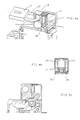
- the padlocking device 10 is provided to be adapted over the manual control lever 11 of a modular electrical device such as a circuit breaker 12.
- a modular electrical device such as a circuit breaker 12.
- this lever is tilted in one or other of its stable positions, namely in its open position (see Figure 1) or in its closed position (see Figure 2) the padlocking device is positioned in one direction or in the opposite direction.
- the blocking of the lever and the padlocking of the device when this blocking is accomplished, can only be achieved if the lever is actually in one of its stable positions and are prohibited if it is in a position intermediate.
- the device comprises, as shown more particularly in FIGS. 3A, 3B, 3C; 4A, 4B, 4C and 5A, 5B, 5C, a cover 13 comprising a cavity 14 in which the manual control lever 11 can be housed, a lever 15 movable between a first unlocked position (see FIGS. 3A, B and C) and a second locked position (see FIGS. 4A, B and C), and a locking pin 16 mounted in a housing disposed between the cavity 14 and the lever 11.
- the lever 15 is equipped with a pusher 17 which allows the user to move it from its high position, called the first unlocked position, to its low position, called the second locked position, and vice versa. It also comprises an opening 18 whose dimensions are substantially equal to those of at least one opening 19 formed through the cover, so that when the lever is brought into its low position (see FIGS. 4A, B and C ), the openings 18 and 19 are located opposite one another and it becomes possible to padlock the device by passing the handle 20 of a padlock 21 in these openings.
- the cover comprises two parallel wall elements 22 and 23 (see FIG. 2) each provided with an opening 19, and the lever 15 is arranged to be able to slide between these elements which serve as guides when 'it is moved between its two positions defined above.
- the lever also includes a spacer 24 (see Figures 3B, 4B and 5B) whose role will be described below.
- the manual control lever 11 is integral with a drum 25, rotatable about an axis integral with the housing of the electrical appliance, and which comprises, in a manner known per se, two sealing holes 26.
- the pin locking which is shown in more detail and enlarged by Figure 6, comprises a central element 27 in the shape of a U, the two branches 27a and 27b of which are respectively extended by two lateral arms 28a and 28b carrying at their ends two lugs 29a and 29b. These two pins are arranged to engage respectively in the two sealing holes 26, when on the one hand the lever 11 is in one of its stable positions and on the other hand, when the pusher 17 is brought into its position low. In this position, the spacer 24 mentioned above, which was initially (see fig.
- FIGS. 5A, 5B and 5C illustrate a particular case where the lever 11 is accidentally in an intermediate position between its stable positions.
- the central element 27 of the locking pin is in fact locked in a space 30 in such a way that it has a certain play. It plays the role of a feeler capable of detecting the intermediate position of the lever 11.
- the central element 27 or feeler abuts against this lever when the padlocking device is put in place, which has the effect of tilting the pin. Because of this inclination, the pins 29a and 29b are no longer in front of the sealing holes and therefore cannot engage in these holes when the pusher 17 is lowered.
- the pin feeler constitutes a fault detector which prevents locking of the lever and blocking of the padlocking device if said lever does not occupy one of its two stable positions.
- the cover 13 and the lever 15 are preferably made of injection molded synthetic material.
- the pin is preferably made of steel. Their shape and dimensions can be adapted to the geometry of the electrical devices concerned. It should be noted that the cover is fully closed when the pusher is pressed, the lever being in its low position, making access to the pin 16 impossible.
Landscapes
- Breakers (AREA)
- Switch Cases, Indication, And Locking (AREA)
- Driving Mechanisms And Operating Circuits Of Arc-Extinguishing High-Tension Switches (AREA)
- Switches With Compound Operations (AREA)
- Mechanical Control Devices (AREA)
Claims (6)
- Verriegelungsvorrichtung (10) für einen Schaltknebel (11) zur Handbetätigung eines modularen elektrischen Schaltgeräts, insbesondere eines Leistungsschalters (12), bei dem der Schaltknebel (11) zwei stabile Stellungen entsprechend der Einschaltstellung und der Ausschaltstellung des Schaltgeräts einnehmen kann, wobei das Gehäuse des Schaltgeräts (12) mit Plombieröffnungen (26) versehen ist und die Verriegelungsvorrichtung (10) folgende Teile umfaßt:- eine Verriegelungsklammer (16) mit zwei Federarmen (28a, 28b), an denen Ansätze (29a, 29b) zum Eingreifen in die Plombieröffnungen (26) ausgebildet sind, wenn der genannte Schaltknebel (11) in einer seiner stabilen Stellungen steht, wobei die Verriegelungsvorrichtung so ausgebildet ist, daß sie an das Gehäuse angebaut werden kann, wenn der Schaltknebel (11) in der einen oder anderen seiner stabilen Stellungen steht,- ein Tastelement zur Erfassung einer Zwischenstellung zwischen den genannten stabilen Stellungen des Schaltknebels (11) sowie zur Verhinderung der Verriegelung in dieser Stellung,- einen zwischen einer ersten, oberen Stellung und einer zweiten, unteren Stellung verschiebbaren beweglichen Hebel (15), welcher Hebel (15) eine erste Öffnung (18) aufweist, die das Hindurchführen eines Vorhängeschlosses (21) zur Verriegelung ermöglicht, wenn der Hebel (15) in die zweite Stellung verbracht ist, sowie- ein Spreizelement (24) des genannten Hebels (15), das dazu dient, die Federarme (28a, 28b) auseinanderzudrücken, wenn der Hebel (15) von der ersten Stellung in die zweite Stellung verbracht wird, und die Ansätze (29a, 29b) in die genannten Plombieröffnungen (26) einzuschieben,dadurch gekennzeichnet ist, daß- der Hebel (15) in einem Aufsatz (13) gelagert ist, der eine zweite Öffnung (19) aufweist, welche mit der ersten Öffnung (18) fluchtet, wenn der Hebel (15) in der zweiten Stellung steht, und zur Durchführung des Vorhängeschlosses (21) dient,- die Verriegelungsklammer (16) im Aufsatz (13) gelagert ist und einen, das genannte Tastelement bildenden, U-förmigen Mittelteil umfaßt, wobei die Schenkel (27a, 27b) des U durch die genannten Federarme (28a, 28b) verlängert sind, an deren Enden die genannten Ansätze (29a, 29b) ausgebildet sind,- eine Aufnahme der genannten Klammer (16) ein Spiel aufweist, das ausreichend groß ist, um der Klammer die Einnahme eine mehr oder weniger geneigten Stellung zu ermöglichen, wenn der Schaltknebel (11) in einer anderen als einer seiner beiden stabilen Stellungen steht.
- Vorrichtung nach Anspruch 1, dadurch gekennzeichnet, daß das genannte Spreizelement (24) fest mit dem Hebel (15) verbunden und zwischen den Federarmen (28a, 28b) angeordnet ist.
- Vorrichtung nach Anspruch 1, dadurch gekennzeichnet, daß der Aufsatz (13) eine Ausnehmung (14) aufweist, in die der Schaltknebel (11) eingeführt werden kann, wenn er in einer seiner stabilen Stellungen steht.
- Vorrichtung nach Anspruch 3, dadurch gekennzeichnet, daß sie umgedreht werden kann, um in beiden stabilen Stellungen des Schaltknebels (11) aufgesetzt werden zu können.
- Vorrichtung nach Anspruch 1, dadurch gekennzeichnet, daß der Hebel (15) eine Druckplatte (17) aufweist.
- Vorrichtung nach Anspruch 5, dadurch gekennzeichnet, daß der Aufsatz (13) in der abgesenkten Stellung des Hebels (15) geschlossen ist.
Applications Claiming Priority (2)
| Application Number | Priority Date | Filing Date | Title |
|---|---|---|---|
| FR9215580A FR2699728B1 (fr) | 1992-12-21 | 1992-12-21 | Dispositif de cadenassage d'une manette de commande manuelle d'un appareil électrique modulaire. |
| FR9215580 | 1992-12-21 |
Publications (2)
| Publication Number | Publication Date |
|---|---|
| EP0604331A1 EP0604331A1 (de) | 1994-06-29 |
| EP0604331B1 true EP0604331B1 (de) | 1997-08-06 |
Family
ID=9437006
Family Applications (1)
| Application Number | Title | Priority Date | Filing Date |
|---|---|---|---|
| EP93420496A Expired - Lifetime EP0604331B1 (de) | 1992-12-21 | 1993-12-13 | Abschliessvorrichtung mit Vorhängeschloss eines Handbetätigungshebels eines modularen elektrischen Schaltgerätes |
Country Status (5)
| Country | Link |
|---|---|
| EP (1) | EP0604331B1 (de) |
| AT (1) | ATE156628T1 (de) |
| DE (1) | DE69312892T2 (de) |
| ES (1) | ES2106993T3 (de) |
| FR (1) | FR2699728B1 (de) |
Cited By (1)
| Publication number | Priority date | Publication date | Assignee | Title |
|---|---|---|---|---|
| EP2388790A1 (de) | 2010-05-19 | 2011-11-23 | Eaton Industries GmbH | Leistungsschalter mit Abschliessvorrichtung |
Families Citing this family (11)
| Publication number | Priority date | Publication date | Assignee | Title |
|---|---|---|---|---|
| DE19917859A1 (de) * | 1999-04-20 | 2000-10-26 | Siemens Ag | Sperrvorrichtung für Schaltgeräte |
| FR2801687B1 (fr) | 1999-11-29 | 2002-01-11 | Eastman Kodak Co | Procede d'enregistrement cinematographique et dispositif pour diminuer les defauts d'enregistrement |
| JP3893824B2 (ja) * | 1999-12-27 | 2007-03-14 | 松下電器産業株式会社 | レバースイッチ及びこれを用いた検出装置 |
| US6476698B1 (en) * | 2000-03-17 | 2002-11-05 | General Electric Company | Convertible locking arrangement on breakers |
| WO2002077901A2 (en) * | 2001-03-21 | 2002-10-03 | Brady Worldwide, Inc. | Circuit breaker lock-out assembly |
| DE20304414U1 (de) * | 2003-03-19 | 2004-07-29 | Weidmüller Interface Gmbh & Co. | Schaltgerät mit Anschlüssen für elektrische Leiter |
| DE102009017059B3 (de) * | 2009-04-09 | 2010-07-08 | Siemens Aktiengesellschaft | Anordnung zur Blockierung eines Betätigungselements eines Elektroinstallationsgeräts sowie Elektroinstallationsgerät |
| GB0919366D0 (en) * | 2009-11-05 | 2009-12-23 | Schneider Electric Ltd | Safety device for electrical distribution boards |
| CN108511292B (zh) * | 2017-02-24 | 2019-12-31 | 上海良信电器股份有限公司 | 电动操作装置的挂锁机构 |
| CN112509889B (zh) * | 2020-12-21 | 2025-03-11 | 浙江俊朗电气自动化股份有限公司 | 塑壳断路器手柄锁定装置 |
| FR3121546A1 (fr) * | 2021-03-30 | 2022-10-07 | Schneider Electric Industries Sas | Système de verrouillage pour disjoncteur |
Family Cites Families (4)
| Publication number | Priority date | Publication date | Assignee | Title |
|---|---|---|---|---|
| FR2412154A1 (fr) * | 1977-12-15 | 1979-07-13 | Merlin Gerin | Dispositif de cadenassage de la manette d'un disjoncteur miniature |
| FR2424619A1 (fr) * | 1978-04-24 | 1979-11-23 | Merlin Gerin | Dispositif de cadenassage d'une manette d'un disjoncteur electrique |
| GB2152286A (en) * | 1983-12-23 | 1985-07-31 | Midland Electric Mfg Co Ltd | Switch locking device |
| FR2569046B1 (fr) * | 1984-08-08 | 1986-11-28 | Merlin Gerin | Dispositif de cadenassage d'un disjoncteur miniature |
-
1992
- 1992-12-21 FR FR9215580A patent/FR2699728B1/fr not_active Expired - Fee Related
-
1993
- 1993-12-13 ES ES93420496T patent/ES2106993T3/es not_active Expired - Lifetime
- 1993-12-13 DE DE69312892T patent/DE69312892T2/de not_active Expired - Fee Related
- 1993-12-13 AT AT93420496T patent/ATE156628T1/de not_active IP Right Cessation
- 1993-12-13 EP EP93420496A patent/EP0604331B1/de not_active Expired - Lifetime
Cited By (3)
| Publication number | Priority date | Publication date | Assignee | Title |
|---|---|---|---|---|
| EP2388790A1 (de) | 2010-05-19 | 2011-11-23 | Eaton Industries GmbH | Leistungsschalter mit Abschliessvorrichtung |
| DE102010020987A1 (de) | 2010-05-19 | 2011-11-24 | Eaton Industries Gmbh | Leistungsschalter mit Abschließvorrichtung |
| DE102010020987B4 (de) * | 2010-05-19 | 2012-04-05 | Eaton Industries Gmbh | Leistungsschalter mit Abschließvorrichtung |
Also Published As
| Publication number | Publication date |
|---|---|
| ES2106993T3 (es) | 1997-11-16 |
| EP0604331A1 (de) | 1994-06-29 |
| ATE156628T1 (de) | 1997-08-15 |
| FR2699728B1 (fr) | 1995-03-17 |
| DE69312892T2 (de) | 1998-01-29 |
| FR2699728A1 (fr) | 1994-06-24 |
| DE69312892D1 (de) | 1997-09-11 |
Similar Documents
| Publication | Publication Date | Title |
|---|---|---|
| EP0604331B1 (de) | Abschliessvorrichtung mit Vorhängeschloss eines Handbetätigungshebels eines modularen elektrischen Schaltgerätes | |
| EP0567416B1 (de) | Mechanische Verriegelungsvorrichtung von zwei Schaltern mit Isolierstoff-Formgehäuse | |
| EP0591074B1 (de) | Lastschalter mit gegossenem Gehäuse mit Hilfkontakten | |
| EP0610143A1 (de) | Mechanischer und elektrischer Verriegelungsvorrichtung eines Fernbedienungseinheits für moduläre Lastschalter | |
| FR2755533A1 (fr) | Interrupteur de securite a tete pivotante | |
| EP1729313B1 (de) | Antriebsvorrichtung eines elektischen Schaltgerätes mit Schaltsperre | |
| CH678905A5 (de) | ||
| EP0656148A1 (de) | Schutzschalter mit drehbar gelagerten betätigungsknöpfen. | |
| EP0612092B1 (de) | Schutzschalter mit anpassbarer Fernbetätigungseinheit | |
| FR2747230A1 (fr) | Bouton d'arret d'urgence cadenassable | |
| FR2513006A1 (fr) | Dispositif interrupteur modulaire a poles multiples | |
| FR2516699A1 (fr) | Structure pour disjoncteur comportant deux boitiers a commande manuelle | |
| FR2696042A1 (fr) | Appareil sectionneur associable à un disjoncteur. | |
| FR2684231A1 (fr) | Appareils auxiliaires de disjoncteurs electriques. | |
| EP0511043B1 (de) | Elektromechanischer Schalter mit Wendezusatzeinheit | |
| BE1004593A3 (fr) | Dispositif pour l'interdiction selective d'un ou plusieurs modes d'actionnement d'organes manuels de commande equipant un appareil. | |
| EP0575216B1 (de) | Verriegelungsvorrichtung für Lastschalter mit Klappdeckel | |
| FR2867895A1 (fr) | Dispositif de manoeuvre securise pour appareil de coupure electrique et appareil equipe d'un tel dispositif | |
| EP1180264A1 (de) | Betätigungsvorrichtung für schalter | |
| WO2022117751A1 (fr) | Dispositif de châssis pour appareil électrique de coupure débrochable et ensemble comprenant un tel dispositif et un tel appareil | |
| CH719478A2 (fr) | Serrure différentielle pour appareil électrique de protection différentielle et appareil électrique de protection différentielle. | |
| EP2811502A1 (de) | Elektrisches Sicherungsgerät umfassend eine Vorrichtung zur Verriegelung des Zugangs zu den Einstellmitteln des elektrischen Sicherungsgeräts | |
| FR2701592A1 (fr) | Dispositif de commande rotative d'un disjoncteur. | |
| FR2990292A1 (fr) | Disjoncteur a moyens de consignation ameliores | |
| FR2625030A1 (fr) | Commutateur incorporable dans une minuterie modulaire |
Legal Events
| Date | Code | Title | Description |
|---|---|---|---|
| PUAI | Public reference made under article 153(3) epc to a published international application that has entered the european phase |
Free format text: ORIGINAL CODE: 0009012 |
|
| AK | Designated contracting states |
Kind code of ref document: A1 Designated state(s): AT BE CH DE ES GB IT LI |
|
| 17P | Request for examination filed |
Effective date: 19941213 |
|
| RAP1 | Party data changed (applicant data changed or rights of an application transferred) |
Owner name: SCHNEIDER ELECTRIC SA |
|
| 17Q | First examination report despatched |
Effective date: 19960214 |
|
| GRAG | Despatch of communication of intention to grant |
Free format text: ORIGINAL CODE: EPIDOS AGRA |
|
| GRAH | Despatch of communication of intention to grant a patent |
Free format text: ORIGINAL CODE: EPIDOS IGRA |
|
| GRAH | Despatch of communication of intention to grant a patent |
Free format text: ORIGINAL CODE: EPIDOS IGRA |
|
| GRAA | (expected) grant |
Free format text: ORIGINAL CODE: 0009210 |
|
| AK | Designated contracting states |
Kind code of ref document: B1 Designated state(s): AT BE CH DE ES GB IT LI |
|
| PG25 | Lapsed in a contracting state [announced via postgrant information from national office to epo] |
Ref country code: AT Effective date: 19970806 |
|
| REF | Corresponds to: |
Ref document number: 156628 Country of ref document: AT Date of ref document: 19970815 Kind code of ref document: T |
|
| REG | Reference to a national code |
Ref country code: CH Ref legal event code: EP |
|
| REF | Corresponds to: |
Ref document number: 69312892 Country of ref document: DE Date of ref document: 19970911 |
|
| GBT | Gb: translation of ep patent filed (gb section 77(6)(a)/1977) |
Effective date: 19970919 |
|
| ITF | It: translation for a ep patent filed | ||
| REG | Reference to a national code |
Ref country code: ES Ref legal event code: FG2A Ref document number: 2106993 Country of ref document: ES Kind code of ref document: T3 |
|
| PG25 | Lapsed in a contracting state [announced via postgrant information from national office to epo] |
Ref country code: LI Free format text: LAPSE BECAUSE OF NON-PAYMENT OF DUE FEES Effective date: 19971231 Ref country code: CH Free format text: LAPSE BECAUSE OF NON-PAYMENT OF DUE FEES Effective date: 19971231 Ref country code: BE Free format text: LAPSE BECAUSE OF NON-PAYMENT OF DUE FEES Effective date: 19971231 |
|
| PLBE | No opposition filed within time limit |
Free format text: ORIGINAL CODE: 0009261 |
|
| STAA | Information on the status of an ep patent application or granted ep patent |
Free format text: STATUS: NO OPPOSITION FILED WITHIN TIME LIMIT |
|
| BERE | Be: lapsed |
Owner name: S.A. SCHNEIDER ELECTRIC Effective date: 19971231 |
|
| 26N | No opposition filed | ||
| REG | Reference to a national code |
Ref country code: CH Ref legal event code: PL |
|
| REG | Reference to a national code |
Ref country code: GB Ref legal event code: IF02 |
|
| PGFP | Annual fee paid to national office [announced via postgrant information from national office to epo] |
Ref country code: DE Payment date: 20021203 Year of fee payment: 10 |
|
| PGFP | Annual fee paid to national office [announced via postgrant information from national office to epo] |
Ref country code: GB Payment date: 20021211 Year of fee payment: 10 |
|
| PGFP | Annual fee paid to national office [announced via postgrant information from national office to epo] |
Ref country code: ES Payment date: 20030121 Year of fee payment: 10 |
|
| PG25 | Lapsed in a contracting state [announced via postgrant information from national office to epo] |
Ref country code: GB Free format text: LAPSE BECAUSE OF NON-PAYMENT OF DUE FEES Effective date: 20031213 |
|
| PG25 | Lapsed in a contracting state [announced via postgrant information from national office to epo] |
Ref country code: ES Free format text: LAPSE BECAUSE OF NON-PAYMENT OF DUE FEES Effective date: 20031215 |
|
| PG25 | Lapsed in a contracting state [announced via postgrant information from national office to epo] |
Ref country code: DE Free format text: LAPSE BECAUSE OF NON-PAYMENT OF DUE FEES Effective date: 20040701 |
|
| GBPC | Gb: european patent ceased through non-payment of renewal fee |
Effective date: 20031213 |
|
| REG | Reference to a national code |
Ref country code: ES Ref legal event code: FD2A Effective date: 20031215 |
|
| PG25 | Lapsed in a contracting state [announced via postgrant information from national office to epo] |
Ref country code: IT Free format text: LAPSE BECAUSE OF NON-PAYMENT OF DUE FEES;WARNING: LAPSES OF ITALIAN PATENTS WITH EFFECTIVE DATE BEFORE 2007 MAY HAVE OCCURRED AT ANY TIME BEFORE 2007. THE CORRECT EFFECTIVE DATE MAY BE DIFFERENT FROM THE ONE RECORDED. Effective date: 20051213 |