EP0604085B1 - Bremsvorrichtung für ein Fahrzeug mit Vierradantrieb - Google Patents
Bremsvorrichtung für ein Fahrzeug mit Vierradantrieb Download PDFInfo
- Publication number
- EP0604085B1 EP0604085B1 EP93310019A EP93310019A EP0604085B1 EP 0604085 B1 EP0604085 B1 EP 0604085B1 EP 93310019 A EP93310019 A EP 93310019A EP 93310019 A EP93310019 A EP 93310019A EP 0604085 B1 EP0604085 B1 EP 0604085B1
- Authority
- EP
- European Patent Office
- Prior art keywords
- wheel drive
- operated
- wheels
- braking facility
- drive clutch
- Prior art date
- Legal status (The legal status is an assumption and is not a legal conclusion. Google has not performed a legal analysis and makes no representation as to the accuracy of the status listed.)
- Expired - Lifetime
Links
- 239000012530 fluid Substances 0.000 claims description 9
- 230000000063 preceeding effect Effects 0.000 claims 1
- 230000000994 depressogenic effect Effects 0.000 description 1
- 238000010586 diagram Methods 0.000 description 1
Images
Classifications
-
- B—PERFORMING OPERATIONS; TRANSPORTING
- B60—VEHICLES IN GENERAL
- B60T—VEHICLE BRAKE CONTROL SYSTEMS OR PARTS THEREOF; BRAKE CONTROL SYSTEMS OR PARTS THEREOF, IN GENERAL; ARRANGEMENT OF BRAKING ELEMENTS ON VEHICLES IN GENERAL; PORTABLE DEVICES FOR PREVENTING UNWANTED MOVEMENT OF VEHICLES; VEHICLE MODIFICATIONS TO FACILITATE COOLING OF BRAKES
- B60T11/00—Transmitting braking action from initiating means to ultimate brake actuator without power assistance or drive or where such assistance or drive is irrelevant
- B60T11/10—Transmitting braking action from initiating means to ultimate brake actuator without power assistance or drive or where such assistance or drive is irrelevant transmitting by fluid means, e.g. hydraulic
- B60T11/103—Transmitting braking action from initiating means to ultimate brake actuator without power assistance or drive or where such assistance or drive is irrelevant transmitting by fluid means, e.g. hydraulic in combination with other control devices
-
- B—PERFORMING OPERATIONS; TRANSPORTING
- B60—VEHICLES IN GENERAL
- B60K—ARRANGEMENT OR MOUNTING OF PROPULSION UNITS OR OF TRANSMISSIONS IN VEHICLES; ARRANGEMENT OR MOUNTING OF PLURAL DIVERSE PRIME-MOVERS IN VEHICLES; AUXILIARY DRIVES FOR VEHICLES; INSTRUMENTATION OR DASHBOARDS FOR VEHICLES; ARRANGEMENTS IN CONNECTION WITH COOLING, AIR INTAKE, GAS EXHAUST OR FUEL SUPPLY OF PROPULSION UNITS IN VEHICLES
- B60K23/00—Arrangement or mounting of control devices for vehicle transmissions, or parts thereof, not otherwise provided for
- B60K23/08—Arrangement or mounting of control devices for vehicle transmissions, or parts thereof, not otherwise provided for for changing number of driven wheels, for switching from driving one axle to driving two or more axles
-
- B—PERFORMING OPERATIONS; TRANSPORTING
- B60—VEHICLES IN GENERAL
- B60W—CONJOINT CONTROL OF VEHICLE SUB-UNITS OF DIFFERENT TYPE OR DIFFERENT FUNCTION; CONTROL SYSTEMS SPECIALLY ADAPTED FOR HYBRID VEHICLES; ROAD VEHICLE DRIVE CONTROL SYSTEMS FOR PURPOSES NOT RELATED TO THE CONTROL OF A PARTICULAR SUB-UNIT
- B60W10/00—Conjoint control of vehicle sub-units of different type or different function
- B60W10/119—Conjoint control of vehicle sub-units of different type or different function including control of all-wheel-driveline means, e.g. transfer gears or clutches for dividing torque between front and rear axle
-
- B—PERFORMING OPERATIONS; TRANSPORTING
- B60—VEHICLES IN GENERAL
- B60W—CONJOINT CONTROL OF VEHICLE SUB-UNITS OF DIFFERENT TYPE OR DIFFERENT FUNCTION; CONTROL SYSTEMS SPECIALLY ADAPTED FOR HYBRID VEHICLES; ROAD VEHICLE DRIVE CONTROL SYSTEMS FOR PURPOSES NOT RELATED TO THE CONTROL OF A PARTICULAR SUB-UNIT
- B60W10/00—Conjoint control of vehicle sub-units of different type or different function
- B60W10/18—Conjoint control of vehicle sub-units of different type or different function including control of braking systems
- B60W10/184—Conjoint control of vehicle sub-units of different type or different function including control of braking systems with wheel brakes
-
- B—PERFORMING OPERATIONS; TRANSPORTING
- B60—VEHICLES IN GENERAL
- B60W—CONJOINT CONTROL OF VEHICLE SUB-UNITS OF DIFFERENT TYPE OR DIFFERENT FUNCTION; CONTROL SYSTEMS SPECIALLY ADAPTED FOR HYBRID VEHICLES; ROAD VEHICLE DRIVE CONTROL SYSTEMS FOR PURPOSES NOT RELATED TO THE CONTROL OF A PARTICULAR SUB-UNIT
- B60W30/00—Purposes of road vehicle drive control systems not related to the control of a particular sub-unit, e.g. of systems using conjoint control of vehicle sub-units
- B60W30/18—Propelling the vehicle
- B60W30/18009—Propelling the vehicle related to particular drive situations
- B60W30/18109—Braking
-
- B—PERFORMING OPERATIONS; TRANSPORTING
- B60—VEHICLES IN GENERAL
- B60W—CONJOINT CONTROL OF VEHICLE SUB-UNITS OF DIFFERENT TYPE OR DIFFERENT FUNCTION; CONTROL SYSTEMS SPECIALLY ADAPTED FOR HYBRID VEHICLES; ROAD VEHICLE DRIVE CONTROL SYSTEMS FOR PURPOSES NOT RELATED TO THE CONTROL OF A PARTICULAR SUB-UNIT
- B60W2510/00—Input parameters relating to a particular sub-units
- B60W2510/18—Braking system
- B60W2510/186—Status of parking brakes
Definitions
- This invention relates to four wheel drive vehicles and particularly, though not exclusively, to agricultural tractors.
- Relevant prior art is found in DE-A-3544288, on which the preamble of Claim 1 is based.
- a braking facility for a four wheel drive vehicle having front and rear axles with front and rear pairs of wheels, an engine driving the rear wheels and also connectable to the front wheels via a four wheel drive clutch, and left and right hand brakes on the rear axle operated by a main brake actuating system
- the braking facility including a hand brake lever which also operates the left and right rear brakes and sensing means associated with the hand brake lever and arranged to engage automatically the four wheel drive clutch when the hand brake is operated to provide a hand brake lever operated braking facility connected to all four wheels, characterised in that the four wheel drive clutch is a friction clutch and that the handbrake lever operates the rear brakes via a system independent from the main brake actuating system, whereby a handbrake operated braking facility connected to all four wheels is provided which is independent of the main brake operating system and which is operable when the vehicle is in motion.
- the operation of the four wheel drive clutch can be controlled using fluid pressure via a solenoid-operated fluid-flow control valve.
- the sensing means may comprise a switch which is operated on movement of the brake lever to operate the solenoid-operated valve.
- the clutch can be arranged to be engaged by spring means and released by the application of fluid pressure to an actuator. In such an arrangement any failure of the fluid pressure, or the switching off of the vehicle ignition, will result in engagement of the clutch and the inter-connection of all four wheels thus providing an added safety factor.
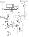
- the tractor has an engine E which drives a rear axle 10 with rear wheels W1 via main clutch C, a gearbox G and a rear axle differential D1.
- the engine E is also connectable to the front axle 11 of the tractor, which is provided with wheels W2 and the differential D2, via a four wheel drive clutch 12.
- Clutch 12 is of the multi-plate type and is normally held engaged by spring means shown diagrammatically at 13.
- the clutch is disengaged (as shown in the drawing) by an hydraulic actuator 14 which when pressurised via a solenoid-operated valve 15 acts against spring means 13 to disengage the four wheel drive clutch.
- Valve 15 is fed with pressurised fluid by a pump 16 which forms part of the normal hydraulic circuit of the tractor. The pump draws fluid from and returns fluid to a sump 17.
- the rear axle 10 is provided with a left-hand brake 18 and a right-hand brake 19 which are operated in a conventional tractor manner by separate left and right-hand brake pedals 20 and 21 respectively. These pedals can be joined together in a conventional manner for simultaneous operation of the brakes by a mechanical latch 22.
- lines 23 and 24 diagrammatically illustrate the operative connection between the pedals 20 and 21 and the associated respective brakes 18 and 19. It will be appreciated that in an actual system either separate master cylinders or a single tandem master cylinder will be operated by the pedals 20 and 21 and will generate the necessary hydraulic pressure to operate slave cylinders associated with the respective brakes. None of this detail is shown in Figure 1 since it is all conventional and well understood by those skilled in the art.
- the left and right-hand brakes 18 and 19 can also be applied mechanically by a hand brake lever 25, which is mechanically connected to the brakes by cables and rods or other mechanical means indicated diagrammatically by dotted lines 26 and 27 in the accompanying drawing.
- the operation of the hand brake lever (which is shown in the disengaged condition in the accompanying drawing) operates a double pole changeover switch 28 which has its contact 28a closed when the hand brake is not engaged thus energising the solenoid 15a of valve 15 via a series connected double pole rocker switch 29 and a single pole switch 30 operated by the brake pedals 20, 21.
- Energisation of solenoid 15a directs pressurised fluid to actuator 14 from pump 16, thus ensuring that the four wheel drive clutch is held disengaged.
- contact 28a is broken and switch contact 28b is made thus de-energising the solenoid 15a and engaging the four wheel drive clutch.
- the making of contact 28b also completes a circuit via line 35 to illuminate a hand brake warning lamp 31 on the instrument panel of the tractor.
- the tractor is provided with a braking facility which is connected to all four wheels of the vehicle thus significantly increasing its braking capability which is particularly useful when the vehicle is parked on a slippery slope.
- this braking facility operated by the hand brake is completely independent of the hydraulic operation of the brakes using pedals 20,21, it provides an emergency back-up braking system for the tractor which is connected to all four wheels and which can be engaged when the tractor is on the move should the main braking system, operated by the pedals 20, 21, fail.
- the single pole changeover switch 30 associated with pedals 20, 21 closes contact 30a when the brake pedals are pressed to illuminate rear brake lights 32 in a conventional manner. Also, when the brake pedals 20, 21 are pressed simultaneously switch contact 30b is broken thus interrupting the power supply to the solenoid 15a and ensuring engagement of the four wheel drive clutch 12. Thus when either the brake pedals 20, 21 are depressed or the hand brake 25 is engaged the four wheel drive clutch 12 is engaged thereby greatly increasing the effectiveness of the tractor braking functions.
- Double-pole, single-throw rocker switch 29 enables the tractor operator to manually select engagement of the four wheel drive clutch 12 by opening switch contact 29a (thus breaking the power supply to the solenoid 15a) and simultaneously closing contact 29b to illuminate a four wheel drive clutch indicator light 33 on the instrument panel via line 34.
- the present invention is applicable to a wide range of different types of four wheel drive clutch.
Landscapes
- Engineering & Computer Science (AREA)
- Transportation (AREA)
- Mechanical Engineering (AREA)
- Chemical & Material Sciences (AREA)
- Combustion & Propulsion (AREA)
- Automation & Control Theory (AREA)
- Arrangement And Mounting Of Devices That Control Transmission Of Motive Force (AREA)
- Braking Elements And Transmission Devices (AREA)
- Arrangement And Driving Of Transmission Devices (AREA)
Claims (4)
- Bremseinrichtung für eine vierradangetriebenes Fahrzeug, das eine Vorderachse (11) mit einem Paar von Vorderrädern (W1) und eine Hinterachse (10) mit einem Paar von Hinterrädern (W2), einen Motor (E), welcher die Hinterräder (W2) antriebt und über eine Vierradantriebskupplung (12) auch mit den Vorderrädern verbindbar ist, und linke und rechte Handbremsen (18, 19) an der Hinterachse, welche von einem Hauptbremsenbetätigungssystem (20 bis 24) betätigt werden, aufweist, wobei die Bremseinrichtung einen Handbremshebel (25), der ebenfalls die linker und rechten hinteren Bremsen betätigt, und Sensoren (29) umfaßt, die dem Handbremshebel zugeordnet sind und vorgesehen sind automatisch die Vierradantriebskupplung einzukuppeln, wenn die Handbremse betätigt wird, um eine vom Handbremshebel betätigte, mit allen vier Rädern verbundene Bremseinrichtung bereitzustellen dadurch gekennzeichnet, daß die Vierradantriebskupplung eine Reibkupplung ist und daß der Handbremshebel (25) die hinteren Bremsen über ein von dem Hauptbremsbetätigungssystem unabhängiges System betätigt, wodurch eine von der Handbremse betätigte, mit allen vier Rädern verbundene Bremseinrichtung bereitgestellt ist, die unabhängig von dem Hauptbremsbetätigungssystem ist und die betätigbar ist, wenn das Fahrzeug in Bewegung ist.
- Bremseinrichtung nach Anspruch 1, dadurch gekennzeichnet, daß die Betätigung der Vierradantriebskupplung (12) unter Verwendung von Fluiddruck über ein elektromagnetisch betätigtes Fluidflußsteuerventil (15) gesteuert wird.
- Bremseinrichtung nach Anspruch 2, dadurch gekennzeichnet, daß die Sensoren einen Schalter (29) aufweisen, der von einer Bewegung des Bremshebels (25) betätigt wird, um das elektromagnetisch betätigte Ventil (15) zu betätigen.
- Bremseinrichtung nach einem der voranstehenden Ansprüche, dadurch gekennzeichnet, daß die Vierradantriebskupplung (12) durch Federmittel (13) eingekuppelt und durch Aufbringen von Fluiddruck auf einen Aktuator (14) ausgekuppelt wird.
Applications Claiming Priority (2)
| Application Number | Priority Date | Filing Date | Title |
|---|---|---|---|
| GB9226513 | 1992-12-19 | ||
| GB929226513A GB9226513D0 (en) | 1992-12-19 | 1992-12-19 | Four wheel drive vehicles |
Publications (2)
| Publication Number | Publication Date |
|---|---|
| EP0604085A1 EP0604085A1 (de) | 1994-06-29 |
| EP0604085B1 true EP0604085B1 (de) | 1997-06-04 |
Family
ID=10726891
Family Applications (1)
| Application Number | Title | Priority Date | Filing Date |
|---|---|---|---|
| EP93310019A Expired - Lifetime EP0604085B1 (de) | 1992-12-19 | 1993-12-13 | Bremsvorrichtung für ein Fahrzeug mit Vierradantrieb |
Country Status (4)
| Country | Link |
|---|---|
| US (1) | US5441136A (de) |
| EP (1) | EP0604085B1 (de) |
| DE (1) | DE69311282T2 (de) |
| GB (2) | GB9226513D0 (de) |
Cited By (1)
| Publication number | Priority date | Publication date | Assignee | Title |
|---|---|---|---|---|
| WO2023031157A1 (de) * | 2021-08-30 | 2023-03-09 | Zf Friedrichshafen Ag | Antriebsstrang einer arbeitsmaschine und arbeitsmaschine |
Families Citing this family (11)
| Publication number | Priority date | Publication date | Assignee | Title |
|---|---|---|---|---|
| DE4421831C2 (de) * | 1994-06-22 | 1998-02-19 | Deere & Co | Bremsanlage für ein Motorfahrzeug |
| US5551526A (en) * | 1994-09-23 | 1996-09-03 | New Holland North America, Inc. | Modulated FWD clutch for tractor braking |
| US5531515A (en) * | 1995-05-08 | 1996-07-02 | Circosta; Vincent | Auxiliary brake system for four-wheel-drive vehicle |
| DE19723324A1 (de) * | 1997-06-04 | 1998-12-10 | Wabco Gmbh | Verfahren zur Synchronisation zweier sich drehender Teile |
| DE10050729A1 (de) * | 2000-10-13 | 2002-04-25 | Zf Sachs Ag | Hydrodynamische Kopplungseinrichtung |
| US6843749B2 (en) * | 2002-01-16 | 2005-01-18 | Ballard Power Systems Corporation | Apparatus and method to achieve multiple effective ratios from a fixed ratio transaxle |
| WO2008147364A1 (en) * | 2007-06-01 | 2008-12-04 | Deere & Company | Momentary activation of mechanical front wheel drive |
| JP6123942B2 (ja) * | 2014-02-28 | 2017-05-10 | 日産自動車株式会社 | 4輪駆動車のクラッチ制御装置 |
| GB2548102B (en) * | 2016-03-07 | 2018-07-25 | Jaguar Land Rover Ltd | Braking control system |
| US10850735B2 (en) | 2017-04-11 | 2020-12-01 | Dana Heavy Vehicle Systems Group, Llc | Axle range shift-assist for auxiliary braking |
| CN115703466B (zh) * | 2021-08-09 | 2025-12-26 | 长城汽车股份有限公司 | 一种四驱车驻坡控制方法、装置、系统及车辆 |
Family Cites Families (11)
| Publication number | Priority date | Publication date | Assignee | Title |
|---|---|---|---|---|
| SU770865A1 (ru) * | 1979-01-04 | 1980-10-15 | Белорусский Ордена Трудового Красного Знамени Политехнический Институт | Транспортное средство |
| DE3016788C2 (de) * | 1980-04-30 | 1986-12-18 | International Harvester Company Mbh, 4040 Neuss | Antriebs- und Bremsanordnung für Kraftfahrzeuge, insbesondere Ackerschlepper, mit zum Allradantrieb zuschaltbarer Radachse |
| JPS5766022A (en) * | 1980-10-09 | 1982-04-22 | Fuji Heavy Ind Ltd | Four-wheel drive vehicle |
| DE3127605C2 (de) * | 1981-07-13 | 1985-10-17 | Dr.Ing.H.C. F. Porsche Ag, 7000 Stuttgart | Einrichtung zum Zu- und Abschalten eines Vorderradantriebs bei einem allradgetriebenen Kraftfahrzeug |
| SU1197890A2 (ru) * | 1984-05-16 | 1985-12-15 | Белорусский Ордена Трудового Красного Знамени Политехнический Институт | Транспортное средство |
| IT1182358B (it) * | 1985-01-15 | 1987-10-05 | Iveco Fiat | Veicolo a trazione integrale con sistema di frenatura di stazionamento di tipo perfezionato |
| US4878559A (en) * | 1988-02-16 | 1989-11-07 | Deere & Company | Brake system for four-wheel drive vehicles |
| DE3921323A1 (de) * | 1989-06-29 | 1990-06-28 | Daimler Benz Ag | Kraftfahrzeug mit zwei ueber ein laengsdifferential antreibbaren achsen |
| US4951775A (en) * | 1989-07-03 | 1990-08-28 | Deere & Company | Front wheel drive clutch control system |
| JPH04113937A (ja) * | 1990-09-05 | 1992-04-15 | Akebono Brake Res & Dev Center Ltd | アンチロック制御装置を備えた4輪駆動車 |
| US5248020A (en) * | 1992-03-23 | 1993-09-28 | Case Corporation | Drive system for a tractor |
-
1992
- 1992-12-19 GB GB929226513A patent/GB9226513D0/en active Pending
-
1993
- 1993-12-13 GB GB9325422A patent/GB2273540B/en not_active Expired - Fee Related
- 1993-12-13 DE DE69311282T patent/DE69311282T2/de not_active Expired - Fee Related
- 1993-12-13 EP EP93310019A patent/EP0604085B1/de not_active Expired - Lifetime
- 1993-12-14 US US08/166,681 patent/US5441136A/en not_active Expired - Fee Related
Cited By (1)
| Publication number | Priority date | Publication date | Assignee | Title |
|---|---|---|---|---|
| WO2023031157A1 (de) * | 2021-08-30 | 2023-03-09 | Zf Friedrichshafen Ag | Antriebsstrang einer arbeitsmaschine und arbeitsmaschine |
Also Published As
| Publication number | Publication date |
|---|---|
| GB2273540A (en) | 1994-06-22 |
| DE69311282T2 (de) | 1997-10-02 |
| GB9226513D0 (en) | 1993-02-10 |
| US5441136A (en) | 1995-08-15 |
| DE69311282D1 (de) | 1997-07-10 |
| EP0604085A1 (de) | 1994-06-29 |
| GB2273540B (en) | 1996-02-14 |
| GB9325422D0 (en) | 1994-02-16 |
Similar Documents
| Publication | Publication Date | Title |
|---|---|---|
| EP0648658B1 (de) | Elektrisch betriebenes Park-Bremssystem | |
| US5441136A (en) | Four wheel drive vehicles | |
| US9017220B2 (en) | Method for operating a brake system of a work machine and brake system for a work machine | |
| US4475773A (en) | Steering-brake control arrangement for a vehicle brake system | |
| EP2337721B1 (de) | Ackerschlepper | |
| US4878559A (en) | Brake system for four-wheel drive vehicles | |
| US4088208A (en) | Transmission disconnect system | |
| EP0688712B1 (de) | Bremsanlage für ein Motorfahrzeug | |
| US4660691A (en) | Vehicular hill holder system having a control circuit responsive to vehicular attitude, clutch position, and gear position | |
| US5519256A (en) | Motor vehicle lights, auxiliary brake and cruise controls | |
| US4811811A (en) | Brake system for four-wheel drive vehicles | |
| US4951775A (en) | Front wheel drive clutch control system | |
| US3957143A (en) | Parking brake release for transmission clutch | |
| JP2000095096A (ja) | トラクタのブレーキ装置 | |
| GB2208217A (en) | An automatic system for selecting 4-wheel drive when braking a farm tractor | |
| US5706918A (en) | Brake apply mechanism | |
| US4124254A (en) | Vehicle braking system | |
| JPH0324373B2 (de) | ||
| JPS60213560A (ja) | 自動車の制動装置 | |
| JPS6245096B2 (de) | ||
| JPH0717589Y2 (ja) | 連結車用制動装置 | |
| JPH0717585Y2 (ja) | 連結車用制動装置 | |
| JPH0717587Y2 (ja) | 連結車用制動装置 | |
| JPH0717586Y2 (ja) | 連結車用制動装置 | |
| KR200155015Y1 (ko) | 자동차용 주차 브레이크 |
Legal Events
| Date | Code | Title | Description |
|---|---|---|---|
| PUAI | Public reference made under article 153(3) epc to a published international application that has entered the european phase |
Free format text: ORIGINAL CODE: 0009012 |
|
| AK | Designated contracting states |
Kind code of ref document: A1 Designated state(s): DE FR GB |
|
| 17P | Request for examination filed |
Effective date: 19941224 |
|
| 17Q | First examination report despatched |
Effective date: 19951030 |
|
| RAP1 | Party data changed (applicant data changed or rights of an application transferred) |
Owner name: MASSEY FERGUSON GESELLSCHAFT MIT BESCHRAENKTER HA Owner name: MASSEY FERGUSON LIMITED |
|
| GRAG | Despatch of communication of intention to grant |
Free format text: ORIGINAL CODE: EPIDOS AGRA |
|
| GRAH | Despatch of communication of intention to grant a patent |
Free format text: ORIGINAL CODE: EPIDOS IGRA |
|
| GRAH | Despatch of communication of intention to grant a patent |
Free format text: ORIGINAL CODE: EPIDOS IGRA |
|
| GRAA | (expected) grant |
Free format text: ORIGINAL CODE: 0009210 |
|
| AK | Designated contracting states |
Kind code of ref document: B1 Designated state(s): DE FR GB |
|
| REF | Corresponds to: |
Ref document number: 69311282 Country of ref document: DE Date of ref document: 19970710 |
|
| ET | Fr: translation filed | ||
| PLBE | No opposition filed within time limit |
Free format text: ORIGINAL CODE: 0009261 |
|
| STAA | Information on the status of an ep patent application or granted ep patent |
Free format text: STATUS: NO OPPOSITION FILED WITHIN TIME LIMIT |
|
| 26N | No opposition filed | ||
| REG | Reference to a national code |
Ref country code: FR Ref legal event code: CD |
|
| REG | Reference to a national code |
Ref country code: GB Ref legal event code: IF02 |
|
| PGFP | Annual fee paid to national office [announced via postgrant information from national office to epo] |
Ref country code: DE Payment date: 20061124 Year of fee payment: 14 |
|
| PG25 | Lapsed in a contracting state [announced via postgrant information from national office to epo] |
Ref country code: DE Free format text: LAPSE BECAUSE OF NON-PAYMENT OF DUE FEES Effective date: 20080701 |
|
| PGFP | Annual fee paid to national office [announced via postgrant information from national office to epo] |
Ref country code: GB Payment date: 20121220 Year of fee payment: 20 |
|
| PGFP | Annual fee paid to national office [announced via postgrant information from national office to epo] |
Ref country code: FR Payment date: 20130130 Year of fee payment: 20 |
|
| REG | Reference to a national code |
Ref country code: GB Ref legal event code: PE20 Expiry date: 20131212 |
|
| PG25 | Lapsed in a contracting state [announced via postgrant information from national office to epo] |
Ref country code: GB Free format text: LAPSE BECAUSE OF EXPIRATION OF PROTECTION Effective date: 20131212 |