EP0603625A1 - Dispositif pour la coupe en longueur de profilés creux - Google Patents
Dispositif pour la coupe en longueur de profilés creux Download PDFInfo
- Publication number
- EP0603625A1 EP0603625A1 EP93119639A EP93119639A EP0603625A1 EP 0603625 A1 EP0603625 A1 EP 0603625A1 EP 93119639 A EP93119639 A EP 93119639A EP 93119639 A EP93119639 A EP 93119639A EP 0603625 A1 EP0603625 A1 EP 0603625A1
- Authority
- EP
- European Patent Office
- Prior art keywords
- clamping
- clamping plates
- hollow profile
- guide member
- cut
- Prior art date
- Legal status (The legal status is an assumption and is not a legal conclusion. Google has not performed a legal analysis and makes no representation as to the accuracy of the status listed.)
- Granted
Links
Images


Classifications
-
- B—PERFORMING OPERATIONS; TRANSPORTING
- B23—MACHINE TOOLS; METAL-WORKING NOT OTHERWISE PROVIDED FOR
- B23Q—DETAILS, COMPONENTS, OR ACCESSORIES FOR MACHINE TOOLS, e.g. ARRANGEMENTS FOR COPYING OR CONTROLLING; MACHINE TOOLS IN GENERAL CHARACTERISED BY THE CONSTRUCTION OF PARTICULAR DETAILS OR COMPONENTS; COMBINATIONS OR ASSOCIATIONS OF METAL-WORKING MACHINES, NOT DIRECTED TO A PARTICULAR RESULT
- B23Q9/00—Arrangements for supporting or guiding portable metal-working machines or apparatus
- B23Q9/0064—Portable machines cooperating with guide means not supported by the workpiece during working
- B23Q9/0078—Portable machines cooperating with guide means not supported by the workpiece during working the guide means being fixed to a support
-
- B—PERFORMING OPERATIONS; TRANSPORTING
- B23—MACHINE TOOLS; METAL-WORKING NOT OTHERWISE PROVIDED FOR
- B23D—PLANING; SLOTTING; SHEARING; BROACHING; SAWING; FILING; SCRAPING; LIKE OPERATIONS FOR WORKING METAL BY REMOVING MATERIAL, NOT OTHERWISE PROVIDED FOR
- B23D49/00—Machines or devices for sawing with straight reciprocating saw blades, e.g. hacksaws
- B23D49/002—Machines or devices for sawing with straight reciprocating saw blades, e.g. hacksaws with means to attach the sawing device to the work
-
- B—PERFORMING OPERATIONS; TRANSPORTING
- B23—MACHINE TOOLS; METAL-WORKING NOT OTHERWISE PROVIDED FOR
- B23D—PLANING; SLOTTING; SHEARING; BROACHING; SAWING; FILING; SCRAPING; LIKE OPERATIONS FOR WORKING METAL BY REMOVING MATERIAL, NOT OTHERWISE PROVIDED FOR
- B23D51/00—Sawing machines or sawing devices working with straight blades, characterised only by constructional features of particular parts; Carrying or attaching means for tools, covered by this subclass, which are connected to a carrier at both ends
- B23D51/02—Sawing machines or sawing devices working with straight blades, characterised only by constructional features of particular parts; Carrying or attaching means for tools, covered by this subclass, which are connected to a carrier at both ends of beds; of guiding arrangements for work-tables or saw carriers; of frames
- B23D51/025—Sawing machines or sawing devices working with straight blades, characterised only by constructional features of particular parts; Carrying or attaching means for tools, covered by this subclass, which are connected to a carrier at both ends of beds; of guiding arrangements for work-tables or saw carriers; of frames of arrangements for guiding the saw blade
Definitions
- the invention relates to a device for cutting hollow profiles, in particular channel profiles made of sheet steel for parapet channels, by means of a jigsaw or a similar tool to be guided by hand.
- Parapet ducts made of hollow profiles are being used more and more for covered laying of electrical supply lines.
- Such hollow profiles made of plastic or aluminum, which are supplied in long lengths, can be easily sawed off at the respective construction site with a hand-held circular saw without difficulty and in a short time to the required extent, but these profiles are relatively expensive, so that for cost reasons often the installation of hollow sections made of sheet steel is desired.
- the object of the invention is therefore to provide a device for cutting hollow sections to length, by means of which it is possible in a very simple manner and in a short time to cut a hollow section consisting of sheet steel with a hand-held tool, for example a jigsaw, to a precise dimension without that a running of the tool has to be accepted. Rather, it should be achieved that the tool is reliably guided during the cutting process and that all walls of the hollow profile can be cut in one operation.
- the construction effort required for this should be kept low, so that economical production is also possible, and the device should also be able to be easily taken to a construction site and only be operated by one person, and should therefore always be ready for use with simple handling.
- the device for cutting to length of hollow profiles is characterized by a tensioning device for holding the hollow profile and a guide member connected thereto, which can be placed on the hollow profile to be cut, and which extends on two opposite sides in a common plane Has guide slots for receiving the saw blade of the jigsaw.
- the clamping device should expediently consist of two mutually adjustable, preferably angled clamping plates, between which the hollow profile to be cut can be clamped, the clamping plates being adjustably connected to one another by guide bolts or the like inserted therein and preferably by means of one or more clamping screws against the force of the Guide bolts held by compression springs can be clamped.
- the guide member by means of two rails which are attached to the clamping plates, preferably axially perpendicular to the hollow profile to be cut and which are of an angular shape and into which the slots arranged in a common plane for receiving the saw blade are incorporated.
- the rails can each consist of two strips arranged at a lateral distance from one another, between which spacers are inserted in the two end regions.
- the guide member by a U-shaped or closed frame, in each of which a slot for receiving the saw blade is machined in the legs arranged in the plane of the clamping plates.
- a device for cutting hollow profiles according to the invention in which a tensioning device acting on it is provided with a guide member which has two mutually opposite guide slots running in one plane, it is easily possible during a sawing operation to saw one of the saw blades Hand-adjustable jigsaw to guide exactly, so that a flawless uniform cutting edge can be achieved.
- a running of the saw blade is almost impossible by guiding it on two sides of the hollow profile, faulty machining even of hollow profiles made of sheet steel are therefore not to be accepted. Rather, these can be cut to size and angularly by almost anyone on a construction site without difficulty.
- the proposed device consists of only a few simply designed components, it can also be produced economically and does not build large, so it is easily possible to take it to construction sites.
- the device according to the application for cutting hollow profiles to length makes it possible, with simple handling, to preform steel sheet hollow profiles To edit place without much effort, so that parapet channels can be produced inexpensively from such hollow profiles.
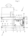
- the device shown in Figures 1 and 3 and each designated 1 is used for accurate angular cutting to length of a hollow profile 2 by means of a hand-operated tool, eg. B. a jigsaw 3, and consists essentially of a clamping device 11 for holding the hollow profile 2 during its processing and a guide member 21 by means of which the saw blade 4 of the jigsaw 3 is guided exactly above and below the hollow profile 2 during the sawing process.
- a running of the saw blade 4 is almost impossible, a clean cutting edge is rather guaranteed by the guidance of the saw blade 4.
- the tensioning device 11 consists of two angularly designed tensioning plates 12 and 13, which thus partially encompass the hollow profile 2 and which can be adjusted relative to one another for the purpose of clamping them.
- guide pins 16 are inserted into two holes 13 machined into the clamping plate 13, which engage holes 15 machined into the clamping plate 12, so that the clamping plate 12 counteracts the force of springs 17 in the direction of the hollow profile, which are also inserted into the graduated holes 15 2 is held adjustable.
- the two clamping plates 12 and 13 are mutually adjustable so that the hollow profile 2 is clamped between them can be and is kept safe during the work process.
- the guide member 21 is formed by two rails 22 and 23 which are arranged parallel to one another and are fixedly connected to the clamping plates 12 and 13 of the clamping device 11 by means of screws 31.
- the rails 22 and 23 each consist of two strips 26 and 27, between which spacers 28 are inserted in the end regions and which are fixed by screws 29 are interconnected. In this way, the rails 22 and 23 can be produced economically. Furthermore, the rails 22 and 23 are each provided with an insertion bevel 30 and, as shown in dash-dotted lines in FIG. 1 in order to avoid damage to the hollow profile 2, can be provided with a coating 23. And in order to be able to support the device 1 in a reliable manner, a support 10 in the form of a plate is fastened by means of screws 32 to the clamping plate 13 of the clamping device 11.
Applications Claiming Priority (2)
| Application Number | Priority Date | Filing Date | Title |
|---|---|---|---|
| DE9217392U | 1992-12-19 | ||
| DE9217392U DE9217392U1 (de) | 1992-12-19 | 1992-12-19 | Vorrichtung zum Ablängen von Hohlprofilen |
Publications (2)
| Publication Number | Publication Date |
|---|---|
| EP0603625A1 true EP0603625A1 (fr) | 1994-06-29 |
| EP0603625B1 EP0603625B1 (fr) | 1999-04-07 |
Family
ID=6887348
Family Applications (1)
| Application Number | Title | Priority Date | Filing Date |
|---|---|---|---|
| EP93119639A Expired - Lifetime EP0603625B1 (fr) | 1992-12-19 | 1993-12-06 | Dispositif pour la coupe en longueur de profilés creux |
Country Status (3)
| Country | Link |
|---|---|
| EP (1) | EP0603625B1 (fr) |
| AT (1) | ATE178518T1 (fr) |
| DE (2) | DE9217392U1 (fr) |
Cited By (2)
| Publication number | Priority date | Publication date | Assignee | Title |
|---|---|---|---|---|
| EP0826453A1 (fr) * | 1996-08-27 | 1998-03-04 | Kambo AG | Equipement pour une scie sauteuse |
| EP2436468A1 (fr) * | 2010-09-29 | 2012-04-04 | Black & Decker Inc. | Scie alternative |
Families Citing this family (4)
| Publication number | Priority date | Publication date | Assignee | Title |
|---|---|---|---|---|
| DE29608100U1 (de) * | 1996-05-07 | 1996-08-08 | Schefe Ines | Vorrichtung zum Ablängen von Hohlprofilen |
| DE102008002076A1 (de) | 2008-05-29 | 2009-12-03 | Hilti Aktiengesellschaft | Haltevorrichtung zum Ablängen eines Hohlprofils |
| DE102011082476A1 (de) * | 2011-09-12 | 2013-03-14 | Hilti Aktiengesellschaft | Handgriff |
| DE102016000180B3 (de) * | 2016-01-11 | 2017-05-11 | Dietmar Schefe | Führungsvorrichtung für Stichsägen |
Citations (4)
| Publication number | Priority date | Publication date | Assignee | Title |
|---|---|---|---|---|
| US2003619A (en) * | 1933-05-10 | 1935-06-04 | Trimont Mfg Co Inc | Pipe cutting device |
| US2111468A (en) * | 1935-11-27 | 1938-03-15 | Leo M Corkum | Hacksaw guide |
| DE1676058U (de) * | 1953-07-30 | 1954-05-13 | Neue Molkereitechnik G M B H | Spann- und fuehrungswerkzeug fuer das absaegen von rohren. |
| FR2579923A1 (en) * | 1985-04-05 | 1986-10-10 | Guiu Claude | Guide slit for apparatus for cutting a bevel in a component |
-
1992
- 1992-12-19 DE DE9217392U patent/DE9217392U1/de not_active Expired - Lifetime
-
1993
- 1993-12-06 DE DE59309500T patent/DE59309500D1/de not_active Expired - Fee Related
- 1993-12-06 EP EP93119639A patent/EP0603625B1/fr not_active Expired - Lifetime
- 1993-12-06 AT AT93119639T patent/ATE178518T1/de not_active IP Right Cessation
Patent Citations (4)
| Publication number | Priority date | Publication date | Assignee | Title |
|---|---|---|---|---|
| US2003619A (en) * | 1933-05-10 | 1935-06-04 | Trimont Mfg Co Inc | Pipe cutting device |
| US2111468A (en) * | 1935-11-27 | 1938-03-15 | Leo M Corkum | Hacksaw guide |
| DE1676058U (de) * | 1953-07-30 | 1954-05-13 | Neue Molkereitechnik G M B H | Spann- und fuehrungswerkzeug fuer das absaegen von rohren. |
| FR2579923A1 (en) * | 1985-04-05 | 1986-10-10 | Guiu Claude | Guide slit for apparatus for cutting a bevel in a component |
Cited By (3)
| Publication number | Priority date | Publication date | Assignee | Title |
|---|---|---|---|---|
| EP0826453A1 (fr) * | 1996-08-27 | 1998-03-04 | Kambo AG | Equipement pour une scie sauteuse |
| EP2436468A1 (fr) * | 2010-09-29 | 2012-04-04 | Black & Decker Inc. | Scie alternative |
| US8776383B2 (en) | 2010-09-29 | 2014-07-15 | Black & Decker Inc. | Clamp for reciprocating saw |
Also Published As
| Publication number | Publication date |
|---|---|
| ATE178518T1 (de) | 1999-04-15 |
| DE9217392U1 (de) | 1994-04-14 |
| EP0603625B1 (fr) | 1999-04-07 |
| DE59309500D1 (de) | 1999-05-12 |
Similar Documents
| Publication | Publication Date | Title |
|---|---|---|
| DE3806116A1 (de) | Vorrichtung zum positionieren von bogenfoermigen kreuzsprossenrahmenteilen und zum fraesen von trapezfoermigen ausnehmungen in diese rahmenteile | |
| DE2702992C2 (de) | Bearbeitungsvorrichtung | |
| EP0603625B1 (fr) | Dispositif pour la coupe en longueur de profilés creux | |
| EP2018922A2 (fr) | Support pour scie circulaire | |
| DE1453213B2 (fr) | ||
| AT409606B (de) | Plattenaufteilsäge | |
| EP0674962B1 (fr) | Dispositif pour la coupe en longueur de profilés creux | |
| EP1679150B1 (fr) | Dispositif pour le perçage des pièces allongées | |
| EP0585423B1 (fr) | Dispositif de serrage sur une machine a couper les tuyaux | |
| EP1800783A1 (fr) | Table de coupe et procédé de coupe de sections de profilés | |
| DE3103722C2 (de) | Anschlagvorrichtung für Holzbearbeitungsmaschinen | |
| EP1563964A1 (fr) | Dispositif auxiliaire pour l'usinage de pièces | |
| EP0807483B1 (fr) | Dispositif pour la coupe en longueur de profilés creux | |
| EP0623420A1 (fr) | Dispositif de transport et de fixation | |
| DE3918710C2 (de) | Gehrungssäge für Glashalteleisten | |
| DE4320622A1 (de) | Vorrichtung zum Ablängen von Hohlprofilen | |
| DE4037614C1 (en) | Powered guiding appts. for machining workpieces - has positioning stop pivoted to protractor adjustable along guide rail | |
| EP0339177A2 (fr) | Dispositif de sciage | |
| DE2059558C3 (de) | Verstellbarer Endanschlag | |
| DE2939769C2 (de) | Führungsvorrichtung für Sägen, insbesondere für Handkreissägen | |
| DE4415904C2 (de) | Vorrichtung zur Führung einer handgeführten Werkzeugmaschine | |
| DE3536830A1 (de) | Oberfraese zur holz- oder kunststoffbearbeitung | |
| DE4224052C2 (de) | Anschlagwinkel für Handarbeitsmaschine | |
| DE7702782U1 (de) | Säge für Steinwerkstücke | |
| DE2025374A1 (de) | Vorrichtung zum stationären Betrieb von in eine motorisch angetriebene Hand bohrmaschine eingesetzten, umlaufenden Werkzeugen |
Legal Events
| Date | Code | Title | Description |
|---|---|---|---|
| PUAI | Public reference made under article 153(3) epc to a published international application that has entered the european phase |
Free format text: ORIGINAL CODE: 0009012 |
|
| AK | Designated contracting states |
Kind code of ref document: A1 Designated state(s): AT CH DE ES FR GB IT LI SE |
|
| 17P | Request for examination filed |
Effective date: 19941214 |
|
| 17Q | First examination report despatched |
Effective date: 19970120 |
|
| GRAG | Despatch of communication of intention to grant |
Free format text: ORIGINAL CODE: EPIDOS AGRA |
|
| GRAG | Despatch of communication of intention to grant |
Free format text: ORIGINAL CODE: EPIDOS AGRA |
|
| GRAH | Despatch of communication of intention to grant a patent |
Free format text: ORIGINAL CODE: EPIDOS IGRA |
|
| GRAH | Despatch of communication of intention to grant a patent |
Free format text: ORIGINAL CODE: EPIDOS IGRA |
|
| GRAA | (expected) grant |
Free format text: ORIGINAL CODE: 0009210 |
|
| AK | Designated contracting states |
Kind code of ref document: B1 Designated state(s): AT CH DE ES FR GB IT LI SE |
|
| PG25 | Lapsed in a contracting state [announced via postgrant information from national office to epo] |
Ref country code: SE Free format text: THE PATENT HAS BEEN ANNULLED BY A DECISION OF A NATIONAL AUTHORITY Effective date: 19990407 Ref country code: IT Free format text: LAPSE BECAUSE OF FAILURE TO SUBMIT A TRANSLATION OF THE DESCRIPTION OR TO PAY THE FEE WITHIN THE PRE;WARNING: LAPSES OF ITALIAN PATENTS WITH EFFECTIVE DATE BEFORE 2007 MAY HAVE OCCURRED AT ANY TIME BEFORE 2007. THE CORRECT EFFECTIVE DATE MAY BE DIFFERENT FROM THE ONE RECORDED.SCRIBED TIME-LIMIT Effective date: 19990407 Ref country code: GB Free format text: LAPSE BECAUSE OF NON-PAYMENT OF DUE FEES Effective date: 19990407 Ref country code: FR Free format text: LAPSE BECAUSE OF FAILURE TO SUBMIT A TRANSLATION OF THE DESCRIPTION OR TO PAY THE FEE WITHIN THE PRESCRIBED TIME-LIMIT Effective date: 19990407 Ref country code: ES Free format text: THE PATENT HAS BEEN ANNULLED BY A DECISION OF A NATIONAL AUTHORITY Effective date: 19990407 |
|
| REF | Corresponds to: |
Ref document number: 178518 Country of ref document: AT Date of ref document: 19990415 Kind code of ref document: T |
|
| REG | Reference to a national code |
Ref country code: CH Ref legal event code: EP |
|
| REF | Corresponds to: |
Ref document number: 59309500 Country of ref document: DE Date of ref document: 19990512 |
|
| EN | Fr: translation not filed | ||
| GBV | Gb: ep patent (uk) treated as always having been void in accordance with gb section 77(7)/1977 [no translation filed] |
Effective date: 19990407 |
|
| PG25 | Lapsed in a contracting state [announced via postgrant information from national office to epo] |
Ref country code: AT Free format text: LAPSE BECAUSE OF NON-PAYMENT OF DUE FEES Effective date: 19991206 |
|
| PG25 | Lapsed in a contracting state [announced via postgrant information from national office to epo] |
Ref country code: LI Free format text: LAPSE BECAUSE OF NON-PAYMENT OF DUE FEES Effective date: 19991231 Ref country code: CH Free format text: LAPSE BECAUSE OF NON-PAYMENT OF DUE FEES Effective date: 19991231 |
|
| PLBE | No opposition filed within time limit |
Free format text: ORIGINAL CODE: 0009261 |
|
| STAA | Information on the status of an ep patent application or granted ep patent |
Free format text: STATUS: NO OPPOSITION FILED WITHIN TIME LIMIT |
|
| 26N | No opposition filed | ||
| PGFP | Annual fee paid to national office [announced via postgrant information from national office to epo] |
Ref country code: DE Payment date: 20010216 Year of fee payment: 8 |
|
| PG25 | Lapsed in a contracting state [announced via postgrant information from national office to epo] |
Ref country code: DE Free format text: LAPSE BECAUSE OF NON-PAYMENT OF DUE FEES Effective date: 20020702 |