EP2018922A2 - Support pour scie circulaire - Google Patents
Support pour scie circulaire Download PDFInfo
- Publication number
- EP2018922A2 EP2018922A2 EP20080104132 EP08104132A EP2018922A2 EP 2018922 A2 EP2018922 A2 EP 2018922A2 EP 20080104132 EP20080104132 EP 20080104132 EP 08104132 A EP08104132 A EP 08104132A EP 2018922 A2 EP2018922 A2 EP 2018922A2
- Authority
- EP
- European Patent Office
- Prior art keywords
- circular saw
- clamping
- clamping element
- saw stand
- stand according
- Prior art date
- Legal status (The legal status is an assumption and is not a legal conclusion. Google has not performed a legal analysis and makes no representation as to the accuracy of the status listed.)
- Withdrawn
Links
- 238000005520 cutting process Methods 0.000 description 4
- 238000010276 construction Methods 0.000 description 2
- 230000006978 adaptation Effects 0.000 description 1
- 238000004519 manufacturing process Methods 0.000 description 1
Images
Classifications
-
- B—PERFORMING OPERATIONS; TRANSPORTING
- B23—MACHINE TOOLS; METAL-WORKING NOT OTHERWISE PROVIDED FOR
- B23D—PLANING; SLOTTING; SHEARING; BROACHING; SAWING; FILING; SCRAPING; LIKE OPERATIONS FOR WORKING METAL BY REMOVING MATERIAL, NOT OTHERWISE PROVIDED FOR
- B23D47/00—Sawing machines or sawing devices working with circular saw blades, characterised only by constructional features of particular parts
- B23D47/02—Sawing machines or sawing devices working with circular saw blades, characterised only by constructional features of particular parts of frames; of guiding arrangements for work-table or saw-carrier
-
- B—PERFORMING OPERATIONS; TRANSPORTING
- B23—MACHINE TOOLS; METAL-WORKING NOT OTHERWISE PROVIDED FOR
- B23D—PLANING; SLOTTING; SHEARING; BROACHING; SAWING; FILING; SCRAPING; LIKE OPERATIONS FOR WORKING METAL BY REMOVING MATERIAL, NOT OTHERWISE PROVIDED FOR
- B23D47/00—Sawing machines or sawing devices working with circular saw blades, characterised only by constructional features of particular parts
- B23D47/04—Sawing machines or sawing devices working with circular saw blades, characterised only by constructional features of particular parts of devices for feeding, positioning, clamping, or rotating work
-
- B—PERFORMING OPERATIONS; TRANSPORTING
- B23—MACHINE TOOLS; METAL-WORKING NOT OTHERWISE PROVIDED FOR
- B23D—PLANING; SLOTTING; SHEARING; BROACHING; SAWING; FILING; SCRAPING; LIKE OPERATIONS FOR WORKING METAL BY REMOVING MATERIAL, NOT OTHERWISE PROVIDED FOR
- B23D59/00—Accessories specially designed for sawing machines or sawing devices
- B23D59/007—Accessories specially designed for sawing machines or sawing devices for mounting a portable sawing device on a frame part
-
- B—PERFORMING OPERATIONS; TRANSPORTING
- B25—HAND TOOLS; PORTABLE POWER-DRIVEN TOOLS; MANIPULATORS
- B25H—WORKSHOP EQUIPMENT, e.g. FOR MARKING-OUT WORK; STORAGE MEANS FOR WORKSHOPS
- B25H1/00—Work benches; Portable stands or supports for positioning portable tools or work to be operated on thereby
- B25H1/0021—Stands, supports or guiding devices for positioning portable tools or for securing them to the work
- B25H1/0078—Guiding devices for hand tools
-
- Y—GENERAL TAGGING OF NEW TECHNOLOGICAL DEVELOPMENTS; GENERAL TAGGING OF CROSS-SECTIONAL TECHNOLOGIES SPANNING OVER SEVERAL SECTIONS OF THE IPC; TECHNICAL SUBJECTS COVERED BY FORMER USPC CROSS-REFERENCE ART COLLECTIONS [XRACs] AND DIGESTS
- Y10—TECHNICAL SUBJECTS COVERED BY FORMER USPC
- Y10T—TECHNICAL SUBJECTS COVERED BY FORMER US CLASSIFICATION
- Y10T83/00—Cutting
- Y10T83/748—With work immobilizer
- Y10T83/7487—Means to clamp work
-
- Y—GENERAL TAGGING OF NEW TECHNOLOGICAL DEVELOPMENTS; GENERAL TAGGING OF CROSS-SECTIONAL TECHNOLOGIES SPANNING OVER SEVERAL SECTIONS OF THE IPC; TECHNICAL SUBJECTS COVERED BY FORMER USPC CROSS-REFERENCE ART COLLECTIONS [XRACs] AND DIGESTS
- Y10—TECHNICAL SUBJECTS COVERED BY FORMER USPC
- Y10T—TECHNICAL SUBJECTS COVERED BY FORMER US CLASSIFICATION
- Y10T83/00—Cutting
- Y10T83/768—Rotatable disc tool pair or tool and carrier
- Y10T83/7684—With means to support work relative to tool[s]
Definitions
- the invention relates to a circular saw stand for the production of cuts by means of a hand-held circular saw with the features according to the preamble of claim 1.
- the circular saw stand a fixing device for its attachment to a countertop, a receiving area for receiving a workpiece to be machined, and a guide device on, which forms a management level for a contact plate of the circular saw.
- the workpiece to be machined is arranged and fixed in a desired position in the receiving area. Subsequently, a cut along the guide device can be performed with a commercial circular saw, wherein the abutment plate is placed on the guide level and moved along the same. This makes a particularly accurate cut possible.
- a device for guiding a hand-held saw is known. This has two parallel guide rails, on each of which rests an edge region of a contact plate of the saw.
- the guide rails are held at their ends via a locking device formed by console elements on a workbench, wherein the console elements each have height-adjustable screw with the workbench.
- a disadvantage of the known device is that it can only be adjusted by loosening and re-tightening all four screw to different heights of the workpiece to be machined. Furthermore, in this device for fixing the workpiece is essentially a flat top of the worktable, which in particular the processing of workpieces with round cross-sections, such as pipes, difficult or additional means for secure determination requires, however, in turn increase the operating effort.
- the present invention has for its object to avoid the disadvantages mentioned in a circular saw stand and to increase a comfortable and quick adjustment to different sized workpieces and to ensure a secure fixing, especially of workpieces with a round cross-section.
- a circular saw stand with the features of claim 1, wherein the receiving area is adjustably limited by a clamping device having a firmly connected to the fixing device fixed clamping element and a relative to the fixed clamping element displaceable clamping element, wherein the guide means at one of Clamping elements is mounted.
- the displaceable clamping element is adjustable over a single handle relative to the fixed clamping element, which allows a particularly comfortable and quick adjustment of the circular saw stand for adaptation to differently sized workpieces.
- the guide plane is formed by a single guide plate of the guide means, whereby a compact construction allows and precise guidance can be ensured.
- the displaceable clamping element is formed by a clamping loop and the fixed clamping element by a stop side of a frame which carries the guide device.
- the single handle is formed by a rotatable threaded member and the clamping loop clamped by means of a tension member which is linearly displaceable over the threaded member.
- the tensioning loop is particularly easy adjustable between a clamping position and a release position.
- the fixed clamping element is provided by a first clamping jaw and the movable clamping element by a relative to the first Clamping jaw displaceable second clamping jaw formed, which is arranged on a support which carries the guide device.
- clamping jaws each have two mutually oppositely inclined clamping surfaces, which in addition also workpieces can be securely clamped with a substantially circular cross-section.
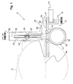
- Fig. 1 shows a circular saw stand 2 for making cuts by means of a hand-held circular saw 4.
- the circular saw stand 2 a fixing device 6 in the form of a screw, by means of a frame 8 of the circular saw stand 2 on a worktop 10, which may be part of a workbench, for example can be.
- the circular saw stand 2 has a clamping device 12, which defines a receiving region 14, in which a workpiece 16, for example in the form of a tube can be fixed.
- the clamping device 12 has a fixed clamping element acting as a stop side 18 of the frame 8 and acting as a displaceable clamping element tensioning loop 20.
- the tensioning loop 20 may be formed, for example, by a rope, band or chain-like element, which may also have a certain elasticity depending on the intended area of use.
- a tension member 22 in the form of a sliding block translationally displaceable, which surrounds the clamping loop 20 with the interposition of a deflecting element 24.
- the sliding block is slidably but non-rotatably guided in a groove 26 and has a threaded bore 28 which cooperates with a threaded rod 30 which is rotatable from the outside by means of a handle 32 designed as a handle.
- the tension member 22 is displaced in one or the other direction, wherein the receiving portion 14 is widened or reduced and thus the clamping device 12 in a clamping position for fixing the workpiece to be machined 16 or in a release position can be transferred, in the example previously machined workpiece 16 can be removed again from the clamping device 12.
- a guide plate 34 perpendicular from an end face 36 thereof from the top 38 forms a closed guide plane for a contact plate 40 of the circular saw 4.
- the guide plate 34 forms together with the end face 36 of the frame 8, a guide device 42 along which the circular saw 2 can be safely guided during the cutting process.
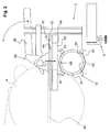
- Fig. 2 shows a further embodiment of the circular saw stand 2, wherein elements with corresponding function have the same reference numerals as in Fig. 1 ,
- the clamping device 12 has a first clamping jaw 50, which acts as a fixed clamping element, and a second clamping jaw 52, which acts as a displaceable clamping element.
- the first jaw 50 is fixedly connected to the fixing device 6 while the second jaw 52 is provided on a carrier 54, the means of acting as a handle pivotable clamping lever 56 actuatable quick release device 58 in the clamping position and release position of the clamping device 12 back and forth is.
- the guide device 42 is formed in this case by an end face 60 of the carrier 54 and a surface 62 of a guide plate 64, which in turn protrudes perpendicularly from the end face 60.
- the two jaws 50, 52 each have two mutually oppositely inclined clamping surfaces 66, whereby each recess 68 is formed the workpiece 16 can be securely fixed.
- two tension rollers 67 are provided on the two clamping jaws 50, 52 on the outer edges, whereby pipes of larger diameter (greater than the cutting depth of the circular saw blade) rotatably braced and thus can be cut through circumferentially.
- the application plate 40 of the circular saw 4 is now applied to the guide plate 64 and displaced on this, while the end face 60 provides lateral guidance.
Landscapes
- Engineering & Computer Science (AREA)
- Mechanical Engineering (AREA)
- Sawing (AREA)
Applications Claiming Priority (1)
| Application Number | Priority Date | Filing Date | Title |
|---|---|---|---|
| DE200710000409 DE102007000409A1 (de) | 2007-07-27 | 2007-07-27 | Kreissägenständer |
Publications (2)
| Publication Number | Publication Date |
|---|---|
| EP2018922A2 true EP2018922A2 (fr) | 2009-01-28 |
| EP2018922A3 EP2018922A3 (fr) | 2011-10-12 |
Family
ID=39884100
Family Applications (1)
| Application Number | Title | Priority Date | Filing Date |
|---|---|---|---|
| EP20080104132 Withdrawn EP2018922A3 (fr) | 2007-07-27 | 2008-05-28 | Support pour scie circulaire |
Country Status (3)
| Country | Link |
|---|---|
| US (1) | US20090025520A1 (fr) |
| EP (1) | EP2018922A3 (fr) |
| DE (1) | DE102007000409A1 (fr) |
Cited By (3)
| Publication number | Priority date | Publication date | Assignee | Title |
|---|---|---|---|---|
| CN103331482A (zh) * | 2013-07-08 | 2013-10-02 | 嵊州市龙威机械制造有限公司 | 一种电动切割机 |
| CN114245770A (zh) * | 2019-08-16 | 2022-03-25 | 潘泰克Gs系统有限公司 | 用于平面压印机的工具板定位的设备 |
| CN117103363A (zh) * | 2023-10-16 | 2023-11-24 | 四川英创力电子科技股份有限公司 | 用于电路板钻孔的夹持组件及其使用方法 |
Families Citing this family (4)
| Publication number | Priority date | Publication date | Assignee | Title |
|---|---|---|---|---|
| US8549760B2 (en) * | 2008-07-25 | 2013-10-08 | Milwaukee Electric Tool Corporation | Adjustable locking shoe |
| US8549759B2 (en) * | 2008-07-25 | 2013-10-08 | Milwaukee Electric Tool Corporation | Adjustable shoe for a power tool |
| DE102011089555A1 (de) | 2011-12-22 | 2013-06-27 | Hilti Aktiengesellschaft | Spann- und Führungseinrichtung für ein handgeführtes Werkzeuggerät |
| US12070809B2 (en) | 2019-03-01 | 2024-08-27 | Milwaukee Electric Tool Corporation | Band saw |
Citations (1)
| Publication number | Priority date | Publication date | Assignee | Title |
|---|---|---|---|---|
| WO2003041907A1 (fr) | 2001-11-10 | 2003-05-22 | Anton Kessel Gmbh & Co. Kg. | Dispositif de guidage pour scies |
Family Cites Families (9)
| Publication number | Priority date | Publication date | Assignee | Title |
|---|---|---|---|---|
| US947928A (en) * | 1908-12-22 | 1910-02-01 | Robert J Mcghee | Drag-saw machine. |
| US3449992A (en) * | 1967-03-02 | 1969-06-17 | Charles D Hanaway | Manually-held power-driven pipe cutter |
| US3807268A (en) * | 1972-07-28 | 1974-04-30 | C Bacon | Portable tube cutting hand saw and attachment |
| DE8900045U1 (de) * | 1988-01-21 | 1989-03-09 | Werkzeug GmbH, 56745 Weibern | Werktisch |
| WO1997029880A1 (fr) * | 1996-02-13 | 1997-08-21 | Robert Maurice Renn | Outil multi-usage pour operations miniaturisees |
| US6553669B2 (en) * | 1997-07-07 | 2003-04-29 | Sam W. Carter | Pipe cutter and method of cutting pipe |
| DE29922829U1 (de) * | 1999-12-24 | 2000-03-30 | Chen, Tony, Taipeh/T'ai-pei | Schnellspannvorrichtung für eine Metallschneidemaschine |
| CA2494789A1 (fr) * | 2005-01-17 | 2006-07-17 | Larry W. Macdonald | Reglette de guidage de scie electrique portative pour etablis pliants |
| FR2888143B1 (fr) * | 2005-07-07 | 2008-08-08 | Andre Dieu | Guide d'usinage |
-
2007
- 2007-07-27 DE DE200710000409 patent/DE102007000409A1/de not_active Withdrawn
-
2008
- 2008-05-28 EP EP20080104132 patent/EP2018922A3/fr not_active Withdrawn
- 2008-07-24 US US12/220,641 patent/US20090025520A1/en not_active Abandoned
Patent Citations (1)
| Publication number | Priority date | Publication date | Assignee | Title |
|---|---|---|---|---|
| WO2003041907A1 (fr) | 2001-11-10 | 2003-05-22 | Anton Kessel Gmbh & Co. Kg. | Dispositif de guidage pour scies |
Cited By (5)
| Publication number | Priority date | Publication date | Assignee | Title |
|---|---|---|---|---|
| CN103331482A (zh) * | 2013-07-08 | 2013-10-02 | 嵊州市龙威机械制造有限公司 | 一种电动切割机 |
| CN114245770A (zh) * | 2019-08-16 | 2022-03-25 | 潘泰克Gs系统有限公司 | 用于平面压印机的工具板定位的设备 |
| CN114245770B (zh) * | 2019-08-16 | 2024-06-07 | 潘泰克Gs系统有限公司 | 用于平面压印机的工具板定位的设备 |
| CN117103363A (zh) * | 2023-10-16 | 2023-11-24 | 四川英创力电子科技股份有限公司 | 用于电路板钻孔的夹持组件及其使用方法 |
| CN117103363B (zh) * | 2023-10-16 | 2024-04-02 | 四川英创力电子科技股份有限公司 | 用于电路板钻孔的夹持组件及其使用方法 |
Also Published As
| Publication number | Publication date |
|---|---|
| EP2018922A3 (fr) | 2011-10-12 |
| DE102007000409A1 (de) | 2009-01-29 |
| US20090025520A1 (en) | 2009-01-29 |
Similar Documents
| Publication | Publication Date | Title |
|---|---|---|
| EP2018922A2 (fr) | Support pour scie circulaire | |
| EP0682589B1 (fr) | Poignee interchangeable pour cales coulissantes | |
| DE202013103810U1 (de) | Zentrischspanner | |
| EP2412490B1 (fr) | Système de fixation | |
| EP2849907B1 (fr) | Dispositif de fixation d'une pièce à usiner au moyen d'une machine d'usinage | |
| EP1466688B1 (fr) | Scie circulaire | |
| EP2891549A2 (fr) | Outil à lame ronde | |
| DE3606795A1 (de) | Vorrichtung zum verstellen eines werkstueckanschlags oder dergleichen fuer eine holzbearbeitungsmaschine | |
| EP3702100B1 (fr) | Dispositif de butée | |
| EP2974839B1 (fr) | Machine de coupe manuelle ayant deux paliers de guidage à onglet | |
| DE2447243A1 (de) | Niederzug-werkstueckspannvorrichtung, insbesondere niederzug-maschinenschraubstock | |
| DE4037614C1 (en) | Powered guiding appts. for machining workpieces - has positioning stop pivoted to protractor adjustable along guide rail | |
| EP1563964A1 (fr) | Dispositif auxiliaire pour l'usinage de pièces | |
| DE202004009517U1 (de) | Spanneinrichtung | |
| EP3318375B1 (fr) | Machine-outil dotée du dispositif d'élingage réglable | |
| EP1236537B1 (fr) | Procédé pour le réglage d'au moins un élément de pression d'une machine à travailler des pièces à usiner en bois, plastique ou similaires, dispositif de réglage pour la mise en oeuvre d'un tel procédé et élément de pression pour un tel procédé | |
| EP0603625A1 (fr) | Dispositif pour la coupe en longueur de profilés creux | |
| DE4415904C2 (de) | Vorrichtung zur Führung einer handgeführten Werkzeugmaschine | |
| DE10252022B4 (de) | Rohrabschneider | |
| DE102010039108A1 (de) | Handwerkzeugmaschine, insbesondere Säge, wie Kreissäge, Stichsäge od. dgl. | |
| AT518770B1 (de) | Werkzeug zum Bearbeiten einer Nut | |
| CH307069A (de) | Schraubstock, insbesondere für Fräsmaschinen und Drehbänke. | |
| EP2527070A1 (fr) | Scie circulaire de format avec dispositif de guidage | |
| DE102022111672A1 (de) | Spannvorrichtung für eine Kreissäge | |
| DE1002519C2 (de) | Einrichtung zur einstellung und führung von werkstücken an maschinenbandsägen, fräsmaschinen u. dgl. |
Legal Events
| Date | Code | Title | Description |
|---|---|---|---|
| PUAI | Public reference made under article 153(3) epc to a published international application that has entered the european phase |
Free format text: ORIGINAL CODE: 0009012 |
|
| AK | Designated contracting states |
Kind code of ref document: A2 Designated state(s): AT BE BG CH CY CZ DE DK EE ES FI FR GB GR HR HU IE IS IT LI LT LU LV MC MT NL NO PL PT RO SE SI SK TR |
|
| AX | Request for extension of the european patent |
Extension state: AL BA MK RS |
|
| PUAL | Search report despatched |
Free format text: ORIGINAL CODE: 0009013 |
|
| RIC1 | Information provided on ipc code assigned before grant |
Ipc: B25H 1/00 20060101ALI20110901BHEP Ipc: B23D 59/00 20060101ALI20110901BHEP Ipc: B23D 47/04 20060101ALI20110901BHEP Ipc: B23D 47/02 20060101AFI20110901BHEP |
|
| AK | Designated contracting states |
Kind code of ref document: A3 Designated state(s): AT BE BG CH CY CZ DE DK EE ES FI FR GB GR HR HU IE IS IT LI LT LU LV MC MT NL NO PL PT RO SE SI SK TR |
|
| AX | Request for extension of the european patent |
Extension state: AL BA MK RS |
|
| 17P | Request for examination filed |
Effective date: 20111116 |
|
| AKX | Designation fees paid |
Designated state(s): AT BE BG CH CY CZ DE DK EE ES FI FR GB GR HR HU IE IS IT LI LT LU LV MC MT NL NO PL PT RO SE SI SK TR |
|
| STAA | Information on the status of an ep patent application or granted ep patent |
Free format text: STATUS: THE APPLICATION IS DEEMED TO BE WITHDRAWN |
|
| 18D | Application deemed to be withdrawn |
Effective date: 20120413 |