EP0603625A1 - Device for cutting at length hollow structural members - Google Patents
Device for cutting at length hollow structural members Download PDFInfo
- Publication number
- EP0603625A1 EP0603625A1 EP93119639A EP93119639A EP0603625A1 EP 0603625 A1 EP0603625 A1 EP 0603625A1 EP 93119639 A EP93119639 A EP 93119639A EP 93119639 A EP93119639 A EP 93119639A EP 0603625 A1 EP0603625 A1 EP 0603625A1
- Authority
- EP
- European Patent Office
- Prior art keywords
- clamping
- clamping plates
- hollow profile
- guide member
- cut
- Prior art date
- Legal status (The legal status is an assumption and is not a legal conclusion. Google has not performed a legal analysis and makes no representation as to the accuracy of the status listed.)
- Granted
Links
Images


Classifications
-
- B—PERFORMING OPERATIONS; TRANSPORTING
- B23—MACHINE TOOLS; METAL-WORKING NOT OTHERWISE PROVIDED FOR
- B23Q—DETAILS, COMPONENTS, OR ACCESSORIES FOR MACHINE TOOLS, e.g. ARRANGEMENTS FOR COPYING OR CONTROLLING; MACHINE TOOLS IN GENERAL CHARACTERISED BY THE CONSTRUCTION OF PARTICULAR DETAILS OR COMPONENTS; COMBINATIONS OR ASSOCIATIONS OF METAL-WORKING MACHINES, NOT DIRECTED TO A PARTICULAR RESULT
- B23Q9/00—Arrangements for supporting or guiding portable metal-working machines or apparatus
- B23Q9/0064—Portable machines cooperating with guide means not supported by the workpiece during working
- B23Q9/0078—Portable machines cooperating with guide means not supported by the workpiece during working the guide means being fixed to a support
-
- B—PERFORMING OPERATIONS; TRANSPORTING
- B23—MACHINE TOOLS; METAL-WORKING NOT OTHERWISE PROVIDED FOR
- B23D—PLANING; SLOTTING; SHEARING; BROACHING; SAWING; FILING; SCRAPING; LIKE OPERATIONS FOR WORKING METAL BY REMOVING MATERIAL, NOT OTHERWISE PROVIDED FOR
- B23D49/00—Machines or devices for sawing with straight reciprocating saw blades, e.g. hacksaws
- B23D49/002—Machines or devices for sawing with straight reciprocating saw blades, e.g. hacksaws with means to attach the sawing device to the work
-
- B—PERFORMING OPERATIONS; TRANSPORTING
- B23—MACHINE TOOLS; METAL-WORKING NOT OTHERWISE PROVIDED FOR
- B23D—PLANING; SLOTTING; SHEARING; BROACHING; SAWING; FILING; SCRAPING; LIKE OPERATIONS FOR WORKING METAL BY REMOVING MATERIAL, NOT OTHERWISE PROVIDED FOR
- B23D51/00—Sawing machines or sawing devices working with straight blades, characterised only by constructional features of particular parts; Carrying or attaching means for tools, covered by this subclass, which are connected to a carrier at both ends
- B23D51/02—Sawing machines or sawing devices working with straight blades, characterised only by constructional features of particular parts; Carrying or attaching means for tools, covered by this subclass, which are connected to a carrier at both ends of beds; of guiding arrangements for work-tables or saw carriers; of frames
- B23D51/025—Sawing machines or sawing devices working with straight blades, characterised only by constructional features of particular parts; Carrying or attaching means for tools, covered by this subclass, which are connected to a carrier at both ends of beds; of guiding arrangements for work-tables or saw carriers; of frames of arrangements for guiding the saw blade
Definitions
- the invention relates to a device for cutting hollow profiles, in particular channel profiles made of sheet steel for parapet channels, by means of a jigsaw or a similar tool to be guided by hand.
- Parapet ducts made of hollow profiles are being used more and more for covered laying of electrical supply lines.
- Such hollow profiles made of plastic or aluminum, which are supplied in long lengths, can be easily sawed off at the respective construction site with a hand-held circular saw without difficulty and in a short time to the required extent, but these profiles are relatively expensive, so that for cost reasons often the installation of hollow sections made of sheet steel is desired.
- the object of the invention is therefore to provide a device for cutting hollow sections to length, by means of which it is possible in a very simple manner and in a short time to cut a hollow section consisting of sheet steel with a hand-held tool, for example a jigsaw, to a precise dimension without that a running of the tool has to be accepted. Rather, it should be achieved that the tool is reliably guided during the cutting process and that all walls of the hollow profile can be cut in one operation.
- the construction effort required for this should be kept low, so that economical production is also possible, and the device should also be able to be easily taken to a construction site and only be operated by one person, and should therefore always be ready for use with simple handling.
- the device for cutting to length of hollow profiles is characterized by a tensioning device for holding the hollow profile and a guide member connected thereto, which can be placed on the hollow profile to be cut, and which extends on two opposite sides in a common plane Has guide slots for receiving the saw blade of the jigsaw.
- the clamping device should expediently consist of two mutually adjustable, preferably angled clamping plates, between which the hollow profile to be cut can be clamped, the clamping plates being adjustably connected to one another by guide bolts or the like inserted therein and preferably by means of one or more clamping screws against the force of the Guide bolts held by compression springs can be clamped.
- the guide member by means of two rails which are attached to the clamping plates, preferably axially perpendicular to the hollow profile to be cut and which are of an angular shape and into which the slots arranged in a common plane for receiving the saw blade are incorporated.
- the rails can each consist of two strips arranged at a lateral distance from one another, between which spacers are inserted in the two end regions.
- the guide member by a U-shaped or closed frame, in each of which a slot for receiving the saw blade is machined in the legs arranged in the plane of the clamping plates.
- a device for cutting hollow profiles according to the invention in which a tensioning device acting on it is provided with a guide member which has two mutually opposite guide slots running in one plane, it is easily possible during a sawing operation to saw one of the saw blades Hand-adjustable jigsaw to guide exactly, so that a flawless uniform cutting edge can be achieved.
- a running of the saw blade is almost impossible by guiding it on two sides of the hollow profile, faulty machining even of hollow profiles made of sheet steel are therefore not to be accepted. Rather, these can be cut to size and angularly by almost anyone on a construction site without difficulty.
- the proposed device consists of only a few simply designed components, it can also be produced economically and does not build large, so it is easily possible to take it to construction sites.
- the device according to the application for cutting hollow profiles to length makes it possible, with simple handling, to preform steel sheet hollow profiles To edit place without much effort, so that parapet channels can be produced inexpensively from such hollow profiles.
- the device shown in Figures 1 and 3 and each designated 1 is used for accurate angular cutting to length of a hollow profile 2 by means of a hand-operated tool, eg. B. a jigsaw 3, and consists essentially of a clamping device 11 for holding the hollow profile 2 during its processing and a guide member 21 by means of which the saw blade 4 of the jigsaw 3 is guided exactly above and below the hollow profile 2 during the sawing process.
- a running of the saw blade 4 is almost impossible, a clean cutting edge is rather guaranteed by the guidance of the saw blade 4.
- the tensioning device 11 consists of two angularly designed tensioning plates 12 and 13, which thus partially encompass the hollow profile 2 and which can be adjusted relative to one another for the purpose of clamping them.
- guide pins 16 are inserted into two holes 13 machined into the clamping plate 13, which engage holes 15 machined into the clamping plate 12, so that the clamping plate 12 counteracts the force of springs 17 in the direction of the hollow profile, which are also inserted into the graduated holes 15 2 is held adjustable.
- the two clamping plates 12 and 13 are mutually adjustable so that the hollow profile 2 is clamped between them can be and is kept safe during the work process.
- the guide member 21 is formed by two rails 22 and 23 which are arranged parallel to one another and are fixedly connected to the clamping plates 12 and 13 of the clamping device 11 by means of screws 31.
- the rails 22 and 23 each consist of two strips 26 and 27, between which spacers 28 are inserted in the end regions and which are fixed by screws 29 are interconnected. In this way, the rails 22 and 23 can be produced economically. Furthermore, the rails 22 and 23 are each provided with an insertion bevel 30 and, as shown in dash-dotted lines in FIG. 1 in order to avoid damage to the hollow profile 2, can be provided with a coating 23. And in order to be able to support the device 1 in a reliable manner, a support 10 in the form of a plate is fastened by means of screws 32 to the clamping plate 13 of the clamping device 11.
Abstract
Description
Die Erfindung bezieht sich auf eine Vorrichtung zum Ablängen von Hohlprofilen, insbesondere von Kanalprofilen aus Stahlblech für Brüstungskanäle, mittels einer von Hand zu führenden Stichsäge oder eines ähnlichen Werkzeuges.The invention relates to a device for cutting hollow profiles, in particular channel profiles made of sheet steel for parapet channels, by means of a jigsaw or a similar tool to be guided by hand.
Zur abgedeckten Verlegung von elektrischen Versorgungsleitungen werden mehr und mehr aus Hohlprofilen hergestellte Brüstungskanäle verwendet. Derartige aus Kunststoff oder Aluminium bestehende Hohlprofile, die in großen Längen angeliefert werden, können zwar ohne weiteres auf der jeweiligen Baustelle mit einer Handkreissäge ohne Schwierigkeiten und in kurzer Zeit auf das erforderliche Maß abgesägt werden, diese Profile sind aber verhältnismäßig teuer, so daß aus Kostengründen oftmals der Einbau von aus Stahlblech gefertigten Hohlprofilen gewünscht wird.Parapet ducts made of hollow profiles are being used more and more for covered laying of electrical supply lines. Such hollow profiles made of plastic or aluminum, which are supplied in long lengths, can be easily sawed off at the respective construction site with a hand-held circular saw without difficulty and in a short time to the required extent, but these profiles are relatively expensive, so that for cost reasons often the installation of hollow sections made of sheet steel is desired.
Zum Ablängen von Hohlprofilen aus Stahlblech ist aber, um eine exakte Schnittkante zu erhalten, eine mit einem feinzahnigen Sägeblatt bestückte Bandsäge notwendig, die meist stationär in einer Werkstatt aufgestellt ist und nicht ohne weiteres auf eine Baustelle verbracht werden kann. Die für Brüstungskanäle vorgesehenen Hohlprofile sind demnach in eine räumlich entfernte Werkstatt zu bringen und dort mit Hilfe der Bandkreissäge auf Maß abzusägen. Dies ist nicht nur sehr zeitaufwendig und damit lohnintensiv, sondern dabei treten vielfach auch Bearbeitungsfehler auf, so daß auf der Baustelle zusätzliche Nacharbeiten unumgänglich sind. Und beim Ablängen eines aus Stahlblech gefertigten Hohlprofiles von Hand, in dem z. B. mittels einer Stichsäge die einzelnen Wände des Profils nacheinander abgesägt werden, ist eine an allen Wänden gleich verlaufende Schnittkante nicht oder nur mit einem außerordentlich großen Geschick zu bewerkstelligen. Hohlprofile aus Stahlblech werden daher aufgrund der bei deren Bearbeitung auftretenden Schwierigkeiten nur selten verwendet.To cut hollow sections made of sheet steel, a band saw equipped with a fine-toothed saw blade, which is usually installed stationary in a workshop, is necessary to obtain an exact cutting edge and cannot be easily taken to a construction site. The hollow profiles intended for parapet ducts must therefore be brought to a remote workshop and sawed to size using the circular saw. This is not only very time-consuming and therefore wage-intensive, but also processing errors often occur, so that additional reworking is unavoidable on the construction site. And when cutting a hollow section made of sheet steel by hand, in which, for. B. the individual walls of the profile are sawn off one after the other by means of a jigsaw, a cutting edge that is the same on all walls cannot be accomplished or can only be accomplished with an extremely high degree of skill. Hollow sections made of sheet steel are therefore only rarely used due to the difficulties encountered in processing them.
Aufgabe der Erfindung ist es demnach, eine Vorrichtung zum Ablängen von Hohlprofilen zu schaffen, mittels der es auf sehr einfache Weise und in kurzer Zeit möglich ist, ein aus Stahlblech bestehendes Hohlprofil mit einem Handarbeitsgerät, beispielsweise einer Stichsäge, auf einer Baustelle maßgenau abzulängen, ohne daß dabei ein Verlaufen des Werkzeuges in Kauf zu nehmen ist. Vielmehr soll erreicht werden, daß das Werkzeug während des Schneidvorganges zuverlässig geführt ist und daß in einem Arbeitsgang alle Wände des Hohlprofils durchtrennt werden können. Der dazu erforderliche Bauaufwand soll gering gehalten werden, so daß auch eine wirtschaftliche Fertigung möglich ist, auch soll die Vorrichtung problemlos auf eine Baustelle mitzunehmen und nur von einer Person bedient werden können, eine ständige Einsatzbereitschaft soll demnach bei einfacher Handhabung stets gegeben sein.The object of the invention is therefore to provide a device for cutting hollow sections to length, by means of which it is possible in a very simple manner and in a short time to cut a hollow section consisting of sheet steel with a hand-held tool, for example a jigsaw, to a precise dimension without that a running of the tool has to be accepted. Rather, it should be achieved that the tool is reliably guided during the cutting process and that all walls of the hollow profile can be cut in one operation. The construction effort required for this should be kept low, so that economical production is also possible, and the device should also be able to be easily taken to a construction site and only be operated by one person, and should therefore always be ready for use with simple handling.
Gemäß der Erfindung ist die Vorrichtung zum Ablängen von Hohlprofilen, mittels der dies zu erreichen ist, gekennzeichnet durch eine Spanneinrichtung zur Halterung des Hohlprofils und einem mit dieser verbundenen, an das abzulängende Hohlprofil anlegbaren Führungsglied, das auf zwei einander gegenüberliegenden Seiten in einer gemeinsamen Ebene verlaufende Führungsschlitze zur Aufnahme des Sägeblattes der Stichsäge aufweist.According to the invention, the device for cutting to length of hollow profiles, by means of which this can be achieved, is characterized by a tensioning device for holding the hollow profile and a guide member connected thereto, which can be placed on the hollow profile to be cut, and which extends on two opposite sides in a common plane Has guide slots for receiving the saw blade of the jigsaw.
Die Spanneinrichtung sollte zweckmäßigerweise aus zwei gegeneinander verstellbar angeordneten vorzugsweise winkelförmig gestalteten Spannplatten bestehen, zwischen denen das abzulängende Hohlprofil einspannbar ist, wobei die Spannplatten über in diese eingesetzte Führungsbolzen oder dgl. verstellbar miteinander verbunden und mittels einer oder mehrerer Spannschrauben vorzugsweise entgegen der Kraft von auf den Führungsbolzen gehaltener Druckfedern verspannbar sein können.The clamping device should expediently consist of two mutually adjustable, preferably angled clamping plates, between which the hollow profile to be cut can be clamped, the clamping plates being adjustably connected to one another by guide bolts or the like inserted therein and preferably by means of one or more clamping screws against the force of the Guide bolts held by compression springs can be clamped.
Vorteilhaft ist es ferner, das Führungsglied durch zwei an den Spannplatten angebrachten,vorzugsweise achssenkrecht zu dem abzulängenden Hohlprofil verlaufenden und winkelförmig gestalteten Schienen zu bilden, in die die in einer gemeinsamen Ebene angeordneten Schlitze zur Aufnahme des Sägeblattes eingearbeitet sind. Die Schienen können hierbei jeweils aus zwei mit seitlichem Abstand zueinander angeordnete Leisten bestehen, zwischen denen in den beiden Endbereichen Distanzstücke eingesetzt sind.It is also advantageous to form the guide member by means of two rails which are attached to the clamping plates, preferably axially perpendicular to the hollow profile to be cut and which are of an angular shape and into which the slots arranged in a common plane for receiving the saw blade are incorporated. The rails can each consist of two strips arranged at a lateral distance from one another, between which spacers are inserted in the two end regions.
Nach einer andersartigen Ausführungsform ist es auch möglich, das Führungsglied durch einen U-förmigen oder geschlossenen Rahmen zu bilden, in dessen in der Ebene der Spannplatten angeordnete Schenkel jeweils ein Schlitz zur Aufnahme des Sägeblattes eingearbeitet ist.According to a different embodiment, it is also possible to form the guide member by a U-shaped or closed frame, in each of which a slot for receiving the saw blade is machined in the legs arranged in the plane of the clamping plates.
Angebracht ist es des weiteren, eine oder beide Schienen bzw. die Schenkel des U-förmigen Rahmens mit einer Einführschräge und/oder ganz oder teilweise mit einer Beschichtung zu versehen und an eine der Spannplatten der Spanneinrichtung eine plattenförmige Auflage zu befestigen, an der das Führungsglied mit der zugeordneten Schiene bzw. dem zugeordneten Schenkel an einer Stirnseite anliegt.It is also appropriate to provide one or both rails or the legs of the U-shaped frame with an insertion bevel and / or fully or partially with a coating and to attach a plate-shaped support to one of the clamping plates of the clamping device, on which the guide member with the associated rail or the associated leg abuts an end face.
Wird eine Vorrichtung zum Ablängen von Hohlprofilen gemäß der Erfindung ausgebildet, in dem eine auf diese einwirkende Spanneinrichtung mit einem Führungsglied versehen wird, das zwei einander gegenüberliegend angeordnete in einer Ebene verlaufende Führungsschlitze aufweist, so ist es problemlos möglich, während eines Sägevorganges das Sägeblatt einer von Hand verstellbaren Stichsäge exakt zu führen, so daß eine einwandfreie gleichmäßige Schnittkante zu erzielen ist. Ein Verlaufen des Sägeblattes ist durch dessen Führung auf zwei Seiten des Hohlprofils nahezu ausgeschlossen, fehlerhafte Bearbeitungen auch von aus Stahlblech gefertigten Hohlprofilen sind demnach nicht in Kauf zu nehmen. Vielmehr können diese nahezu von jedermann auf einer Baustelle ohne Schwierigkeiten maßhaltig und winkelig abgelängt werden.If a device for cutting hollow profiles according to the invention is formed, in which a tensioning device acting on it is provided with a guide member which has two mutually opposite guide slots running in one plane, it is easily possible during a sawing operation to saw one of the saw blades Hand-adjustable jigsaw to guide exactly, so that a flawless uniform cutting edge can be achieved. A running of the saw blade is almost impossible by guiding it on two sides of the hollow profile, faulty machining even of hollow profiles made of sheet steel are therefore not to be accepted. Rather, these can be cut to size and angularly by almost anyone on a construction site without difficulty.
Da die vorschlagsgemäße Vorrichtung nur aus wenigen einfach gestalteten Bauteilen besteht, ist diese auch auf wirtschaftliche Weise herzustellen und baut nicht groß, eine Mitnahme auf Baustellen ist somit ohne weiteres möglich. Durch die anmeldungsgemäße Vorrichtung zum Ablängen von Hohlprofilen wird es demnach bei einfacher Handhabung ermöglicht, Hohlprofile aus Stahlblech vor Ort ohne großen Aufwand zu bearbeiten, so daß auch Brüstungskanäle kostengünstig aus derartigen Hohlprofilen hergestellt werden können.Since the proposed device consists of only a few simply designed components, it can also be produced economically and does not build large, so it is easily possible to take it to construction sites. The device according to the application for cutting hollow profiles to length makes it possible, with simple handling, to preform steel sheet hollow profiles To edit place without much effort, so that parapet channels can be produced inexpensively from such hollow profiles.
In der Zeichnung ist ein Ausführungsbeispiel der gemäß der Erfindung ausgebildeten Vorrichtung zum Ablängen von Hohlprofilen dargestellt, das nachfolgend im einzelnen erläutert ist. Hierbei zeigt:
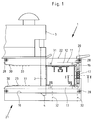
Figur 1- die Vorrichtung in Vorderansicht während eines Arbeitsvorganges mit einem eingespannten Hohlprofil,
Figur 2- einen Schnitt nach der Linie II - II der
Figur 1 und Figur 3- die Vorrichtung nach
Figur 1 in Seitenansicht, in einem vergrößerten Maßstab.
- Figure 1
- the device in front view during a working process with a clamped hollow profile,
- Figure 2
- a section along the line II - II of Figure 1 and
- Figure 3
- the device of Figure 1 in side view, on an enlarged scale.
Die in den Figuren 1 und 3 dargestellte und jeweils mit 1 bezeichnete Vorrichtung dient zum maßgenauen winkeligen Ablängen eines Hohlprofils 2 mittels eines von Hand betätigten Werkzeuges, z. B. einer Stichsäge 3, und besteht im wesentlichen aus einer Spanneinrichtung 11 zur Halterung des Hohlprofils 2 während dessen Bearbeitung und einem Führungsglied 21, mittels dem das Sägeblatt 4 der Stichsäge 3 beim Sägevorgang oberhalb und unterhalb des Hohlprofils 2 exakt geführt ist. Ein Verlaufen des Sägeblattes 4 ist dadurch nahezu ausgeschlossen, eine saubere Schnittkante ist vielmehr durch die Führung des Sägeblattes 4 gewährleistet.The device shown in Figures 1 and 3 and each designated 1 is used for accurate angular cutting to length of a
Die Spanneinrichtung 11 besteht, wie dies insbesondere der Figur 3 zu entnehmen ist, aus zwei winkelig gestalteten Spannplatten 12 und 13, die somit das Hohlprofil 2 teilweise umgreifen und die zu dessen Einspannung gegeneinander verstellbar sind. Dazu sind in zwei in die Spannplatte 13 eingearbeitete Bohrungen 14 Führungsbolzen 16 eingesetzt, die in die Spannplatte 12 eingearbeitete Bohrungen 15 eingreifen, so daß die Spannplatte 12 auf diesen entgegen der Kraft von ebenfalls in die abgestuft ausgebildeten Bohrungen 15 eingesetzten Federn 17 in Richtung des Hohlprofiles 2 verstellbar gehalten ist. Und mittels einer mittig angeordneten Spannschraube 20, die in eine in der Spannplatte 13 vorgesehenen Gewindebohrung 18 eingreift und durch eine in die Spannplatte 12 eingearbeitete Bohrung 19 hindurchgeführt ist, sind die beiden Spannplatten 12 und 13 gegeneinander verstellbar, so daß das Hohlprofil 2 zwischen diesen eingespannt werden kann und während des Arbeitsvorganges sicher gehalten ist.The
Das Führungsglied 21 ist durch zwei Schienen 22 und 23 gebildet, die parallel zueinander angeordnet und mittels Schrauben 31 fest mit den Spannplatten 12 bzw. 13 der Spanneinrichtung 11 verbunden sind. Die Schienen 22 und 23, die bei dem gezeigten Ausführungsbeispiel rechtwinklig zu dem einzuspannenden Hohlprofil 2 von den Spannplatten 12 und 13 abstehen, weisen jeweils einen in einer gemeinsamen Ebene verlaufenden Schlitz 24 bzw. 25 auf, in denen das Sägeblatt 4 der Stichsäge 3, wie dies in Figur 1 gezeigt ist, während eines Sägevorganges geführt ist.The
Die Schienen 22 und 23 bestehen jeweils aus zwei Leisten 26 und 27, zwischen denen in den Endbereichen Distanzstücke 28 eingesetzt und die durch Schrauben 29 fest miteinander verbunden sind. Auf diese Weise sind die Schienen 22 und 23 auf wirtschaftliche Weise herzustellen. Des weiteren sind die Schienen 22 und 23 jeweils mit einer Einführschräge 30 versehen und können, wie dies in Figur 1 strichpunktiert eingezeichnet ist, um Beschädigungen des Hohlprofils 2 zu vermeiden, mit einer Beschichtung 23 ausgestattet werden. Und um die Vorrichtung 1 betriebssicher abstützen zu können, ist an der Spannplatte 13 der Spanneinrichtung 11 eine Auflage 10 in Form einer Platte mittels Schrauben 32 befestigt.The
Claims (8)
gekennzeichnet durch
eine Spanneinrichtung (11) zur Halterung des Hohlprofils (2) und einem mit dieser verbundenen, an das abzulängende Hohlprofil (2) anlegbaren Führungsglied (21), das auf zwei einander gegenüberliegenden Seiten in einer gemeinsamen Ebene verlaufende Führungsschlitze (24, 25) zur Aufnahme des Sägeblattes (4) der Stichsäge (3) aufweist.Device (1) for cutting hollow profiles (2), in particular duct profiles made of sheet steel for parapet ducts, by means of a jigsaw (3) to be guided by hand or a similar tool,
marked by
a tensioning device (11) for holding the hollow profile (2) and a guide member (21) connected to it and attachable to the hollow profile (2) to be cut to length, the guide slots (24, 25) running on two opposite sides in a common plane for receiving of the saw blade (4) of the jigsaw (3).
dadurch gekennzeichnet,
daß die Spanneinrichtung (11) aus zwei gegeneinander verstellbar angeordneten vorzugsweise winkelförmig gestalteten Spannplatten (12, 13) besteht, zwischen denen das abzulängende Hohlprofil (2) einspannbar ist.Device according to claim 1,
characterized,
that the clamping device (11) consists of two mutually adjustable, preferably angularly designed clamping plates (12, 13), between which the hollow profile (2) to be cut can be clamped.
dadurch gekennzeichnet,
daß die Spannplatten (12, 13) über in diese eingesetzte Führungsbolzen (16) oder dgl. verstellbar miteinander verbunden und mittels einer oder mehrerer Spannschrauben (20) vorzugsweise entgegen der Kraft von auf den Führungsbolzen (16) gehaltener Druckfedern (17) verspannbar sind.Device according to claim 2,
characterized,
that the clamping plates (12, 13) are adjustably connected to one another via guide pins (16) or the like inserted therein and can be braced by means of one or more clamping screws (20), preferably against the force of compression springs (17) held on the guide pins (16).
dadurch gekennzeichnet,
daß das Führungsglied (21) durch zwei an den Spannplatten (12, 13) angebrachten, vorzugsweise achssenkrecht zu dem abzulängenden Hohlprofil (2) verlaufenden und winkelförmig gestalteten Schienen (22, 23) gebildet ist, in die die in einer gemeinsamen Ebene angeordneten Schlitze (24, 25) zur Aufnahme des Sägeblattes (4) eingearbeitet sind.Device according to one or more of claims 1 to 3,
characterized,
that the guide member (21) is formed by two angularly shaped rails (22, 23) attached to the clamping plates (12, 13), preferably axially perpendicular to the hollow profile (2) to be cut, into which the slots () arranged in a common plane ( 24, 25) are incorporated to accommodate the saw blade (4).
dadurch gekennzeichnet,
daß die Schienen (22, 23) jeweils durch zwei mit seitlichem Abstand zueinander angeordnete Leisten (26, 27) gebildet sind, zwischen denen in den beiden Endbereichen Distanzstücke (28) eingesetzt sind.Device according to claim 4,
characterized,
that the rails (22, 23) are each formed by two strips (26, 27) arranged at a lateral distance from one another, between which spacers (28) are inserted in the two end regions.
dadurch gekennzeichnet,
daß das Führungsglied durch einen U-förmigen oder geschlossenen Rahmen gebildet ist, in dessen in der Ebene der Spannplatten (12, 13) angeordnete Schenkel jeweils ein Schlitz zur Aufnahme des Sägeblattes (4) eingearbeitet ist.Device according to one or more of claims 1 to 3,
characterized,
that the guide member is formed by a U-shaped or closed frame, in the legs arranged in the plane of the clamping plates (12, 13) each a slot for receiving the saw blade (4) is machined.
dadurch gekennzeichnet,
daß eine oder beide Schienen (22, 23) bzw. die Schenkel des U-förmigen Rahmens mit einer Einführschräge (30) und/oder ganz oder teilweise mit einer Beschichtung (33) versehen sind.Device according to one or more of claims 4 to 6,
characterized,
that one or both rails (22, 23) or the legs of the U-shaped frame are provided with an insertion bevel (30) and / or in whole or in part with a coating (33).
dadurch gekennzeichnet,
daß an eine der Spannplatten (13) der Spanneinrichtung (11) eine plattenförmige Auflage (10) befestigt ist, an der das Führungsglied (21) mit der zugeordneten Schiene (23) bzw. dem zugeordneten Schenkel an einer Stirnseite anliegt.Device according to one or more of claims 1 to 7,
characterized,
that a plate-shaped support (10) is attached to one of the clamping plates (13) of the clamping device (11), on which the guide member (21) with the associated rail (23) or the associated leg rests on one end face.
Applications Claiming Priority (2)
| Application Number | Priority Date | Filing Date | Title |
|---|---|---|---|
| DE9217392U | 1992-12-19 | ||
| DE9217392U DE9217392U1 (en) | 1992-12-19 | 1992-12-19 | Device for cutting hollow profiles |
Publications (2)
| Publication Number | Publication Date |
|---|---|
| EP0603625A1 true EP0603625A1 (en) | 1994-06-29 |
| EP0603625B1 EP0603625B1 (en) | 1999-04-07 |
Family
ID=6887348
Family Applications (1)
| Application Number | Title | Priority Date | Filing Date |
|---|---|---|---|
| EP93119639A Expired - Lifetime EP0603625B1 (en) | 1992-12-19 | 1993-12-06 | Device for cutting at length hollow structural members |
Country Status (3)
| Country | Link |
|---|---|
| EP (1) | EP0603625B1 (en) |
| AT (1) | ATE178518T1 (en) |
| DE (2) | DE9217392U1 (en) |
Cited By (2)
| Publication number | Priority date | Publication date | Assignee | Title |
|---|---|---|---|---|
| EP0826453A1 (en) * | 1996-08-27 | 1998-03-04 | Kambo AG | Equipment for a jigsaw |
| EP2436468A1 (en) * | 2010-09-29 | 2012-04-04 | Black & Decker Inc. | Reciprocating Saw |
Families Citing this family (4)
| Publication number | Priority date | Publication date | Assignee | Title |
|---|---|---|---|---|
| DE29608100U1 (en) * | 1996-05-07 | 1996-08-08 | Schefe Ines | Device for cutting hollow profiles |
| DE102008002076A1 (en) | 2008-05-29 | 2009-12-03 | Hilti Aktiengesellschaft | Holding device for hollow profile, has clamping device for fixing profile in profile retainer and arranged at one of wall sections, and gripping part displaceable by operating part for fixing profile to side of section |
| DE102011082476A1 (en) * | 2011-09-12 | 2013-03-14 | Hilti Aktiengesellschaft | handle |
| DE102016000180B3 (en) * | 2016-01-11 | 2017-05-11 | Dietmar Schefe | Guide device for jigsaws |
Citations (4)
| Publication number | Priority date | Publication date | Assignee | Title |
|---|---|---|---|---|
| US2003619A (en) * | 1933-05-10 | 1935-06-04 | Trimont Mfg Co Inc | Pipe cutting device |
| US2111468A (en) * | 1935-11-27 | 1938-03-15 | Leo M Corkum | Hacksaw guide |
| DE1676058U (en) * | 1953-07-30 | 1954-05-13 | Neue Molkereitechnik G M B H | CLAMPING AND GUIDE TOOL FOR SAWING PIPES. |
| FR2579923A1 (en) * | 1985-04-05 | 1986-10-10 | Guiu Claude | Guide slit for apparatus for cutting a bevel in a component |
-
1992
- 1992-12-19 DE DE9217392U patent/DE9217392U1/en not_active Expired - Lifetime
-
1993
- 1993-12-06 EP EP93119639A patent/EP0603625B1/en not_active Expired - Lifetime
- 1993-12-06 AT AT93119639T patent/ATE178518T1/en not_active IP Right Cessation
- 1993-12-06 DE DE59309500T patent/DE59309500D1/en not_active Expired - Fee Related
Patent Citations (4)
| Publication number | Priority date | Publication date | Assignee | Title |
|---|---|---|---|---|
| US2003619A (en) * | 1933-05-10 | 1935-06-04 | Trimont Mfg Co Inc | Pipe cutting device |
| US2111468A (en) * | 1935-11-27 | 1938-03-15 | Leo M Corkum | Hacksaw guide |
| DE1676058U (en) * | 1953-07-30 | 1954-05-13 | Neue Molkereitechnik G M B H | CLAMPING AND GUIDE TOOL FOR SAWING PIPES. |
| FR2579923A1 (en) * | 1985-04-05 | 1986-10-10 | Guiu Claude | Guide slit for apparatus for cutting a bevel in a component |
Cited By (3)
| Publication number | Priority date | Publication date | Assignee | Title |
|---|---|---|---|---|
| EP0826453A1 (en) * | 1996-08-27 | 1998-03-04 | Kambo AG | Equipment for a jigsaw |
| EP2436468A1 (en) * | 2010-09-29 | 2012-04-04 | Black & Decker Inc. | Reciprocating Saw |
| US8776383B2 (en) | 2010-09-29 | 2014-07-15 | Black & Decker Inc. | Clamp for reciprocating saw |
Also Published As
| Publication number | Publication date |
|---|---|
| DE59309500D1 (en) | 1999-05-12 |
| ATE178518T1 (en) | 1999-04-15 |
| EP0603625B1 (en) | 1999-04-07 |
| DE9217392U1 (en) | 1994-04-14 |
Similar Documents
| Publication | Publication Date | Title |
|---|---|---|
| DE3806116A1 (en) | DEVICE FOR POSITIONING ARC-SHAPED CROSSBODY FRAME PARTS AND MILLING KEYSTONE EXCEPTIONS IN THESE FRAME PARTS | |
| DE2702992C2 (en) | Machining device | |
| EP0603625B1 (en) | Device for cutting at length hollow structural members | |
| EP2018922A2 (en) | Circular saw stand | |
| DE1453213B2 (en) | ||
| AT409606B (en) | PANEL | |
| EP0674962B1 (en) | Device for cutting at length hollow structural members | |
| EP1679150B1 (en) | Device for drilling holes in elongated work pieces | |
| EP0585423B1 (en) | Clamp for a pipe cutting machine | |
| EP1800783A1 (en) | Cutting table and method for cutting profile sections | |
| DE3103722C2 (en) | Stop device for woodworking machines | |
| EP1563964A1 (en) | Auxiliary device for machining workpieces | |
| EP0807483B1 (en) | Device for cutting to length hollow structural members | |
| EP0623420A1 (en) | Transporting and locating device | |
| DE3918710C2 (en) | Miter saw for glass holding strips | |
| DE4320622A1 (en) | Device for cutting hollow sections to length | |
| DE4037614C1 (en) | Powered guiding appts. for machining workpieces - has positioning stop pivoted to protractor adjustable along guide rail | |
| EP0339177A2 (en) | Sawing device | |
| DE2059558C3 (en) | Adjustable end stop | |
| DE2939769C2 (en) | Guide device for saws, in particular for hand-held circular saws | |
| DE4415904C2 (en) | Device for guiding a hand-held machine tool | |
| DE3536830A1 (en) | Router for working wood or plastic | |
| DE4224052C2 (en) | Stop angle for manual machine | |
| DE7702782U1 (en) | Saw for stone workpieces | |
| DE2025374A1 (en) | Device for the stationary operation of rotating tools used in a motor-driven hand drill |
Legal Events
| Date | Code | Title | Description |
|---|---|---|---|
| PUAI | Public reference made under article 153(3) epc to a published international application that has entered the european phase |
Free format text: ORIGINAL CODE: 0009012 |
|
| AK | Designated contracting states |
Kind code of ref document: A1 Designated state(s): AT CH DE ES FR GB IT LI SE |
|
| 17P | Request for examination filed |
Effective date: 19941214 |
|
| 17Q | First examination report despatched |
Effective date: 19970120 |
|
| GRAG | Despatch of communication of intention to grant |
Free format text: ORIGINAL CODE: EPIDOS AGRA |
|
| GRAG | Despatch of communication of intention to grant |
Free format text: ORIGINAL CODE: EPIDOS AGRA |
|
| GRAH | Despatch of communication of intention to grant a patent |
Free format text: ORIGINAL CODE: EPIDOS IGRA |
|
| GRAH | Despatch of communication of intention to grant a patent |
Free format text: ORIGINAL CODE: EPIDOS IGRA |
|
| GRAA | (expected) grant |
Free format text: ORIGINAL CODE: 0009210 |
|
| AK | Designated contracting states |
Kind code of ref document: B1 Designated state(s): AT CH DE ES FR GB IT LI SE |
|
| PG25 | Lapsed in a contracting state [announced via postgrant information from national office to epo] |
Ref country code: SE Free format text: THE PATENT HAS BEEN ANNULLED BY A DECISION OF A NATIONAL AUTHORITY Effective date: 19990407 Ref country code: IT Free format text: LAPSE BECAUSE OF FAILURE TO SUBMIT A TRANSLATION OF THE DESCRIPTION OR TO PAY THE FEE WITHIN THE PRE;WARNING: LAPSES OF ITALIAN PATENTS WITH EFFECTIVE DATE BEFORE 2007 MAY HAVE OCCURRED AT ANY TIME BEFORE 2007. THE CORRECT EFFECTIVE DATE MAY BE DIFFERENT FROM THE ONE RECORDED.SCRIBED TIME-LIMIT Effective date: 19990407 Ref country code: GB Free format text: LAPSE BECAUSE OF NON-PAYMENT OF DUE FEES Effective date: 19990407 Ref country code: FR Free format text: LAPSE BECAUSE OF FAILURE TO SUBMIT A TRANSLATION OF THE DESCRIPTION OR TO PAY THE FEE WITHIN THE PRESCRIBED TIME-LIMIT Effective date: 19990407 Ref country code: ES Free format text: THE PATENT HAS BEEN ANNULLED BY A DECISION OF A NATIONAL AUTHORITY Effective date: 19990407 |
|
| REF | Corresponds to: |
Ref document number: 178518 Country of ref document: AT Date of ref document: 19990415 Kind code of ref document: T |
|
| REG | Reference to a national code |
Ref country code: CH Ref legal event code: EP |
|
| REF | Corresponds to: |
Ref document number: 59309500 Country of ref document: DE Date of ref document: 19990512 |
|
| EN | Fr: translation not filed | ||
| GBV | Gb: ep patent (uk) treated as always having been void in accordance with gb section 77(7)/1977 [no translation filed] |
Effective date: 19990407 |
|
| PG25 | Lapsed in a contracting state [announced via postgrant information from national office to epo] |
Ref country code: AT Free format text: LAPSE BECAUSE OF NON-PAYMENT OF DUE FEES Effective date: 19991206 |
|
| PG25 | Lapsed in a contracting state [announced via postgrant information from national office to epo] |
Ref country code: LI Free format text: LAPSE BECAUSE OF NON-PAYMENT OF DUE FEES Effective date: 19991231 Ref country code: CH Free format text: LAPSE BECAUSE OF NON-PAYMENT OF DUE FEES Effective date: 19991231 |
|
| PLBE | No opposition filed within time limit |
Free format text: ORIGINAL CODE: 0009261 |
|
| STAA | Information on the status of an ep patent application or granted ep patent |
Free format text: STATUS: NO OPPOSITION FILED WITHIN TIME LIMIT |
|
| 26N | No opposition filed | ||
| PGFP | Annual fee paid to national office [announced via postgrant information from national office to epo] |
Ref country code: DE Payment date: 20010216 Year of fee payment: 8 |
|
| PG25 | Lapsed in a contracting state [announced via postgrant information from national office to epo] |
Ref country code: DE Free format text: LAPSE BECAUSE OF NON-PAYMENT OF DUE FEES Effective date: 20020702 |