EP2436468A1 - Scie alternative - Google Patents
Scie alternative Download PDFInfo
- Publication number
- EP2436468A1 EP2436468A1 EP11183145A EP11183145A EP2436468A1 EP 2436468 A1 EP2436468 A1 EP 2436468A1 EP 11183145 A EP11183145 A EP 11183145A EP 11183145 A EP11183145 A EP 11183145A EP 2436468 A1 EP2436468 A1 EP 2436468A1
- Authority
- EP
- European Patent Office
- Prior art keywords
- housing
- shoe
- facing surface
- material facing
- reciprocating saw
- Prior art date
- Legal status (The legal status is an assumption and is not a legal conclusion. Google has not performed a legal analysis and makes no representation as to the accuracy of the status listed.)
- Withdrawn
Links
Images


Classifications
-
- B—PERFORMING OPERATIONS; TRANSPORTING
- B23—MACHINE TOOLS; METAL-WORKING NOT OTHERWISE PROVIDED FOR
- B23D—PLANING; SLOTTING; SHEARING; BROACHING; SAWING; FILING; SCRAPING; LIKE OPERATIONS FOR WORKING METAL BY REMOVING MATERIAL, NOT OTHERWISE PROVIDED FOR
- B23D49/00—Machines or devices for sawing with straight reciprocating saw blades, e.g. hacksaws
- B23D49/10—Hand-held or hand-operated sawing devices with straight saw blades
- B23D49/16—Hand-held or hand-operated sawing devices with straight saw blades actuated by electric or magnetic power or prime movers
- B23D49/162—Pad sawing devices
- B23D49/167—Pad sawing devices with means to adjust the guide plate or with means to adjust the plane in which the saw blade moves
-
- B—PERFORMING OPERATIONS; TRANSPORTING
- B23—MACHINE TOOLS; METAL-WORKING NOT OTHERWISE PROVIDED FOR
- B23D—PLANING; SLOTTING; SHEARING; BROACHING; SAWING; FILING; SCRAPING; LIKE OPERATIONS FOR WORKING METAL BY REMOVING MATERIAL, NOT OTHERWISE PROVIDED FOR
- B23D49/00—Machines or devices for sawing with straight reciprocating saw blades, e.g. hacksaws
- B23D49/10—Hand-held or hand-operated sawing devices with straight saw blades
- B23D49/16—Hand-held or hand-operated sawing devices with straight saw blades actuated by electric or magnetic power or prime movers
- B23D49/162—Pad sawing devices
-
- B—PERFORMING OPERATIONS; TRANSPORTING
- B23—MACHINE TOOLS; METAL-WORKING NOT OTHERWISE PROVIDED FOR
- B23D—PLANING; SLOTTING; SHEARING; BROACHING; SAWING; FILING; SCRAPING; LIKE OPERATIONS FOR WORKING METAL BY REMOVING MATERIAL, NOT OTHERWISE PROVIDED FOR
- B23D51/00—Sawing machines or sawing devices working with straight blades, characterised only by constructional features of particular parts; Carrying or attaching means for tools, covered by this subclass, which are connected to a carrier at both ends
- B23D51/04—Sawing machines or sawing devices working with straight blades, characterised only by constructional features of particular parts; Carrying or attaching means for tools, covered by this subclass, which are connected to a carrier at both ends of devices for feeding, positioning, clamping, or rotating work
Definitions
- the present invention relates to reciprocating saws and more particularly to a clamp assembly on a reciprocating saw.
- a conventional reciprocating saw or jigsaw can generally consist of a housing having a motor, a drive mechanism for translating rotational motion of the motor into linear actuation of a carrier or driveshaft, and a saw blade releasably coupled to the drive shaft.
- a user may use a reciprocating saw to cut cylindrical objects, such as pipes for example.
- the user can hold the saw at a handle portion and bring the reciprocating saw blade into contact with the cylindrical piece.
- the reciprocating saw blade can slowly be moved through the cylindrical item while cutting it.
- the reciprocating movements of the saw blade can exert forces on the object which is being cut, i.e., the pipe.
- the object being cut can try to follow the saw blade since there can be a considerable friction between the reciprocating saw blade and the pipe. Therefore, in some instances, a user can grip the pipe and hold it tightly with one hand against the saw while the reciprocating saw is held in the other hand in order to achieve an accurate cut.
- Such a scenario can present an inconvenient cutting experience.
- the cut can be inaccurate if the reciprocating saw blade is not steadily held in the same position with respect to the pipe.
- a reciprocating saw constructed in accordance with one aspect of the present invention can include a housing and a motor disposed in the housing.
- a blade retaining mechanism can receive a saw blade.
- a drive mechanism can translate rotational motion of the motor into reciprocating motion of the blade retaining mechanism.
- a clamp assembly can include first and second shoes that are coupled to the housing.
- the first shoe can have a first shoe body that includes a first material facing surface.
- the second shoe can include a second material facing surface that opposes the first material facing surface and that defines a clamping distance therebetween. At least one of the first and second shoes is selectively adjustable relative to the housing, such that the clamping distance can be altered.
- One of the first or second shoe bodies preferably can have a third material facing surface that comprises an arcuate section defining a radius.
- the second shoe body preferably can comprise the arcuate section that has the third material facing surface.
- the second shoe body preferably can be selectively adjustable relative to the housing.
- the third material facing surface preferably can be oriented in an unopposing relationship to a cutting surface of the saw blade.
- the second shoe body preferably can be selectively adjustable to a location where the clamping distance is at least as large as two times the radius.
- the second shoe body preferably can be selectively adjustable to a location where the clamping distance is at least 1.5 inches.
- the radius preferably can comprise substantially about 0.75 inches, such that the arcuate section can accommodate an object being cut that has a diameter of substantially about 1.5 inches.
- Both of the first and second shoe bodies preferably can define an opening for receiving the saw blade.
- the second shoe preferably can further comprise a connection portion that connects the second shoe body to the housing.
- the connection portion preferably can have a longitudinal body including a longitudinal opening that extends substantially transverse to the second material facing surface.
- a securing bolt preferably can locate through the longitudinal opening and be selectively locked to the housing.
- the first shoe body preferably can also be selectively adjustable relative to the housing resulting in changing of the clamping distance.
- the second shoe body preferably can include a cylindrical member that selectively locates in one of a plurality of grooves formed on the housing.
- the clamping distance preferably can alter based on the cylindrical member being located in a selected groove of the plurality of grooves.
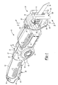
- the reciprocating saw 10 can include a housing 12 having a motor 14, a drive mechanism 16, a blade retaining mechanism 18 and a clamp assembly 20.
- the drive mechanism 16 can be configured to translate rotational motion of the motor 14 into linear actuation of a drive shaft 26.
- the blade retaining mechanism 18 can releasably couple a saw blade 30 to the drive shaft 26.
- the housing 12 can generally comprise a first clam shell portion 32 and a second clam shell portion 34 that are secured to each other by a series of fasteners 38.
- the housing 12 can define a cavity 40 that receives a battery 42.
- a power switch 44 and a trigger 46 can each extend through openings 48 and 50, respectively formed in the housing 12.
- the housing 12 can further comprise a handle 54 that has a gripping portion 56.
- the trigger 46 can be configured to communicate a voltage from the battery 42 to the motor 14.
- the exemplary reciprocating saw 10 is shown as a battery-powered embodiment, the principles of the present disclosure can also be adapted for use with a corded, alternating current reciprocating saw.
- the clamp assembly 20 can generally comprise a first or lower fixed shoe 60 and a second or upper movable shoe 62.
- the lower fixed shoe 60 can be fixedly connected to the housing 12, such as by fasteners or can be formed at least in part by an extension of the housing 12.
- the lower fixed shoe can generally comprise a fixed shoe body 66 having a connection portion 68 and a clamping portion 70.
- the clamping portion 70 can comprise a material facing surface 72 that defines an opening 74 ( Fig. 5 ) for receiving the saw blade 30.
- the upper movable shoe 62 can generally comprise a movable shoe body 76 having a connection portion 78 ( Fig. 4 ) and a clamping portion 80.
- An arcuate section 82 can be provided on the movable shoe body 76.
- Indicia 83 can be provided on the connecting portion 78.
- the arcuate section 82 can have a material facing surface 84 that defines a radius 86 ( Fig. 7 ) for accommodating various objects to be cut.
- the arcuate section 82 can more generally comprise a central section that is offset away from the saw blade 30 relative to other portions of the upper movable shoe 62, such as the connection portion 78.
- the arcuate section 82 can alternatively comprise a polygonal shape or combination of straight and arcuate sections.
- the connecting portion 78 further includes a longitudinal body 90 that can be slidably extended and retracted from a slot 94 ( Fig. 3 ) provided in the housing 12.
- the longitudinal body 90 can define a longitudinal opening 96 ( Fig. 4 ) that can receive a securing bolt 100 ( Fig. 3 ) that is threadably coupled to the housing 12.
- the clamping portion 80 of the movable shoe body 76 can include a material facing surface 102 that generally opposes the material facing surface 72 of the fixed shoe body 66.
- An opening 104 can be formed through the clamping portion 80 that corresponds to and aligns with the opening 74 for receiving the saw blade 30.
- a clamping distance 106 ( Fig. 6 ) can be defined between the material clamping surfaces 72 and 102 of the fixed shoe body 66 and the movable shoe body 76, respectively.
- the arcuate section 82 of the movable shoe body 76 can progressively receive an object being cut, such as any of the various exemplary pipes 120a, 120b and 120c.
- the exemplary pipe 120a can have a diameter of one and a half inches
- the pipe 120b can have a diameter of three-quarter inch
- the pipe 120c can have a diameter of one-quarter inch.
- the clamp assembly 20 can provide a geometrical configuration that allows a relatively large pipe (such as pipe 120a) to be placed initially between the material facing surfaces 72 of the fixed shoe 60 and the material facing surface 102 of the movable shoe 62.
- the arcuate section 82 can accommodate an outer surface of the pipe being cut (such as the pipe 120a) subsequent to a cutting surface 122 of the saw blade 30 passing completely through the pipe 120a (see Fig. 7 ).
- the upper movable shoe 62 can be adjusted to a location where the clamping distance 106 is at least as large as two times the radius 86 of the arcuate section 82 of the movable shoe body 76.
- the radius 86 can be substantially about the three-quarter inch and the upper movable shoe 62 can be adjusted to a location where the clamp distance is substantially about one and a half inches.
- the material facing surface 84 is oriented in an unopposing relationship to the cutting surface 122. Once the cutting surface 122 of the saw blade 30 has sufficiently cut through the pipe 120a, the arcuate section 82, and more specifically the material facing surface 84 can oppose, and in some examples, engage a portion of the remaining pipe 120a. It will be appreciated that a distance 123 ( Fig. 7 ) measured between an apex of the material facing surface 84 and the cutting surface 122 can be at least as large as two times the radius 86 (or at least as large as the diameter of the pipe 120a) ensuring the pipe 120a has been cut completely through prior to potentially engaging the material facing surface 84.
- a user can be offered greater control of the reciprocating saw 10 even subsequent to the pipe 120a being completely cut through.
- the respective material facing surface 72 of the fixed shoe 60 and the material facing surface 102 of the movable shoe 62 can progressively guide the pipe (120a, etc.) into the cutting surface 122 of the saw blade 30 providing greater control of the reciprocating saw 10 from initial positioning of the clamp assembly 20 around the pipe 120a ( Fig. 6 ), as well as during cutting of the pipe 120a. In this way, vibrations transmitted from the saw blade 30 onto the pipe 120a can be controlled and minimized by the fixed shoe 60 and the movable shoe 62.
- a user can extend the upper movable shoe 62 outwardly (in a direction rightward as viewed from Fig. 6 ) until the clamping distance 106 is substantially equivalent to a diameter of the pipe (120a, 120b, 120c, etc.) to be cut.
- a user must first loosen the securing bolt 100 ( Fig. 3 ) on the housing 12, such that the upper movable shoe 62 can be extended out of the slot 94 while the securing bolt 100 travels along the longitudinal opening 96 of the movable shoe 62.
- the indicia 83 can alternatively or additionally be referenced off of a forward face 124 ( Fig.
- the housing 12 can match a diameter of the pipe being cut.
- the user can tighten the securing bolt 100 to the housing 12 to lock the movable shoe 62 in a fixed position.
- a user can move the cutting surface 122 of the saw blade 30 into contact with the pipe (120a, 120b, 120c, etc.) being cut and concurrently or subsequently depress the trigger 46 to activate the motor 14 and begin cutting.
- the cutting action is continued until the cutting surface 122 of the saw blade 30 has passed entirely through the pipe being cut ( Fig. 7 ).
- the profile of the pipe being cut such as the pipe 120a illustrated in Fig. 7 is accommodated by the arcuate section 82 of the movable shoe 62.
- the material facing surface 84 of the arcuate section 82 can engage the pipe (120a, etc.) that has been cut entirely through. While the specific example illustrated includes a pipe 120a having a diameter of one and a half inches, the clamp assembly 20 can be configured differently, such as having an arcuate section 82 that provides a greater radius 86 to accommodate pipes having larger diameters.
- the connection portion 78 can be longer such that a larger clamping distance 106 can be attained.
- the arcuate section 82 can also provide the user with increased control over the reciprocating saw 10 as a whole by the contact of the material facing surface 84 on the arcuate section 82 with the pipe 120a. In this regard, such engagement between the material facing surface 84 of the arcuate section 82 can minimize a user's tendency to urge the reciprocating saw 10 further toward a cutting direction after cutting has been completed.
- a forward positioning surface 126 on the movable shoe 62 can be used as a reference on a work piece when the depth of cut attained by the saw blade 30 needs to be controlled.
- a user can adjust the movable shoe 62 with the securing bolt 100 as described above to a desired location that corresponds to a cut depth 127 ( Fig. 7 ) measured from a distal cutting tip 128 of the saw blade 30 at its furthest extension of the cutting stroke.
- a user can position the forward positioning surface 126 against a work piece, such as drywall for example, while cutting through the drywall with the cutting surface 122 of the saw blade 30.
- the forward positioning surface 126 on the movable shoe 62 can also be used to limit the amount of cutting surface 122 that engages a work piece. For example, in some instances, teeth near the blade retaining mechanism 18 may become dull as compared to teeth near the tip 128 of the saw blade 30. By moving the movable shoe 62 forward (toward the tip 128) the cutting stroke can be limited to exposure to teeth closer to the distal cutting tip 128.
- a notch 129 can also be incorporated on the movable shoe 62. The notch 129 can be used to pull nails or tacks.
- the lower adjustable shoe 130 can generally comprise an adjustable shoe body 132 having a clamping portion 134 and a connecting portion 136.
- the clamping portion 134 can have a material engaging surface 140 and define an opening 142 that receives the saw blade 30.
- the connecting portion 136 can define an elongated passage 146 that selectively receives an adjusting bolt 150 that is threadably received by the housing 12.
- the adjustable shoe body 132 can be formed as a unitary piece or alternatively can be formed by separate sections including the clamping portion 134 and connecting portion 136 that are coupled together, such as by a welding operation.
- the lower adjustable shoe 130 can slidably adjust relative to the housing 12 similar to the upper movable shoe 62 described above. Specifically, the fastener 150 can be loosened and the connecting portion 136 can slidably adjust through an opening 162 formed in the housing 12. Once the desired location has been attained, a user can tighten the fastener 150, such that a head of the fastener 150 fixedly secures the connecting portion 136 to the housing 12. It will be appreciated that a user may additionally or alternatively desire to adjust the upper movable shoe 62 to achieve a desired clamp distance 166.
- the reciprocating saw 210 and the clamp assembly 220 can be constructed similarly to the reciprocating saw 10 and the clamp assembly 20 described above.
- the clamp assembly 220 can generally comprise a first or lower fixed shoe 222 and a second or upper movable shoe 224.
- the lower fixed shoe 222 can be fixedly connected to a housing 212 of the reciprocating saw 210, such as by fasteners or can be formed at least in part by an extension of the housing 212.
- the lower fixed shoe can generally comprise a fixed shoe body 230 having a connection portion 232 and a clamping portion 234.
- the clamping portion 234 can comprise a material facing surface 240.
- a carrier 242 can be formed at least in part by the fixed shoe body 230 of the lower fixed shoe 222.
- the carrier 242 can additionally or alternatively be formed as part of the housing 212.
- the carrier 242 can define a bore 244 that defines an axis 246.
- the housing 212 can include a locating body 214 that has a plurality of grooves collectively referred to at reference numeral 216 and individually identified at reference numerals 216a, 216b, 216c and 216d.
- the upper movable shoe 224 can generally comprise a movable shoe body 250.
- the body 250 can be formed by a cylindrical member 252.
- the cylindrical member 252 can be a steel spring to provide a snap fit with the grooves 216.
- the cylindrical member 252 can be formed of other materials such as entirely or partially with elastomeric material.
- the cylindrical member 252 can have a clamping portion 256, an arcuate section 258 and a connection portion 260.
- the clamping portion 256 can be constructed like the clamping portion 80 ( Fig. 4 ) described above.
- the connection portion 260 can be slidably received by the bore 244 of the carrier 242. In this regard, the connection portion 260 can be slidably extended and retracted from the bore 244 as will be described in greater detail.
- the clamping portion 256 can include a material facing surface 270.
- the arcuate section 258 can include a material facing surface 272.
- the arcuate section 258 can be configured with a geometry, such that a radius 278 defined by the arcuate section 258 can accommodate a diameter of the pipe 120a subsequent to cutting as described above with respect to the clamp assembly 20.
- An exemplary sequence of adjusting the upper movable shoe 224 of the clamp assembly 220 will now be described. Initially, a user can rotate the body 250 of the upper movable shoe 224 around the axis 246 in the direction of arrow 279 away from engagement with the grooves 216.
- the body 250 can then be extended or retracted from the bore 244 in a direction along the axis 246 and to a position where the clamping distance 280 defined between the material facing surfaces 240 and 270 is sufficient to accommodate a diameter of the pipe 120a.
- a user can rotate the body 250 back toward engagement with one of the grooves 216 that will correspond to the desired clamping distance 280.
- the user can then proceed with cutting of the pipe 120a.
- the user can move the cutting surface 122 of the saw blade 30 into contact with the pipe 120a being cut and concurrently or subsequently depress the trigger of the reciprocating saw 210.
- the lower fixed shoe 222 and upper movable shoe 224 are minimized as the pipe 120a is inhibited from lateral movement (leftward or rightward as viewed from Fig. 12 ) by the material facing surface 240 of the lower fixed shoe 222 and the material facing surface 270 of the upper movable shoe 224.
- the cutting action is continued until the cutting surface 122 of the saw blade 30 has passed entirely through the pipe 120a.
- the profile of the pipe being cut, such as the pipe 120a illustrated in Fig. 10 is accommodated by the arcuate section 258 of the upper movable shoe 224.
- the arcuate section 258 can also provide the user with increased control over the reciprocating saw 210 as a whole by the contact of the material engaging surface 272 on the arcuate section 258 with the pipe 120a. In this regard, such engagement between the material engaging surface 272 of the arcuate section 258 can minimize a user's tendency to urge the reciprocating saw 210 further toward a cutting direction after cutting has been completed.
Applications Claiming Priority (1)
| Application Number | Priority Date | Filing Date | Title |
|---|---|---|---|
| US12/893,659 US8776383B2 (en) | 2010-09-29 | 2010-09-29 | Clamp for reciprocating saw |
Publications (1)
| Publication Number | Publication Date |
|---|---|
| EP2436468A1 true EP2436468A1 (fr) | 2012-04-04 |
Family
ID=44719537
Family Applications (1)
| Application Number | Title | Priority Date | Filing Date |
|---|---|---|---|
| EP11183145A Withdrawn EP2436468A1 (fr) | 2010-09-29 | 2011-09-28 | Scie alternative |
Country Status (3)
| Country | Link |
|---|---|
| US (1) | US8776383B2 (fr) |
| EP (1) | EP2436468A1 (fr) |
| CN (1) | CN202291645U (fr) |
Cited By (1)
| Publication number | Priority date | Publication date | Assignee | Title |
|---|---|---|---|---|
| WO2014055490A1 (fr) * | 2012-10-04 | 2014-04-10 | Federal-Mogul Powertrain, Inc. | Procédé permettant de couper des éléments tubulaires et appareil associé |
Families Citing this family (15)
| Publication number | Priority date | Publication date | Assignee | Title |
|---|---|---|---|---|
| US9702153B2 (en) | 2012-02-10 | 2017-07-11 | Milwaukee Electric Tool Corporation | Accessory for a reciprocating saw |
| US10293422B2 (en) | 2012-03-01 | 2019-05-21 | Milwaukee Electric Tool Corporation | Blade for a reciprocating saw |
| US9643267B2 (en) | 2012-03-01 | 2017-05-09 | Milwaukee Electric Tool Corporation | Blade for a reciprocating saw |
| US9421625B2 (en) * | 2012-06-14 | 2016-08-23 | Milwaukee Electric Tool Corporation | Reciprocating saw with adjustable shoe |
| CN103537756B (zh) * | 2012-07-11 | 2017-02-08 | 苏州宝时得电动工具有限公司 | 夹持装置及其操作方法、往复式切割工具 |
| DE102012215457A1 (de) * | 2012-08-31 | 2014-03-06 | Robert Bosch Gmbh | Werkzeugmaschine |
| DE102012218288A1 (de) * | 2012-10-08 | 2014-04-10 | Robert Bosch Gmbh | Motorisch angetriebene Werkzeugmaschine, insbesondere Handwerkzeugmaschine |
| CN103895068B (zh) * | 2012-12-25 | 2016-08-03 | 苏州宝时得电动工具有限公司 | 电动往复锯 |
| CN104381034B (zh) * | 2014-10-30 | 2017-03-22 | 浙江亚特电器有限公司 | 一种园林锯 |
| US9937572B2 (en) * | 2015-04-22 | 2018-04-10 | Wesley Harold Hutchcraft | Blade fan |
| DE102017204318A1 (de) * | 2016-03-30 | 2017-10-05 | Robert Bosch Engineering And Business Solutions Private Limited | Hand-Schneidwerkzeug |
| KR101960261B1 (ko) * | 2016-09-12 | 2019-03-20 | 김근혜 | 고소작업용 톱 |
| USD928578S1 (en) * | 2019-05-09 | 2021-08-24 | Shenzhen Allsight E-business Co., Ltd. | Reciprocating saw |
| JP2022175474A (ja) * | 2021-05-13 | 2022-11-25 | 株式会社マキタ | 往復動切断工具 |
| CN114523154A (zh) * | 2022-04-24 | 2022-05-24 | 启东锋刃工具有限公司 | 一种带有锯条夹紧装置的电动工具 |
Citations (7)
| Publication number | Priority date | Publication date | Assignee | Title |
|---|---|---|---|---|
| DE8507971U1 (de) * | 1985-03-18 | 1985-05-30 | Lytec + Tool GmbH, 6000 Frankfurt | Führungseinrichtung für stangenförmige Werkstücke an Pendelhub- und Säbelsägen |
| US4747212A (en) * | 1985-12-19 | 1988-05-31 | Cavdek Richard S | Plastic pipe cutter |
| FR2611351A1 (fr) * | 1984-08-01 | 1988-09-02 | Foell Remswerk | Scie a guichet comportant un dispositif de serrage |
| DE4104296A1 (de) * | 1991-02-13 | 1992-08-20 | Licentia Gmbh | Einrichtung fuer handgefuehrte stichsaegen zum fuehren und niederhalten des schnittguts |
| EP0603625A1 (fr) * | 1992-12-19 | 1994-06-29 | Dietmar Schefe | Dispositif pour la coupe en longueur de profilés creux |
| US6205897B1 (en) * | 1998-04-08 | 2001-03-27 | Sam W. Carter | Pipe cutter and method of cutting pipe |
| US20100031518A1 (en) * | 2008-08-11 | 2010-02-11 | Fedor John A | Hand held power saw apparatus and method |
Family Cites Families (18)
| Publication number | Priority date | Publication date | Assignee | Title |
|---|---|---|---|---|
| US2568791A (en) * | 1946-06-10 | 1951-09-25 | Cooper Corbet | Portable power-driven hack saw |
| US2645011A (en) * | 1952-04-28 | 1953-07-14 | Allan L Otis | Dehorning device |
| US3449992A (en) * | 1967-03-02 | 1969-06-17 | Charles D Hanaway | Manually-held power-driven pipe cutter |
| US3834019A (en) * | 1972-11-22 | 1974-09-10 | Maremont Corp | Apparatus for cutting exhaust system tubes |
| US4437237A (en) * | 1982-08-06 | 1984-03-20 | Ducret Lucien C | Swing saw for cutting metal conduit |
| DE3428436A1 (de) * | 1984-08-01 | 1986-02-06 | Rems-Werk Christian Föll und Söhne GmbH & Co, 7050 Waiblingen | Tragbare stichsaege |
| US5038473A (en) * | 1990-02-28 | 1991-08-13 | The United States Of America As Represented By The Administrator Of The National Aeronautics And Space Administration | Power saw |
| JPH07108414A (ja) * | 1993-08-20 | 1995-04-25 | Hitachi Koki Co Ltd | レシプロソー |
| US5806187A (en) * | 1995-10-25 | 1998-09-15 | Ducret; Lucien C. | Clamping device |
| US5611146A (en) | 1995-10-25 | 1997-03-18 | Ducret; Lucien C. | Clamping device for use with a hand-held tool |
| CA2228021C (fr) * | 1997-01-31 | 2003-07-22 | Black & Decker Inc. | Scie mecanique alternative et mecanisme de prehension |
| US6553669B2 (en) | 1997-07-07 | 2003-04-29 | Sam W. Carter | Pipe cutter and method of cutting pipe |
| US6067716A (en) * | 1999-03-26 | 2000-05-30 | Carter; Sam W. | Plastic pipe cutter |
| US6484409B2 (en) * | 2000-04-21 | 2002-11-26 | Black & Decker Inc. | Pruner attachment apparatus for a power tool |
| US6751838B1 (en) | 2002-06-21 | 2004-06-22 | Carter | Copper pipe coupler tool and method of coupling |
| US6941660B1 (en) * | 2004-06-24 | 2005-09-13 | Leo Varos | Power hand tool with saw blade and pipe engaging bracket for cutting a pipe |
| JP4635802B2 (ja) | 2004-11-15 | 2011-02-23 | スズキ株式会社 | 切断工具 |
| US8146258B2 (en) * | 2007-06-29 | 2012-04-03 | Paul Shafer | Saw comprising movable guide |
-
2010
- 2010-09-29 US US12/893,659 patent/US8776383B2/en active Active
-
2011
- 2011-09-28 EP EP11183145A patent/EP2436468A1/fr not_active Withdrawn
- 2011-09-29 CN CN 201120509580 patent/CN202291645U/zh not_active Expired - Fee Related
Patent Citations (7)
| Publication number | Priority date | Publication date | Assignee | Title |
|---|---|---|---|---|
| FR2611351A1 (fr) * | 1984-08-01 | 1988-09-02 | Foell Remswerk | Scie a guichet comportant un dispositif de serrage |
| DE8507971U1 (de) * | 1985-03-18 | 1985-05-30 | Lytec + Tool GmbH, 6000 Frankfurt | Führungseinrichtung für stangenförmige Werkstücke an Pendelhub- und Säbelsägen |
| US4747212A (en) * | 1985-12-19 | 1988-05-31 | Cavdek Richard S | Plastic pipe cutter |
| DE4104296A1 (de) * | 1991-02-13 | 1992-08-20 | Licentia Gmbh | Einrichtung fuer handgefuehrte stichsaegen zum fuehren und niederhalten des schnittguts |
| EP0603625A1 (fr) * | 1992-12-19 | 1994-06-29 | Dietmar Schefe | Dispositif pour la coupe en longueur de profilés creux |
| US6205897B1 (en) * | 1998-04-08 | 2001-03-27 | Sam W. Carter | Pipe cutter and method of cutting pipe |
| US20100031518A1 (en) * | 2008-08-11 | 2010-02-11 | Fedor John A | Hand held power saw apparatus and method |
Cited By (2)
| Publication number | Priority date | Publication date | Assignee | Title |
|---|---|---|---|---|
| WO2014055490A1 (fr) * | 2012-10-04 | 2014-04-10 | Federal-Mogul Powertrain, Inc. | Procédé permettant de couper des éléments tubulaires et appareil associé |
| US9862109B2 (en) | 2012-10-04 | 2018-01-09 | Federal-Mogul Powertrain Llc | Method of cutting tubular members and apparatus therefor |
Also Published As
| Publication number | Publication date |
|---|---|
| US20120073148A1 (en) | 2012-03-29 |
| US8776383B2 (en) | 2014-07-15 |
| CN202291645U (zh) | 2012-07-04 |
Similar Documents
| Publication | Publication Date | Title |
|---|---|---|
| US8776383B2 (en) | Clamp for reciprocating saw | |
| US11794262B2 (en) | Reciprocating saw blade | |
| EP2771148B1 (fr) | Outil accessoire planeur pour une tour d'énergie oscillante | |
| JP2014176961A (ja) | 湾曲した切断縁を備える往復動鋸ブレード | |
| US8826788B2 (en) | Work piece guide assembly for table saw | |
| US6256889B1 (en) | Auto glass replacement tool | |
| US8919787B1 (en) | Reciprocating tool attachment assembly and methods | |
| US20050252011A1 (en) | Guide adapter with claw contour | |
| EP2266742A1 (fr) | Scie à main | |
| EP2594360B1 (fr) | Accessoire d'outil pour un outil électrique | |
| US20140260879A1 (en) | Hacksaw Blade for a Power Tool | |
| KR101878952B1 (ko) | 캠 롤러타입 고소작업용 톱 | |
| US9702153B2 (en) | Accessory for a reciprocating saw | |
| US6769147B1 (en) | Multi-use broad bladed knife | |
| WO2018119337A1 (fr) | Guide multifonction pour bord droit | |
| US10654188B2 (en) | Guide foot for an oscillating cutting tool | |
| EP3168008A2 (fr) | Chasse-clou motorisé pourvu d'un ensemble de positionnement de clou | |
| KR20160091522A (ko) | 핸디형 전동공구용 보조기 | |
| US9421625B2 (en) | Reciprocating saw with adjustable shoe | |
| JP2004314296A (ja) | サーベル型鋸装置 | |
| EP1677936B1 (fr) | Bague de defilement de scie sauteuse | |
| US20090066040A1 (en) | Saw gripping device for cutting machine | |
| KR20120001182A (ko) | 전동톱 | |
| WO2019152367A1 (fr) | Scie alternative | |
| CA2747399A1 (fr) | Coupe-tuyau dentele et lame dentelee pour celui-ci |
Legal Events
| Date | Code | Title | Description |
|---|---|---|---|
| PUAI | Public reference made under article 153(3) epc to a published international application that has entered the european phase |
Free format text: ORIGINAL CODE: 0009012 |
|
| AK | Designated contracting states |
Kind code of ref document: A1 Designated state(s): AL AT BE BG CH CY CZ DE DK EE ES FI FR GB GR HR HU IE IS IT LI LT LU LV MC MK MT NL NO PL PT RO RS SE SI SK SM TR |
|
| AX | Request for extension of the european patent |
Extension state: BA ME |
|
| STAA | Information on the status of an ep patent application or granted ep patent |
Free format text: STATUS: THE APPLICATION IS DEEMED TO BE WITHDRAWN |
|
| 18D | Application deemed to be withdrawn |
Effective date: 20121005 |