EP0602491B1 - Installation de transmission et de compression - Google Patents
Installation de transmission et de compression Download PDFInfo
- Publication number
- EP0602491B1 EP0602491B1 EP93119606A EP93119606A EP0602491B1 EP 0602491 B1 EP0602491 B1 EP 0602491B1 EP 93119606 A EP93119606 A EP 93119606A EP 93119606 A EP93119606 A EP 93119606A EP 0602491 B1 EP0602491 B1 EP 0602491B1
- Authority
- EP
- European Patent Office
- Prior art keywords
- gear
- output shaft
- compressor system
- planet
- bearing
- Prior art date
- Legal status (The legal status is an assumption and is not a legal conclusion. Google has not performed a legal analysis and makes no representation as to the accuracy of the status listed.)
- Expired - Lifetime
Links
- 230000005540 biological transmission Effects 0.000 title claims description 27
- 230000002093 peripheral effect Effects 0.000 claims description 3
- 230000000284 resting effect Effects 0.000 claims 1
- 229920002994 synthetic fiber Polymers 0.000 claims 1
- 210000001520 comb Anatomy 0.000 description 5
- 230000002349 favourable effect Effects 0.000 description 4
- 238000013461 design Methods 0.000 description 3
- 238000000034 method Methods 0.000 description 3
- 238000005452 bending Methods 0.000 description 2
- 238000009434 installation Methods 0.000 description 2
- 238000004519 manufacturing process Methods 0.000 description 2
- 238000012545 processing Methods 0.000 description 2
- 230000000717 retained effect Effects 0.000 description 2
- 239000000126 substance Substances 0.000 description 2
- 235000013361 beverage Nutrition 0.000 description 1
- 238000002485 combustion reaction Methods 0.000 description 1
- 238000005056 compaction Methods 0.000 description 1
- 230000006835 compression Effects 0.000 description 1
- 238000007906 compression Methods 0.000 description 1
- 238000010276 construction Methods 0.000 description 1
- 238000011161 development Methods 0.000 description 1
- 238000004512 die casting Methods 0.000 description 1
- 238000005553 drilling Methods 0.000 description 1
- 230000000694 effects Effects 0.000 description 1
- 239000003351 stiffener Substances 0.000 description 1
- 238000012546 transfer Methods 0.000 description 1
- 238000013519 translation Methods 0.000 description 1
- 238000011144 upstream manufacturing Methods 0.000 description 1
Images

Classifications
-
- F—MECHANICAL ENGINEERING; LIGHTING; HEATING; WEAPONS; BLASTING
- F04—POSITIVE - DISPLACEMENT MACHINES FOR LIQUIDS; PUMPS FOR LIQUIDS OR ELASTIC FLUIDS
- F04D—NON-POSITIVE-DISPLACEMENT PUMPS
- F04D25/00—Pumping installations or systems
- F04D25/02—Units comprising pumps and their driving means
- F04D25/028—Units comprising pumps and their driving means the driving means being a planetary gear
-
- F—MECHANICAL ENGINEERING; LIGHTING; HEATING; WEAPONS; BLASTING
- F04—POSITIVE - DISPLACEMENT MACHINES FOR LIQUIDS; PUMPS FOR LIQUIDS OR ELASTIC FLUIDS
- F04D—NON-POSITIVE-DISPLACEMENT PUMPS
- F04D25/00—Pumping installations or systems
- F04D25/16—Combinations of two or more pumps ; Producing two or more separate gas flows
- F04D25/163—Combinations of two or more pumps ; Producing two or more separate gas flows driven by a common gearing arrangement
-
- F—MECHANICAL ENGINEERING; LIGHTING; HEATING; WEAPONS; BLASTING
- F16—ENGINEERING ELEMENTS AND UNITS; GENERAL MEASURES FOR PRODUCING AND MAINTAINING EFFECTIVE FUNCTIONING OF MACHINES OR INSTALLATIONS; THERMAL INSULATION IN GENERAL
- F16H—GEARING
- F16H1/00—Toothed gearings for conveying rotary motion
- F16H1/28—Toothed gearings for conveying rotary motion with gears having orbital motion
Definitions
- the invention relates to a compressor system with a gear transmission switched on in the drive train between a drive unit and a compressor area of the system, this gear transmission comprising a gear housing, in this gear housing a gear input shaft, a main gear close to the input and at least one gear driven from this main gear via a pinion leading to the compressor area Output shaft with one axis.
- the prerequisites for this are the transmission of high torques at medium speeds for the compressor stages compressing at a low pressure level and highest speeds for the compressor stages compressing at a higher pressure level. These highest speeds can no longer be achieved with single-stage gearboxes alone. So in some stages the compressor units have to be driven by a single stage and in other compressor stages the compressor units have to be driven by a two stage gear.
- a transmission of the type described above is known from German patent DE-C2 40 03 482.
- a two-stage intermediate wheel is provided for driving a high-speed compressor unit, which meshes with a toothed ring of smaller diameter Main gear stands and with a larger diameter gear ring is in engagement with a pinion of an output shaft.
- a triple gear meshes with the main gear close to the input, specifically with its axially central toothed ring with a smaller number of teeth, while the two axially terminal toothed rings, each with a larger number of teeth, engage with a pinion of an output shaft.
- the invention is based on the object, avoiding the disadvantages indicated above in relation to the prior art, of designing a compressor system of the type mentioned at the outset in such a way that tilting loads on gearwheels are reduced and the housing dimensions can be kept as small as possible. Furthermore, the possibility is to be retained of being able to fall back on known housing shapes which were used with a lower speed requirement and are available as standard.
- the invention proposes that the pinion driving the output shaft is formed by the sun gear of a planetary gear; wherein a planet carrier of this planetary gear is fixed to the gear housing; wherein a ring gear of this planetary gear is rotatably mounted on a bearing part which is fixed relative to the gear housing; wherein this ring gear further has external teeth in engagement with the main gear near the input; wherein at least one planet gear is mounted on the planet gear carrier and is in meshing engagement with an internal toothing of the ring gear and with an external toothing of the sun gear; wherein the sun gear and / or the output shaft is axially fixed to the at least one planet gear by at least one pressure comb in the axial direction; and wherein this at least one planet gear is supported on the planet gear carrier by an axial force-transmitting bearing arrangement in the axial direction.
- a gear ratio i total can be easily achieved . of 23.5 can be achieved, which, assuming a speed of the input shaft of 2,980 min -1 leads to a speed of the input shaft N A of 70,000 min -1 .
- the center distance between the axis of the main gear and the axis of the output shaft can be kept at approx. 559 mm.
- a resulting axial thrust on the output shaft is transmitted by one or preferably by two pressure combs to one or more preferably three planet gears, which are arranged at a uniform circumferential distance around the axis of the output shaft.
- the effect of low friction between the pressure comb of the output shaft and the adjacent contact area of the planet gear also occurs here.
- the axial thrust can then be transferred relatively easily from the relatively slower-running planet gear to the planet gear carrier by an axial force-transmitting bearing, for example a grooved ball bearing. This becomes all the less problematic the greater the number of planet gears distributed over the circumference.
- the bearings of the planet gears, which are loaded by the transmission of thrust are relatively small in diameter, so that the peripheral speeds in these bearings are relatively small.
- the at least one pressure comb acts on the at least one planet gear in radial proximity to the toothed pitch circle of the planet gear; As already indicated, this measure ensures that the lowest possible relative speeds occur at the points of contact between the pressure comb and the planet gear.
- the output shaft is supported by an output shaft bearing unit in a bearing opening of a side wall of the gear housing, this output shaft bearing unit comprising an outer bearing part fixed to the gear housing in the axial direction and in the circumferential direction.
- the output shaft bearing unit can easily adapt the diameter of the slimmer output shaft. It should also be noted here that the slimmer design of the output shaft when the planetary gear is switched on is not only structurally necessary, but also functionally acceptable, since the intermediate speed can be increased by the interposition of the planetary gear and thus a required power with a smaller output shaft cross section can be transmitted.
- the output shaft bearing unit is preferably designed as a plain bearing. Plain bearings are particularly suitable to withstand the very high speeds. As already indicated in connection with the introduction of the outer bearing part, this outer bearing part can also take over bearing functions for the planetary gear, for example in such a way that the planet gear carrier is fastened to the outer bearing part of the output shaft bearing unit. Then you can continue to provide that the ring gear is mounted on the planet carrier.
- the external toothing of the ring gear is designed as a single helical toothing. Then you have to take care of an axial support of the ring gear and this can be achieved in that the ring gear on at least one of its axial ends Planet gear carrier is supported by an axial force-transmitting ball bearing, in particular angular contact ball bearing.
- a constructive gear installation solution that is particularly favorable in terms of assembly and space requirements consists in that the bearing outer part of the output shaft bearing unit is designed with a support ring lying in the circumferential area of the bearing opening on the inside of the housing wall, that on this support ring in a radially inner area thereof a carrier neck of the planet gear carrier is attached that this neck of the planet carrier is formed at an end near the planet gear with a radially outwardly directed planet carrier flange and that a radially inwardly directed ring gear flange is mounted in the axial direction between the planet carrier flange and the support ring on the planet carrier neck.
- the axial forces introduced into the at least one planet gear by the output shaft can be passed on cheaply by the latter to the planet gear carrier in such a way that the at least one planet gear is supported on the planet gear carrier by at least one axial force-transmitting bearing, for example a deep groove ball bearing.
- the ring gear is formed by an outer ring having an external toothing and an internal toothing and a ring gear carrier flange releasably fastened to this outer ring, the ring gear carrier flange being attached to at least one axial end of the outer ring is attached.
- the sun gear and the planet gear are designed with straight toothing. These straight toothings can be selected in particular if the at least one planet gear is made of plastic.
- the planetary gear and its bearings are housed essentially symmetrically to a plane of symmetry orthogonal to the output shaft axis between two housing walls of the bearing housing.
- the output shaft can then carry the rotor of a compressor, for example a turbo or screw compressor, at one or both ends.
- a compressor for example a turbo or screw compressor
- the main gear is arranged as a central wheel in the compressor housing and that bearing points for a plurality of output shafts are arranged in the transmission housing distributed around the axis of the central wheel. You can then insert an output shaft into one or more bearing points, which is in direct engagement with the pinion with its pinion and, on the other hand, you can insert an output shaft into one or more bearing points, which is driven by an associated planetary gear from the central wheel. In doing so, you will always - as long as you have the respective output shaft on both ends with one compressor - go as far as possible Pay attention to axial thrust compensation on one and the same output shaft.
- the main gear wheel can be connected in a rotationally fixed manner to the input shaft and can be connected via this to an electric motor or to a piston internal combustion engine or to a gas or steam turbine. If a gas turbine is selected as the drive unit, it is also conceivable to make a slow translation from this gas turbine to the central wheel, ie to couple the gas turbine to the peripheral toothing of the central wheel with a driving pinion of small diameter.
- the design of the compressor unit according to the invention is particularly suitable for compression of process media in the chemical industry in the broadest sense, with the chemical industry also including the petroleum-processing industry and the food and beverage processing industry and the like. High levels of compaction are required in these industries.
- the compressor units driven by the individual output shafts can be connected as desired, at least some of the compressor units being frequently connected in series in order to gradually bring a process medium to the required pressure. It should also not be excluded that one or more compressor stages in the high pressure level range are driven independently of the gear drive, for example by an exhaust gas turbine which can be driven by an exhaust gas source that is currently available.
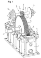
- a part of a compressor system is shown in perspective.
- a main gear wheel 5 is rotatably connected to a transmission input shaft 3.
- the main gear 5 drives a plurality of pinions 7 likewise mounted in the compressor housing 1.
- the output shafts 9, which are connected in a rotationally fixed manner to the pinions 7, extend through bearing openings 11 of the housing 1 beyond the housing walls and, as shown on the uppermost pinion shaft 9, can have runners at both ends Wear 13 of compressors.
- the pinion driving the output shaft 9 located at the top in FIG. 1 is the sun gear of a planetary gear 15, the ring gear 17 of which has external teeth and meshes with the main gear 5 designed as a central gear to drive the output shaft 9.
- the planetary gear 15 is together with a part of the main gear 5 and the gear housing 1 in Section shown.
- the output shaft 9 is rotatably connected to a sun gear 19 and extends through the bearing opening 11 of the housing 1 to the outside.
- the sun gear 19 meshes with planet gears which are rotatably mounted in the planet gear carrier 23 which is fixed relative to the housing 1.
- the planet gear 21 transmits the rotation of the ring gear 17 driven by the main gear 5 to the sun gear 19.
- the ring gear 17 is rotatably mounted on the non-rotatable planet gear carrier 23 by means of an angular contact ball bearing 25.
- the ring gear 17 has an oblique external toothing 27 for engagement with the helical toothing of the main gear 5 and on its inner circumference an internal toothing 29 which meshes with the planet gear 21, in this case straight.
- the planetary gear 15 shown in this example has a transmission ratio between the speed of the main gear 5 and the speed of the output shaft 9 of 23.5.
- the friction losses occurring in an oil film plain bearing 31 supporting the shaft 9 can be kept relatively low because of the rotational speed thereof proportional to the diameter of the output shaft 9.
- a resulting compressor axial thrust originating from the compressor rotors 13 on the output shaft 9 is transmitted to the planet gears 21 via pressure combs 33 fixedly attached to the output shaft 9. Because of the axial force transmitting formed by a deep groove ball bearing 35 Bearing arrangement this axial compressor thrust is transmitted to the planet gear carrier 23 and thus ultimately to the gear housing 1 which is fixedly connected to the planet gear carrier 23.
- the output shaft bearing unit 37 has an outer bearing part 39 which establishes the fixed connection between the transmission housing 1 and the planet gear carrier 23.
- the axial width of the toothing inside the planetary gear 15 can be smaller than the axial width of the main gear 5.
- the planetary gear 15 can be axially particularly compact and thus be installed in housings with a relatively small width. Such relatively narrow housings are particularly advantageous with regard to bending vibrations of the shafts mounted in the housing walls.
- the ring gear 17 is mounted on a support neck 43 of the planet gear carrier 23 via an angular contact ball bearing 25 via a ring gear bearing flange 41 which projects axially only slightly beyond the central wheel and extends radially onto the sun gear shaft 9.
- a ring gear bearing flange 41 which projects axially only slightly beyond the central wheel and extends radially onto the sun gear shaft 9.
- the ring gear carrier flange 41 between a support ring 45 of the outer bearing part 39 and a planet gear carrier flange 47 carrying the planet gears 21, which is arranged within the axial width of the main gear 5.
- the support neck 43 of the planet gear carrier 23 is fastened to the support ring 45 of the output shaft bearing unit 37 by means of screws 44, and the support ring 45 is fastened to the housing 1 by screws 46.
- the outer bearing part 39 of the output shaft bearing unit 37 and the planet gear carrier 23 as well as the ring gear carrier flange 41 can be produced by die casting, which proves to be particularly favorable in view of complicated shapes, oil supply channels etc.
- three planet gears 21 are preferably arranged uniformly in the circumferential direction around the sun gear shaft 9, so that the radial forces transmitted to the sun gear shaft 9 via the planet gears 21 largely compensate.
- These planet gears 21 can be made of plastic.
- the compressor system according to the invention thus offers very high ratios with a compact design and thus enables very high outlet pressures of a medium compressed in this system.
Landscapes
- Engineering & Computer Science (AREA)
- General Engineering & Computer Science (AREA)
- Mechanical Engineering (AREA)
- Retarders (AREA)
- Gear Transmission (AREA)
Claims (21)
- Système à compresseur comportant un engrenage monté dans la chaîne cinématique entre une unité d'entraînement et une zone de compresseur du système,
cet engrenage comportant un carter d'engrenage (1), un arbre d'entrée d'engrenage (3) monté dans ce carter d'engrenage (1), une roue dentée principale (5) voisine de l'entrée et au moins un arbre de sortie (9) entraîné par cette roue dentée principale (5), par l'intermédiaire d'un pignon (7, 19), menant à la zone de compresseur, avec un axe,
caractériséen ce que le pignon entraînant l'arbre de sortie (9) est formé par la roue planétaire (19) d'un engrenage planétaire (15) ;dans lequel un porte-satellites (23) de cet engrenage planétaire (15) est fixé sur le carter d'engrenage (1) ;dans lequel en outre une couronne (17) de cet engrenage planétaire (15) est montée tournante sur un élément de palier (43) fixe par rapport au carter d'engrenage (1) ;dans lequel en outre cette couronne (17) comporte une denture extérieure (27) en engagement avec la roue dentée principale (5) voisine de l'entrée ;dans lequel en outre au moins une roue satellite (21) est montée sur le porte-satellites (23) et est en engrènement avec une denture intérieure (29) de la couronne (17) ainsi qu'avec une denture extérieure de la roue planétaire (19) ;dans lequel en outre la roue planétaire ou/et l'arbre de sortie (9) est fixé axialement par au moins un peigne de pression (33) dans la direction axiale, sur ladite au moins une roue satellite (21) etdans lequel cette au moins une roue satellite (21) est soutenue axialement contre le porte-satellites (23), par un dispositif à palier (35) transmettant les forces axiales. - Système à compresseur selon la revendication 1,
caractérisé en ce que ledit au moins un peigne de pression (33) agit sur ladite au moins une roue satellite (21), à proximité radiale du cercle partiel de denture de la roue satellite (21). - Système à compresseur selon la revendication 1 ou 2,
caractérisé
en ce que l'arbre de sortie (9) est monté par une unité de palier d'arbre de sortie (37) dans une ouverture de palier (11) d'une paroi latérale du carter d'engrenage (1), cette unité de palier d'arbre de sortie (37) comportant un élément extérieur de palier (39) fixé dans la direction axiale et dans la direction périphérique sur le carter d'engrenage (1). - Système à compresseur selon la revendication 3,
caractérisé
en ce que l'ouverture de palier (11) est surdinensionnée par rapport au diamètre de l'arbre de sortie (9), le surdimensionnement étant compensé par un dimensionnement correspondant de l'unité de palier d'arbre de sortie (37). - Système à compresseur selon l'une des revendications 3 et 4, caractérisé
en ce que l'unité de palier d'arbre de sortie (37) est réalisée en palier glissant (31), en particulier avec un film d'huile d'appui. - Système à compresseur selon l'une des revendications 3 à 5, caractérisé en ce que le porte-satellites (23) est fixé sur l'élément extérieur de palier (39) de l'unité de palier d'arbre de sortie (37).
- Système à compresseur selon la revendication 6,
caractérisé en ce que la couronne (17) est montée sur le porte-satellite (23). - Système à compresseur selon la revendication 7,
caractérisé
en ce que la denture extérieure (27) de la couronne (17) est configurée en denture hélicoïdale et en ce que la couronne (17) est montée sur au moins l'une de ses extrémités axiales, sur le porte-satellites (23), par un roulement à billes transmettant les forces axiales, en particulier un roulement à billes à contact oblique (25). - Système à compresseur selon l'une des revendications 1 à 8 caractérisé
en ce que ladite au moins une roue satellite (21) au moins est montée sur le porte-satellites (23) par au moins un palier transmettant les forces axiales, en particulier un roulement rainuré à billes (35). - Système à compresseur selon l'une des revendications 3 à 9, caractérisé
en ce que l'élément extérieur de palier (39) de l'unité de palier d'arbre de sortie (37) est réalisé avec une bague d'appui (45) s'appliquant dans la zone périphérique de l'ouverture de palier (11), contre le côté intérieur de la paroi de carter, en ce que sur cette bague d'appui (45) est fixé, dans une zone radialement intérieure de celle-ci, un collet de support (43) du porte-satellites (23), en ce que ce collet de support (43) du porte-satellites (23) présente, à une extrémité proche de la roue satellite, une bride de support de couronne (47), dirigée radialement vers l'extérieur et en ce qu'une bride de support de couronne (41), dirigée radialement vers l'intérieur, est montée en direction axiale, entre la bride de support de roue satellite (47) et la bague d'appui (45), sur le collet de support (43) du porte-satellites (23). - Système à compresseur selon l'une des revendications 1 à 8, caractérisé
en ce que la couronne (17) est formée par une bague extérieure, présentant une denture extérieure (27) et une denture intérieure (29), et par une bride de support de couronne (41) fixée amovible sur cette bague extérieure, la bride de support de couronne (41) étant fixée sur au moins une extrémité axiale de la bague extérieure. - Système à compresseur selon l'une des revendications 1 à 11, caractérisé
en ce que la roue planétaire (19) et ladite au moins une roue satellite (21) sont réalisées avec des dentures droites. - Système à compresseur selon l'une des revendications 1 à 12, caractérisé
en ce que ladite au moins une roue satellite (21) est réalisée en matière plastique. - Système à compresseur selon l'une des revendications 1 à 13, caractérisé
en ce que la denture intérieure (29) de la couronne (17) présente une largeur axiale, qui est inférieure à la largeur axiale de la roue dentée principale (5) et en ce qu'une partie au moins de la largeur axiale du porte-satellites (23), est logée en recouvrement axial avec la largeur axiale de la roue dentée principale (5). - Système à compresseur selon l'une des revendications 1 à 14, caractérisé
en ce que l'engrenage planétaire (15) et ses paliers sont logés sensiblement symétriquement par rapport à un plan de symétrie orthogonal à l'axe d'arbre de sortie, entre deux parois du carter d'engrenage (1). - Système à compresseur selon l'une des revendications 1 à 15, caractérisé
en ce que l'arbre de sortie (9) traverse deux parois opposées l'une à l'autre du carter d'engrenage. - Système à compresseur selon l'une des revendications 1 à 16, caractérisé
en ce que l'arbre de sortie (9) porte, à au moins une extrémité, le rotor (13) d'un compresseur, en particulier d'un turbo-compresseur ou d'un compresseur à vis. - Système à compresseur selon l'une des revendications 1 à 17, caractérisé
en ce qu'une paire d'unités de compresseur (13) est reliée aux deux extrémités d'un arbre de sortie (9), de manière que les poussées axiales, transmises depuis ces unités de compresseur (13) à l'arbre de sortie (9), se compensent au moins partiellement. - Système à compresseur selon l'une des revendications 1 à 18,
caractérisé
en ce que la roue dentée principale (5) est placée en tant qu'une roue centrale dans le carter d'engrenage (1) et en ce que des emplacements de palier (11) pour une pluralité d'arbres de sortie (9), sont répartis autour de l'axe de la roue centrale (5), dans le carter d'engrenage (1). - Système à compresseur selon la revendication 19,
caractérisé
en ce que dans au moins l'un des emplacements de palier (11) est monté un arbre de sortie (9) avec pignon (7) correspondant, qui est en engrènement direct avec la roue dentée principale (5). - Système à compresseur selon l'une des revendications 1 à 20, caractérisé
en ce que la roue dentée principale (5) est solidaire en rotation de l'arbre d'entrée (3).
Applications Claiming Priority (2)
| Application Number | Priority Date | Filing Date | Title |
|---|---|---|---|
| DE4241141 | 1992-12-07 | ||
| DE4241141A DE4241141A1 (de) | 1992-12-07 | 1992-12-07 | Verdichteranlage mit einem im Antriebsstrang zwischen einer Antriebseinheit und einem Verdichterbereich der Anlage eingeschalteten Zahnradgetriebe |
Publications (2)
| Publication Number | Publication Date |
|---|---|
| EP0602491A1 EP0602491A1 (fr) | 1994-06-22 |
| EP0602491B1 true EP0602491B1 (fr) | 1996-10-09 |
Family
ID=6474585
Family Applications (1)
| Application Number | Title | Priority Date | Filing Date |
|---|---|---|---|
| EP93119606A Expired - Lifetime EP0602491B1 (fr) | 1992-12-07 | 1993-12-06 | Installation de transmission et de compression |
Country Status (3)
| Country | Link |
|---|---|
| US (1) | US5382132A (fr) |
| EP (1) | EP0602491B1 (fr) |
| DE (2) | DE4241141A1 (fr) |
Cited By (1)
| Publication number | Priority date | Publication date | Assignee | Title |
|---|---|---|---|---|
| DE102013208564A1 (de) | 2013-05-08 | 2014-11-13 | Voith Patent Gmbh | Getriebe und Getriebeverdichteranlage |
Families Citing this family (41)
| Publication number | Priority date | Publication date | Assignee | Title |
|---|---|---|---|---|
| US5402631A (en) * | 1991-05-10 | 1995-04-04 | Praxair Technology, Inc. | Integration of combustor-turbine units and integral-gear pressure processors |
| DE4234739C1 (de) * | 1992-10-15 | 1993-11-25 | Gutehoffnungshuette Man | Getriebe-Mehrwellenturbokompressor mit Rückführstufen |
| DE4436710C2 (de) * | 1994-10-14 | 1997-04-03 | Gutehoffnungshuette Man | Getriebe-Mehrwellenturbomaschine |
| JPH09119378A (ja) * | 1995-10-25 | 1997-05-06 | Ishikawajima Harima Heavy Ind Co Ltd | ターボ圧縮機 |
| ES2177162T3 (es) * | 1998-03-26 | 2002-12-01 | Uhde Gmbh | Procedimiento e instalacion para la preparacion de acido nitrico. |
| US6692234B2 (en) | 1999-03-22 | 2004-02-17 | Water Management Systems | Pump system with vacuum source |
| DE10003018B4 (de) * | 2000-01-25 | 2009-09-24 | Atlas Copco Energas Gmbh | Turboverdichter |
| GB2371339B (en) * | 2001-01-19 | 2003-05-07 | Visteon Global Tech Inc | Multi-speed gear arrangement for a centrifugal engine charger |
| SE519200C2 (sv) * | 2001-06-05 | 2003-01-28 | Volvo Aero Corp | Gasturbinanordning med ett arrangemang för drivning av en eller flera hjälpapparater |
| US7189068B2 (en) | 2003-09-19 | 2007-03-13 | Gast Manufacturing, Inc. | Sound reduced rotary vane compressor |
| DE102005002702A1 (de) * | 2005-01-19 | 2006-07-27 | Man Turbo Ag | Mehrstufiger Turbokompressor |
| US8342829B2 (en) * | 2005-12-08 | 2013-01-01 | Ghh Rand Schraubenkompressoren Gmbh | Three-stage screw compressor |
| EP1979618B1 (fr) | 2005-12-08 | 2016-04-27 | GHH-RAND Schraubenkompressoren GmbH | Groupe de compresseurs à vis à plusieurs étages |
| KR100873043B1 (ko) * | 2007-03-30 | 2008-12-09 | 삼성테크윈 주식회사 | 기어 케이스 어셈블리 |
| DE102008031116B4 (de) | 2008-05-29 | 2022-02-03 | Man Energy Solutions Se | Getriebeturbomaschine für einen Maschinenstrang, Maschinenstrang mit und Getriebe für Getriebeturbomaschine |
| DE102008038787A1 (de) * | 2008-08-13 | 2010-02-18 | Siemens Aktiengesellschaft | Fluidenergiemaschine |
| US8998586B2 (en) * | 2009-08-24 | 2015-04-07 | David Muhs | Self priming pump assembly with a direct drive vacuum pump |
| IT1398142B1 (it) * | 2010-02-17 | 2013-02-14 | Nuovo Pignone Spa | Sistema singolo con compressore e pompa integrati e metodo. |
| KR101009742B1 (ko) * | 2010-10-29 | 2011-01-19 | 주식회사 세진아이지비 | 동력전달장치 |
| DE102011003525A1 (de) * | 2011-02-02 | 2012-08-02 | Siemens Aktiengesellschaft | Gestufte Teilfuge an einem Getriebegehäuse |
| JP5863320B2 (ja) | 2011-08-05 | 2016-02-16 | 三菱重工コンプレッサ株式会社 | 遠心圧縮機 |
| DE102012018468B4 (de) * | 2012-09-19 | 2022-07-14 | Man Energy Solutions Se | Getriebeturbomaschine |
| DE102012217441A1 (de) * | 2012-09-26 | 2014-03-27 | Siemens Aktiengesellschaft | Getriebeverdichter |
| US9017046B2 (en) * | 2013-01-02 | 2015-04-28 | Elijah Anim Owusu | Fan assembly having multiple centrifugal fans in mechanical connection with a planetary gear system |
| DE102013210497A1 (de) | 2013-06-06 | 2014-12-11 | Siemens Aktiengesellschaft | Getriebeverdichter |
| US10145381B2 (en) * | 2014-01-23 | 2018-12-04 | Mitsubishi Heavy Industries Compressor Corporation | Geared centrifugal compressor with pressure adjustment portion to balance axial thrust |
| US20150211539A1 (en) | 2014-01-24 | 2015-07-30 | Air Products And Chemicals, Inc. | Systems and methods for compressing air |
| CN104005966A (zh) * | 2014-05-29 | 2014-08-27 | 安徽银龙泵阀股份有限公司 | 一种利用星级齿轮原理旋转的多转轴泵芯 |
| EP3159547B1 (fr) * | 2014-09-18 | 2019-06-19 | Mitsubishi Heavy Industries Compressor Corporation | Système de compression |
| DE102014219137A1 (de) * | 2014-09-23 | 2016-03-24 | Siemens Aktiengesellschaft | Dichtelement für gestufte Teilfugen an Getriebegehäusen |
| DE102014221339A1 (de) * | 2014-10-21 | 2016-04-21 | Siemens Aktiengesellschaft | Gestufte Teilfuge an einem Getriebegehäuse |
| EP3221590B1 (fr) | 2014-11-21 | 2018-10-17 | Voith Patent GmbH | Réducteur et turbomachine à réducteur |
| EP3234409A1 (fr) * | 2014-12-19 | 2017-10-25 | Voith Patent GmbH | Boîtier pour transmission, notamment transmission intégrale |
| JP6395683B2 (ja) * | 2015-09-02 | 2018-09-26 | 株式会社神戸製鋼所 | 圧縮機 |
| DE102017103696A1 (de) | 2017-02-23 | 2018-08-23 | Voith Patent Gmbh | Antriebsvorrichtung mit Überlagerungsgetriebe |
| DE102017103695A1 (de) | 2017-02-23 | 2018-08-23 | Voith Patent Gmbh | Antriebsvorrichtung mit Überlagerungsgetriebe |
| WO2018019613A1 (fr) | 2016-07-26 | 2018-02-01 | Voith Patent Gmbh | Dispositif d'entraînement muni d'un engrenage de superposition |
| CN109372776A (zh) * | 2018-11-26 | 2019-02-22 | 黄莲英 | 一种排气面积大的室内换气扇 |
| CN109779920B (zh) * | 2019-03-11 | 2020-12-08 | 衢州学院 | 一种基于行星轮系的两级增速旋涡泵装置 |
| DE102021120100A1 (de) | 2021-08-03 | 2023-02-09 | Voith Patent Gmbh | Stirnradgetriebe |
| JP2023123909A (ja) * | 2022-02-25 | 2023-09-06 | 三菱重工コンプレッサ株式会社 | ギアド圧縮機 |
Family Cites Families (15)
| Publication number | Priority date | Publication date | Assignee | Title |
|---|---|---|---|---|
| DE7323092U (de) * | 1974-03-07 | Bhs Ag | Verdichtergetriebe | |
| US1435821A (en) * | 1920-11-29 | 1922-11-14 | North East Electric Co | Epicycloidal gearing |
| US2403381A (en) * | 1944-07-19 | 1946-07-02 | Bendix Aviat Corp | Regulated system |
| US3001692A (en) * | 1949-07-26 | 1961-09-26 | Schierl Otto | Multistage compressors |
| DE1095700B (de) * | 1958-06-06 | 1960-12-22 | Iaweseria Ag | Schiffsgetriebe |
| FR1205150A (fr) * | 1958-07-03 | 1960-01-29 | Amplificateur de puissance par transmissions combinées et en particulier pour automobiles | |
| GB1000877A (en) * | 1962-06-30 | 1965-08-11 | Ckd Praha | Improvements in or relating to rotary blowers or compressors |
| DE2113594A1 (de) * | 1971-03-20 | 1972-10-12 | Gutehoffnungshuette Sterkrade | Stirnradueberlagerungsgetriebe |
| DE2256681B2 (de) * | 1972-11-18 | 1976-05-26 | Demag Ag, 4100 Duisburg | Getriebegehaeuse fuer turboverdichter |
| FR2234490A1 (en) * | 1973-06-20 | 1975-01-17 | Bhs Bayerische Berg | Compressor drive gear with central wheel - has pinion shafts equipped with thrust rings |
| DD158489A3 (de) * | 1981-02-25 | 1983-01-19 | Helmut Paulat | Getriebe,insbesondere fuer mehrwellenverdichter |
| JPH01267397A (ja) * | 1988-04-15 | 1989-10-25 | Hitachi Ltd | 遠心圧縮機 |
| DE4003482A1 (de) * | 1990-02-06 | 1991-08-08 | Borsig Babcock Ag | Getriebe-turboverdichter |
| DE4204338C2 (de) * | 1992-02-11 | 1993-11-18 | Mannesmann Ag | Getriebe-Turboverdichter |
| DE9201858U1 (de) * | 1992-02-11 | 1992-04-02 | Mannesmann AG, 4000 Düsseldorf | Getriebe-Turboverdichter |
-
1992
- 1992-12-07 DE DE4241141A patent/DE4241141A1/de not_active Ceased
-
1993
- 1993-11-10 US US08/150,695 patent/US5382132A/en not_active Expired - Lifetime
- 1993-12-06 DE DE59304119T patent/DE59304119D1/de not_active Expired - Fee Related
- 1993-12-06 EP EP93119606A patent/EP0602491B1/fr not_active Expired - Lifetime
Cited By (1)
| Publication number | Priority date | Publication date | Assignee | Title |
|---|---|---|---|---|
| DE102013208564A1 (de) | 2013-05-08 | 2014-11-13 | Voith Patent Gmbh | Getriebe und Getriebeverdichteranlage |
Also Published As
| Publication number | Publication date |
|---|---|
| DE4241141A1 (de) | 1994-06-09 |
| DE59304119D1 (de) | 1996-11-14 |
| US5382132A (en) | 1995-01-17 |
| EP0602491A1 (fr) | 1994-06-22 |
Similar Documents
| Publication | Publication Date | Title |
|---|---|---|
| EP0602491B1 (fr) | Installation de transmission et de compression | |
| EP1110011B1 (fr) | Reducteur a plusieurs etages de pignons cylindriques | |
| EP1000280B1 (fr) | Systeme modulaire d'engrenage dote d'un engrenage a couronne dentee | |
| AT394757B (de) | Nebenantrieb einer brennkraftmaschine | |
| EP1098063B1 (fr) | Moteur tubulaire | |
| EP1252444B1 (fr) | Systeme d'entrainement de pompe a vis | |
| DE102016118877B4 (de) | Mechanische Getriebeanordnung | |
| EP3351826B1 (fr) | Boîte de transmission multi-étagée compacte comprenant un engrenage planétaire et une démultiplication harmonique s'y raccordant | |
| DE102019124666B4 (de) | Differenzialgetriebe | |
| EP1574316A1 (fr) | Transmission pour extrudeuse à deux vis | |
| EP0736692B1 (fr) | Etanchéité, aménagement des paliers et entraínement des rotors d'un compresseur à vis tournant à sec | |
| CH665893A5 (de) | Planetengetriebe, das zwischen einer stroemungsmaschine und einer elektrischen maschine in einem getriebegehaeuse angeordnet ist. | |
| EP2271858B1 (fr) | Transmission et système d'engrenage différentiel | |
| DE2403016A1 (de) | Getriebe fuer ein vortriebsgeblaese mit veraenderlicher blattsteigung | |
| DD141941A5 (de) | Innenachsige maschine mit schraubenfoermigem profil am rotor und im stator | |
| DE102004002052B4 (de) | Wellgetriebe | |
| EP3768994A1 (fr) | Engrenage planétaire pourvu d'un pignon planétaire à une dent ayant une denture évoloïde | |
| DE4204338C2 (de) | Getriebe-Turboverdichter | |
| EP1502792B1 (fr) | Unité d'entrainement pour chariot de manutention | |
| DE3941719A1 (de) | Umlaufgetriebe | |
| DD294763A5 (de) | Getriebe | |
| EP1067291B1 (fr) | Transmission et compresseur centrifuge | |
| EP0622544A1 (fr) | Dispositif de réglage des pales de pompe à écoulement axial | |
| EP0395980A1 (fr) | Dispositif de levage | |
| DE69324172T2 (de) | Getriebevorrichtung |
Legal Events
| Date | Code | Title | Description |
|---|---|---|---|
| PUAI | Public reference made under article 153(3) epc to a published international application that has entered the european phase |
Free format text: ORIGINAL CODE: 0009012 |
|
| AK | Designated contracting states |
Kind code of ref document: A1 Designated state(s): CH DE FR GB LI |
|
| 17P | Request for examination filed |
Effective date: 19940623 |
|
| 17Q | First examination report despatched |
Effective date: 19950619 |
|
| RAP1 | Party data changed (applicant data changed or rights of an application transferred) |
Owner name: BHS-BAYERISCHE BERG-, HUETTEN- UND SALZWERKE AKTIE |
|
| GRAH | Despatch of communication of intention to grant a patent |
Free format text: ORIGINAL CODE: EPIDOS IGRA |
|
| GRAA | (expected) grant |
Free format text: ORIGINAL CODE: 0009210 |
|
| RAP1 | Party data changed (applicant data changed or rights of an application transferred) |
Owner name: BHS-CINCINNATI GETRIEBETECHNIK GMBH |
|
| AK | Designated contracting states |
Kind code of ref document: B1 Designated state(s): CH DE FR GB LI |
|
| REG | Reference to a national code |
Ref country code: CH Ref legal event code: NV Representative=s name: E. BLUM & CO. PATENTANWAELTE |
|
| GBT | Gb: translation of ep patent filed (gb section 77(6)(a)/1977) |
Effective date: 19961010 |
|
| REF | Corresponds to: |
Ref document number: 59304119 Country of ref document: DE Date of ref document: 19961114 |
|
| ET | Fr: translation filed | ||
| PLBI | Opposition filed |
Free format text: ORIGINAL CODE: 0009260 |
|
| PLBQ | Unpublished change to opponent data |
Free format text: ORIGINAL CODE: EPIDOS OPPO |
|
| PLBF | Reply of patent proprietor to notice(s) of opposition |
Free format text: ORIGINAL CODE: EPIDOS OBSO |
|
| 26 | Opposition filed |
Opponent name: RENK AKTIENGESELLSCHAFT Effective date: 19970630 |
|
| PLBF | Reply of patent proprietor to notice(s) of opposition |
Free format text: ORIGINAL CODE: EPIDOS OBSO |
|
| PLBQ | Unpublished change to opponent data |
Free format text: ORIGINAL CODE: EPIDOS OPPO |
|
| PLAB | Opposition data, opponent's data or that of the opponent's representative modified |
Free format text: ORIGINAL CODE: 0009299OPPO |
|
| R26 | Opposition filed (corrected) |
Opponent name: RENK AKTIENGESELLSCHAFT Effective date: 19970630 |
|
| PLBO | Opposition rejected |
Free format text: ORIGINAL CODE: EPIDOS REJO |
|
| PLBN | Opposition rejected |
Free format text: ORIGINAL CODE: 0009273 |
|
| STAA | Information on the status of an ep patent application or granted ep patent |
Free format text: STATUS: OPPOSITION REJECTED |
|
| 27O | Opposition rejected |
Effective date: 19981017 |
|
| PGFP | Annual fee paid to national office [announced via postgrant information from national office to epo] |
Ref country code: FR Payment date: 19991015 Year of fee payment: 7 Ref country code: DE Payment date: 19991015 Year of fee payment: 7 |
|
| PGFP | Annual fee paid to national office [announced via postgrant information from national office to epo] |
Ref country code: CH Payment date: 19991109 Year of fee payment: 7 |
|
| PGFP | Annual fee paid to national office [announced via postgrant information from national office to epo] |
Ref country code: GB Payment date: 19991201 Year of fee payment: 7 |
|
| PG25 | Lapsed in a contracting state [announced via postgrant information from national office to epo] |
Ref country code: GB Free format text: LAPSE BECAUSE OF NON-PAYMENT OF DUE FEES Effective date: 20001206 |
|
| PG25 | Lapsed in a contracting state [announced via postgrant information from national office to epo] |
Ref country code: LI Free format text: LAPSE BECAUSE OF NON-PAYMENT OF DUE FEES Effective date: 20001231 Ref country code: CH Free format text: LAPSE BECAUSE OF NON-PAYMENT OF DUE FEES Effective date: 20001231 |
|
| GBPC | Gb: european patent ceased through non-payment of renewal fee |
Effective date: 20001206 |
|
| REG | Reference to a national code |
Ref country code: CH Ref legal event code: PL |
|
| PG25 | Lapsed in a contracting state [announced via postgrant information from national office to epo] |
Ref country code: FR Free format text: LAPSE BECAUSE OF NON-PAYMENT OF DUE FEES Effective date: 20010831 |
|
| REG | Reference to a national code |
Ref country code: FR Ref legal event code: ST |
|
| PG25 | Lapsed in a contracting state [announced via postgrant information from national office to epo] |
Ref country code: DE Free format text: LAPSE BECAUSE OF NON-PAYMENT OF DUE FEES Effective date: 20011002 |