EP0602491B1 - Transmission and compressor system - Google Patents
Transmission and compressor system Download PDFInfo
- Publication number
- EP0602491B1 EP0602491B1 EP93119606A EP93119606A EP0602491B1 EP 0602491 B1 EP0602491 B1 EP 0602491B1 EP 93119606 A EP93119606 A EP 93119606A EP 93119606 A EP93119606 A EP 93119606A EP 0602491 B1 EP0602491 B1 EP 0602491B1
- Authority
- EP
- European Patent Office
- Prior art keywords
- gear
- output shaft
- compressor system
- planet
- bearing
- Prior art date
- Legal status (The legal status is an assumption and is not a legal conclusion. Google has not performed a legal analysis and makes no representation as to the accuracy of the status listed.)
- Expired - Lifetime
Links
- 230000005540 biological transmission Effects 0.000 title claims description 27
- 230000002093 peripheral effect Effects 0.000 claims description 3
- 230000000284 resting effect Effects 0.000 claims 1
- 229920002994 synthetic fiber Polymers 0.000 claims 1
- 210000001520 comb Anatomy 0.000 description 5
- 230000002349 favourable effect Effects 0.000 description 4
- 238000013461 design Methods 0.000 description 3
- 238000000034 method Methods 0.000 description 3
- 238000005452 bending Methods 0.000 description 2
- 238000009434 installation Methods 0.000 description 2
- 238000004519 manufacturing process Methods 0.000 description 2
- 238000012545 processing Methods 0.000 description 2
- 230000000717 retained effect Effects 0.000 description 2
- 239000000126 substance Substances 0.000 description 2
- 235000013361 beverage Nutrition 0.000 description 1
- 238000002485 combustion reaction Methods 0.000 description 1
- 238000005056 compaction Methods 0.000 description 1
- 230000006835 compression Effects 0.000 description 1
- 238000007906 compression Methods 0.000 description 1
- 238000010276 construction Methods 0.000 description 1
- 238000011161 development Methods 0.000 description 1
- 238000004512 die casting Methods 0.000 description 1
- 238000005553 drilling Methods 0.000 description 1
- 230000000694 effects Effects 0.000 description 1
- 239000003351 stiffener Substances 0.000 description 1
- 238000012546 transfer Methods 0.000 description 1
- 238000013519 translation Methods 0.000 description 1
- 238000011144 upstream manufacturing Methods 0.000 description 1
Images

Classifications
-
- F—MECHANICAL ENGINEERING; LIGHTING; HEATING; WEAPONS; BLASTING
- F04—POSITIVE - DISPLACEMENT MACHINES FOR LIQUIDS; PUMPS FOR LIQUIDS OR ELASTIC FLUIDS
- F04D—NON-POSITIVE-DISPLACEMENT PUMPS
- F04D25/00—Pumping installations or systems
- F04D25/02—Units comprising pumps and their driving means
- F04D25/028—Units comprising pumps and their driving means the driving means being a planetary gear
-
- F—MECHANICAL ENGINEERING; LIGHTING; HEATING; WEAPONS; BLASTING
- F04—POSITIVE - DISPLACEMENT MACHINES FOR LIQUIDS; PUMPS FOR LIQUIDS OR ELASTIC FLUIDS
- F04D—NON-POSITIVE-DISPLACEMENT PUMPS
- F04D25/00—Pumping installations or systems
- F04D25/16—Combinations of two or more pumps ; Producing two or more separate gas flows
- F04D25/163—Combinations of two or more pumps ; Producing two or more separate gas flows driven by a common gearing arrangement
-
- F—MECHANICAL ENGINEERING; LIGHTING; HEATING; WEAPONS; BLASTING
- F16—ENGINEERING ELEMENTS AND UNITS; GENERAL MEASURES FOR PRODUCING AND MAINTAINING EFFECTIVE FUNCTIONING OF MACHINES OR INSTALLATIONS; THERMAL INSULATION IN GENERAL
- F16H—GEARING
- F16H1/00—Toothed gearings for conveying rotary motion
- F16H1/28—Toothed gearings for conveying rotary motion with gears having orbital motion
Landscapes
- Engineering & Computer Science (AREA)
- General Engineering & Computer Science (AREA)
- Mechanical Engineering (AREA)
- Retarders (AREA)
- Gear Transmission (AREA)
Description
Die Erfindung betrifft eine Verdichteranlage mit einem im Antriebsstrang zwischen einer Antriebseinheit und einem Verdichterbereich der Anlage eingeschalteten Zahnradgetriebe, dieses Zahnradgetriebe umfassend ein Getriebegehäuse, in diesem Getriebegehäuse gelagert eine Getriebeeingangswelle, ein eingangsnahes Hauptzahnrad und wenigstens eine von diesem Hauptzahnrad her über ein Ritzel angetriebene zum Verdichterbereich führende Ausgangswelle mit einer Achse.The invention relates to a compressor system with a gear transmission switched on in the drive train between a drive unit and a compressor area of the system, this gear transmission comprising a gear housing, in this gear housing a gear input shaft, a main gear close to the input and at least one gear driven from this main gear via a pinion leading to the compressor area Output shaft with one axis.
Von einer solchen Getriebe-Turboverdichteranlage wird in neuester Zeit die Erreichung von Druckverhältnissen von pA/pE = 60 und mehr gefordert, wobei pE den Druck im Verdichtereingang und pA den Druck im Verdichterausgang bedeuten. Voraussetzung hierfür sind die Übertragung großer Momente bei mittleren Drehzahlen für die auf geringem Druckniveau verdichtenden Verdichterstufen und höchste Drehzahlen für die auf höherem Druckniveau verdichtenden Verdichterstufen. Diese höchsten Drehzahlen lassen sich mit einstufigen Getrieben allein nicht mehr erzielen. Es müssen also in einigen Stufen die Verdichtereinheiten durch ein einstufiges und in anderen Verdichterstufen die Verdichtereinheiten durch ein zweistufiges Getriebe angetrieben werden.Such a gearbox turbocompressor system has recently been required to achieve pressure ratios of p A / p E = 60 and more, p E meaning the pressure in the compressor inlet and p A the pressure in the compressor outlet. The prerequisites for this are the transmission of high torques at medium speeds for the compressor stages compressing at a low pressure level and highest speeds for the compressor stages compressing at a higher pressure level. These highest speeds can no longer be achieved with single-stage gearboxes alone. So in some stages the compressor units have to be driven by a single stage and in other compressor stages the compressor units have to be driven by a two stage gear.
Ein Getriebe der eingangs bezeichneten Bauart ist aus der deutschen Patentschrift DE-C2 40 03 482 bekannt. Bei dieser bekannten Ausführungsform ist zum Antrieb einer mit hoher Drehzahl angetriebenen Verdichtereinheit ein zweistufiges Zwischenrad vorgesehen, welches mit einem Zahnring kleineren Durchmessers in Eingriff mit dem Hauptzahnrad steht und mit einem Zahnring größeren Durchmessers in Eingriff mit einem Ritzel einer Ausgangswelle steht.A transmission of the type described above is known from German patent DE-C2 40 03 482. In this known embodiment, a two-stage intermediate wheel is provided for driving a high-speed compressor unit, which meshes with a toothed ring of smaller diameter Main gear stands and with a larger diameter gear ring is in engagement with a pinion of an output shaft.
Eine weitere Vorrichtung eingangs bezeichneter Art ist aus der DE U 92 01 858 bekannt. Dabei kämmt mit dem eingangsnahen Hauptzahnrad ein Trippel-Zahnrad und zwar mit seinem axial mittleren Zahnring geringerer Zähnezahl, während die beiden axial endständigen Zahnringe von jeweils größerer Zähnezahl mit je einem Ritzel einer Ausgangswelle in Eingriff stehen.Another device of the type described in the opening paragraph is known from DE U 92 01 858. A triple gear meshes with the main gear close to the input, specifically with its axially central toothed ring with a smaller number of teeth, while the two axially terminal toothed rings, each with a larger number of teeth, engage with a pinion of an output shaft.
Wenn bei den bekannten Lösungen an der Ausgangswelle von einer Verdichtereinheit oder auch von zwei an den beiden Enden der Ausgangswelle angebrachten Verdichtereinheiten ein resultierender Schub auf die Ausgangswelle ausgeübt wird, so kann man diesen resultierenden Schub durch Druckkämme auf den mit dem Ritzel kämmenden Zahnkranz übertragen. Dies ist eine an sich vorteilhafte Lösung, weil an der Übertragungsstelle zwischen den Druckkämmen und einem verzahnungsnahen Anlagebereich des Zahnkranzes relativ geringe Relativbewegungen auftreten, so daß dort verhältnismäßig geringe Reibungsverluste zu erwarten sind im Vergleich zu Reibungsverlusten, die man erwarten müßte, wenn man die Ausgangswelle durch axialschubübertragende Lagerungen lagern wollte. So vorteilhaft diese Lösung aus dem vorstehend angegebenen Gründen sein mag, so verbleibt doch ein gewisses Problem insofern, als resultierender axialer Schub, der durch einen Druckkamm auf einen dem Ritzel vorgeschalteten Zahnkranz übertragen wird, zu einem Kippmoment auf den diesem Zahnkranz zugehörigen Radkörper führt, der zu schwer kontrollierbaren Fehlstellungen Anlaß geben kann.If, in the known solutions, a resultant thrust is exerted on the output shaft by a compressor unit or also by two compressor units attached to the two ends of the output shaft, this resultant thrust can be transmitted by pressure combs to the ring gear meshing with the pinion. This is an advantageous solution in itself because relatively small relative movements occur at the transfer point between the pressure combs and a toothed contact area of the ring gear, so that relatively low friction losses are to be expected there compared to friction losses that one would have to expect if one were to pass the output shaft through wanted to store axial thrust-transmitting bearings. As advantageous as this solution may be for the reasons given above, there remains a certain problem insofar as the resulting axial thrust, which is transmitted by a pressure comb to a ring gear upstream of the pinion, leads to a tilting moment on the wheel body associated with this ring gear, which can give rise to malpositions that are difficult to control.
Ein weiterer Nachteil der bekannten Lösung besteht darin, daß durch Doppel- oder Trippelräder die Gehäusebreite erhöht und damit die "Biegelänge" der mit Ritzel versehenen Ausgangswellen größer wird, was zu unkontrollierbaren Schwingungen führen kann.Another disadvantage of the known solution is that the housing width is increased by double or triple wheels and thus the "bending length" of the output shafts provided with pinions is larger, which can lead to uncontrollable vibrations.
Ein weiterer Nachteil der bekannten Lösungen ist es, daß das auf Kompaktheit und Steifigkeit auszulegende Gehäuse größer wird und deshalb weiterer Versteifungsmaßnahmen bedarf. Dieses Getriebegehäuse wird durch Zunahme der Größe und durch Anbringung von Versteifungsmitteln immer noch größer und schwieriger zu handhaben.Another disadvantage of the known solutions is that the housing, which is to be designed for compactness and rigidity, becomes larger and therefore requires further stiffening measures. This gearbox is becoming larger and more difficult to handle due to the increase in size and the application of stiffeners.
Der Erfindung liegt die Aufgabe zugrunde, unter Vermeidung der vorstehend zum Stand der Technik angegebenen Nachteile, eine Verdichteranlage der eingangs bezeichneten Art so auszubilden, daß Kippbelastungen auf Zahnräder reduziert werden und die Gehäusedimensionen möglichst gering gehalten werden können. Weiter soll die Möglichkeit erhalten bleiben, auf bekannte Gehäuseformen zurückgreifen zu können, die bei geringerem Drehzahlbedarf angewandt wurden und serienmäßig zur Verfügung stehen.The invention is based on the object, avoiding the disadvantages indicated above in relation to the prior art, of designing a compressor system of the type mentioned at the outset in such a way that tilting loads on gearwheels are reduced and the housing dimensions can be kept as small as possible. Furthermore, the possibility is to be retained of being able to fall back on known housing shapes which were used with a lower speed requirement and are available as standard.
Weiter soll die Möglichkeit erhalten bleiben, in ein und derselben Lagerstelle eines Getriebegehäuses wahlweise Wellen für mittlere Drehzahlen und höchste Drehzahlen einbauen zu können.Furthermore, the possibility should be retained of being able to install shafts for medium speeds and highest speeds in one and the same bearing point of a gearbox housing.
Zur Lösung dieser Aufgabe wird erfindungsgemäß vorgeschlagen, daß das die Ausgangswelle treibende Ritzel von dem Sonnenrad eines Planetengetriebes gebildet ist; wobei ein Planetenradträger dieses Planetengetriebes an dem Getriebegehäuse festgelegt ist; wobei weiter ein Hohlrad dieses Planetengetriebes an einem gegenüber dem Getriebegehäuse feststehenden Lagerteil drehbar gelagert ist; wobei weiter dieses Hohlrad eine Außenverzahnung im Eingriff mit dem eingangsnahen Hauptzahnrad aufweist; wobei weiter mindestens ein Planetenrad auf dem Planetenradträger gelagert ist und in Zahneingriff mit einer Innenverzahnung des Hohlrads sowie mit einer Außenverzahnung des Sonnenrads steht; wobei weiter das Sonnenrad oder/und die Ausgangswelle durch mindestens einen Druckkamm in axialer Richtung an dem mindestens einen Planetenrad axial festgelegt ist; und wobei dieses mindestens eine Planetenrad an dem Planetenradträger durch eine axialkraftübertragende Lageranordnung in axialer Richtung abgestützt ist.To solve this problem, the invention proposes that the pinion driving the output shaft is formed by the sun gear of a planetary gear; wherein a planet carrier of this planetary gear is fixed to the gear housing; wherein a ring gear of this planetary gear is rotatably mounted on a bearing part which is fixed relative to the gear housing; wherein this ring gear further has external teeth in engagement with the main gear near the input; wherein at least one planet gear is mounted on the planet gear carrier and is in meshing engagement with an internal toothing of the ring gear and with an external toothing of the sun gear; wherein the sun gear and / or the output shaft is axially fixed to the at least one planet gear by at least one pressure comb in the axial direction; and wherein this at least one planet gear is supported on the planet gear carrier by an axial force-transmitting bearing arrangement in the axial direction.
Bei der erfindungsgemäßen Lösung ergeben sich folgende Vorteile:The advantages of the solution according to the invention are as follows:
Es können wesentlich größere Drehzahlen erzielt werden. So kann beispielsweise zwischen der Drehzahl der Eingangswelle NE und der Drehzahl der Ausgangswelle NA problemlos ein Übersetzungsverhältnis iges. von 23,5 erzielt werden, was bei Annahme einer Drehzahl der Eingangswelle von 2.980 min-1 zu einer Drehzahl der Eingangswelle NA von 70.000 min-1 führt. Dabei kann der Achsabstand zwischen der Achse des Hauptzahnrads und der Achse der Ausgangswelle bei ca. 559 mm gehalten werden.Much higher speeds can be achieved. For example, between the speed of the input shaft N E and the speed of the output shaft N A, a gear ratio i total can be easily achieved . of 23.5 can be achieved, which, assuming a speed of the input shaft of 2,980 min -1 leads to a speed of the input shaft N A of 70,000 min -1 . The center distance between the axis of the main gear and the axis of the output shaft can be kept at approx. 559 mm.
Ein resultierender axialer Schub auf die Ausgangswelle wird durch einen oder vorzugsweise durch zwei Druckkämme auf ein oder mehrere vorzugsweise drei Planetenräder übertragen, die in gleichmäßigem Umfangsabstand um die Achse der Ausgangswelle angeordnet sind. Der Effekt geringer Reibung zwischen Druckkamm der Ausgangswelle und angrenzendem Anlagebereich des Planetenrads tritt auch hier ein. Zusätzlich tritt aber der Vorteil ein, daß verhältnismäßig geringe Kippmomente auf den Radkörper des Planetenrads übertragen werden, da dieses Planetenrad nur relativ geringen Radius besitzt. Von dem relativ langsamer laufenden Planetenrad kann der axiale Schub dann relativ einfach auf den Planetenradträger durch ein axialkraftübertragendes Lager, beispielsweise ein Rillen-Kugellager, übertragen werden. Dies wird um so unproblematischer je größer die Zahl der über den Umfang verteilt angeordneten Planetenräder ist. Hinzu kommt, daß die durch Schubkraftübertragung belastenden Lager der Planetenräder angepaßt an die Planetenradlagerzapfen relativ geringen Durchmesser besitzen, so daß damit die Umfangsgeschwindigkeiten in diesen Lagern relativ klein werden.A resulting axial thrust on the output shaft is transmitted by one or preferably by two pressure combs to one or more preferably three planet gears, which are arranged at a uniform circumferential distance around the axis of the output shaft. The effect of low friction between the pressure comb of the output shaft and the adjacent contact area of the planet gear also occurs here. In addition, there is the advantage that relatively low tilting moments on the wheel body of the Planet gear are transmitted because this planet gear has only a relatively small radius. The axial thrust can then be transferred relatively easily from the relatively slower-running planet gear to the planet gear carrier by an axial force-transmitting bearing, for example a grooved ball bearing. This becomes all the less problematic the greater the number of planet gears distributed over the circumference. In addition, the bearings of the planet gears, which are loaded by the transmission of thrust, are relatively small in diameter, so that the peripheral speeds in these bearings are relatively small.
In Weiterbildung der Erfindung wird vorgeschlagen, daß der mindestens eine Druckkamm an dem mindestens einen Planetenrad in radialer Nähe zu dem Verzahnungsteilkreis des Planetenrads angreift; durch diese Maßnahme wird, wie schon angedeutet, erreicht, daß geringstmögliche Relativgeschwindigkeiten an den Berührungsstellen zwischen Druckkamm und Planetenrad auftreten.In a development of the invention it is proposed that the at least one pressure comb acts on the at least one planet gear in radial proximity to the toothed pitch circle of the planet gear; As already indicated, this measure ensures that the lowest possible relative speeds occur at the points of contact between the pressure comb and the planet gear.
Nach einer bevorzugten Ausgestaltungsform der Erfindung ist vorgesehen, daß die Ausgangswelle durch eine Ausgangswellenlagereinheit in einer Lageröffnung einer Seitenwand des Getriebegehäuses gelagert ist, wobei diese Ausgangswellenlagereinheit einen am Getriebegehäuse in axialer Richtung und in Umfangsrichtung festgelegten Lageraußenteil umfaßt. Stellt man sich vor, daß ein Getriebegehäuse zur Verfügung steht, welches ursprünglich für direkten Eingriff des Ritzels mit einem Zentralrad gedacht war, so kann man also in einer Gehäusewand dieses Getriebegehäuses unter Verwendung des Bohrbilds das für die Lagerung einer solchen Ausgangswelle mit direkt in das Hauptrad eingreifendem Ritzel bestimmt war, eine Ausgangswellenlagereinheit vorsehen, an der alle Lagerfunktionen für das Planetengetriebe übernommen werden können. Eine neue Verbohrung des Getriebegehäuses erübrigt sich damit.According to a preferred embodiment of the invention, it is provided that the output shaft is supported by an output shaft bearing unit in a bearing opening of a side wall of the gear housing, this output shaft bearing unit comprising an outer bearing part fixed to the gear housing in the axial direction and in the circumferential direction. If you imagine that a gearbox is available, which was originally intended for direct engagement of the pinion with a central gear, you can use the drilling pattern in a housing wall of this gearbox to mount such an output shaft directly into the main gear engaging pinion was intended to provide an output shaft bearing unit on which all Bearing functions for the planetary gear can be taken over. This eliminates the need to drill the gearbox housing.
Geht man weiter davon aus, daß die Ausgangswelle bei Einbau des Planetengetriebes im Durchmesser kleiner wird als die Ausgangswelle bei direktem Eingriff ihres Ritzels mit dem Hauptzahnrad, so kann die Ausgangswellenlagereinheit die Durchmesseranpassung der schlankeren Ausgangswelle ohne weiteres übernehmen. Es ist hier noch anzumerken, daß die schlankere Gestaltung der Ausgangswelle bei Einschaltung des Planetengetriebes nicht nur baulich bedingt, sondern auch funktionsmäßig akzeptabel ist, denn durch die Zwischenschaltung des Planetengetriebes kann die Ausgangsdrehzahl erhöht werden und damit eine geforderte Leistung mit geringerem Ausgangswellenquerschnitt übertragen werden.If one assumes further that the diameter of the output shaft when the planetary gear is installed is smaller than the output shaft when its pinion engages directly with the main gear, the output shaft bearing unit can easily adapt the diameter of the slimmer output shaft. It should also be noted here that the slimmer design of the output shaft when the planetary gear is switched on is not only structurally necessary, but also functionally acceptable, since the intermediate speed can be increased by the interposition of the planetary gear and thus a required power with a smaller output shaft cross section can be transmitted.
Die Ausgangswellenlagereinheit wird bevorzugt als Gleitlager ausgeführt. Gleitlager sind im besonderem Maße geeignet, den sehr hohen Drehzahlen standzuhalten. Wie im Zusammenhang mit der Einführung des Lageraußenteils schon angedeutet, kann dieses Lageraußenteil auch Lagerfunktionen für das Planetengetriebe übernehmen, etwa in der Weise, daß der Planetenradträger an dem Lageraußenteil der Ausgangswellenlagereinheit befestigt ist. Dann kann man weiterhin vorsehen, daß das Hohlrad auf dem Planetenradträger gelagert ist.The output shaft bearing unit is preferably designed as a plain bearing. Plain bearings are particularly suitable to withstand the very high speeds. As already indicated in connection with the introduction of the outer bearing part, this outer bearing part can also take over bearing functions for the planetary gear, for example in such a way that the planet gear carrier is fastened to the outer bearing part of the output shaft bearing unit. Then you can continue to provide that the ring gear is mounted on the planet carrier.
Im Hinblick auf günstige Momentenübertragungsverhältnisse und ruhigen Lauf wird empfohlen, daß die Außenverzahnung des Hohlrads als eine Einfachschrägverzahnung ausgebildet ist. Dann muß man für eine Axialabstützung des Hohlrads Sorge tragen und kann dies dadurch erreichen daß das Hohlrad an mindestens einem seiner axialen Enden an dem Planetenradträger durch ein axialkraftübertragendes Kugellager, insbesondere Schrägkugellager, gelagert ist.In view of favorable torque transmission ratios and smooth running, it is recommended that the external toothing of the ring gear is designed as a single helical toothing. Then you have to take care of an axial support of the ring gear and this can be achieved in that the ring gear on at least one of its axial ends Planet gear carrier is supported by an axial force-transmitting ball bearing, in particular angular contact ball bearing.
Eine von der Montage und vom Raumbedarf her besonders günstige konstruktive Getriebeeinbaulösung besteht darin, daß der Lageraußenteil der Ausgangswellenlagereinheit mit einem im Umfangsbereich der Lageröffnung an der Innenseite der Gehäusewand anliegenden Stützring ausgeführt ist, daß an diesem Stützring in einem radial inneren Bereich desselben ein Trägerhals des Planetenradträgers befestigt ist, daß dieser Trägerhals des Planetenradträgers an einem planetenradnahen Ende mit einem radial auswärtsgerichteten Planetenradträgerflansch ausgebildet ist und daß ein radial einwärts gerichteter Hohlradträgerflansch in axialer Richtung zwischen dem Planetenradträgerflansch und dem Stützring auf dem Planetenradträgerhals gelagert ist.A constructive gear installation solution that is particularly favorable in terms of assembly and space requirements consists in that the bearing outer part of the output shaft bearing unit is designed with a support ring lying in the circumferential area of the bearing opening on the inside of the housing wall, that on this support ring in a radially inner area thereof a carrier neck of the planet gear carrier is attached that this neck of the planet carrier is formed at an end near the planet gear with a radially outwardly directed planet carrier flange and that a radially inwardly directed ring gear flange is mounted in the axial direction between the planet carrier flange and the support ring on the planet carrier neck.
Die von der Ausgangswelle in das mindestens eine Planetenrad eingeleiteten Axialkräfte können von diesem an den Planetenradträger in der Weise günstig weitergegeben werden, daß das mindestens eine Planetenrad auf dem Planetenradträger durch mindestens ein axialkraftübertragendes Lager, beispielsweise Rillenkugellager, gelagert ist.The axial forces introduced into the at least one planet gear by the output shaft can be passed on cheaply by the latter to the planet gear carrier in such a way that the at least one planet gear is supported on the planet gear carrier by at least one axial force-transmitting bearing, for example a deep groove ball bearing.
Für die Herstellung der Verzahnungen an dem Hohlrad und für den Einbau des Planetengetriebes in das Getriebegehäuse ist es günstig, wenn das Hohlrad von einem eine Außenverzahnung und eine Innenverzahnung aufweisenden Außenring und einem an diesem Außenring lösbar befestigten Hohlradträgerflansch gebildet ist, wobei der Hohlradträgerflansch an mindestens einem axialen Ende des Außenrings befestigt ist.For the production of the teeth on the ring gear and for the installation of the planetary gear in the gear housing, it is advantageous if the ring gear is formed by an outer ring having an external toothing and an internal toothing and a ring gear carrier flange releasably fastened to this outer ring, the ring gear carrier flange being attached to at least one axial end of the outer ring is attached.
Für die Herstellung des Sonnenrads und des Planetenrads erweist es sich als vorteilhaft und kostengünstig, wenn das Sonnenrad und das mindestens eine Planetenrad mit geraden Verzahnungen ausgeführt sind. Diese geraden Verzahnungen können insbesondere dann gewählt werden, wenn das mindestens eine Planetenrad aus Kunststoff gefertigt ist.For the manufacture of the sun gear and the planet gear, it proves to be advantageous and inexpensive if the sun gear and the at least one planet gear are designed with straight toothing. These straight toothings can be selected in particular if the at least one planet gear is made of plastic.
An der Innenverzahnung des Hohlrads, die mit dem Planetenrad bzw. den Planetenrädern in Eingriff steht, wird ebenso wie an der Eingriffstelle zwischen Planetenrad und Sonnenrad ein geringeres Drehmoment übertragen als an der Eingriffstelle zwischen der Außenverzahnung des Hohlrads und dem Hauptzahnrad. Der Bedarf an Verzahnungsbreite ist deshalb innerhalb des Hohlrads geringer als der Bedarf an Verzahnungsbreite an der Außenseite des Hohlrads. Dies schafft die Möglichkeit, daß die Innenverzahnung des Hohlrads eine axiale Breite aufweist, welche geringer ist als die axiale Breite des Hauptzahnrads, und daß mindestens ein Teil der axialen Breite des Planetenradträgers in axialer Überlappung mit der axialen Breite des Hauptzahnrads untergebracht ist. Auf diese Weise erhält man einen gesamten axialen Breitenbedarf des Planetengetriebes, der den bei direkter Drehmomentübertragung von dem Hauptzahnrad auf die Ausgangswelle bestehenden Raumbedarf eines Ritzels nicht wesentlich übersteigt und man schafft somit erneut eine Voraussetzung dafür, daß man ohne Beeinträchtigung günstiger Montageverhältnisse und ohne sonstige unerwünschten Kompromisse in ein vorhandenes ursprünglich für direkten Eingriff zwischen Hauptzahnrad und Ausgangswelle konzipiertes Getriebegehäuse eine Planetenradübertragung zwischen Hauptzahnrad und Ausgangswelle einführen kann.At the internal toothing of the ring gear, which is in engagement with the planet gear or the planet gears, as well as at the point of engagement between the planet gear and sun gear, a lower torque is transmitted than at the point of engagement between the external toothing of the ring gear and the main gear. The need for toothing width within the ring gear is therefore less than the need for toothing width on the outside of the ring gear. This creates the possibility that the internal toothing of the ring gear has an axial width which is less than the axial width of the main gear, and that at least part of the axial width of the planet carrier is accommodated in an axial overlap with the axial width of the main gear. In this way, one obtains a total axial width requirement of the planetary gear, which does not significantly exceed the space requirement of a pinion in the case of direct torque transmission from the main gear to the output shaft, and thus again creates a prerequisite for being able to do so without impairing favorable assembly conditions and without any other undesirable compromises can introduce a planetary gear transmission between the main gear and the output shaft into an existing transmission housing originally designed for direct engagement between the main gear and the output shaft.
Wie an sich bei Verdichteranlagen der hier betrachteten Art mit direkter Drehmomentübertragung zwischen Hauptzahnrad und Ritzel einer Ausgangswelle bekannt, ist es vorteilhaft, wenn das Planetengetriebe und dessen Lagerungen im wesentlichen symmetrisch zu einer bezüglich der Ausgangswellenachse orthogonalen Symmetrieebene zwischen zwei Gehäusewänden des Lagergehäuses untergebracht ist.As is known per se in compressor systems of the type considered here with direct torque transmission between the main gear and pinion of an output shaft, it is advantageous if the planetary gear and its bearings are housed essentially symmetrically to a plane of symmetry orthogonal to the output shaft axis between two housing walls of the bearing housing.
Wie ebenfalls aus dem Stand der Technik beispielsweise nach der Figur der DE C2 40 03 482 bekannt, kann man einen Aufbau dergestalt wählen, daß die Ausgangswelle durch zwei einander gegenüberliegende Gehäusewände des Lagergehäuses hindurchgeführt ist.As is also known from the prior art, for example according to the figure in DE C2 40 03 482, one can choose a structure such that the output shaft is guided through two mutually opposite housing walls of the bearing housing.
Dann kann die Ausgangswelle an einem oder an beiden Enden den Läufer eines Verdichters beispielsweise eines Turbo- oder eines Schraubenverdichters tragen. Im Falle der Anordnung je eines Verdichters an beiden Enden kann man dann durch geeignete Schubkraftabstimmung dafür sorgen, daß die Ausgangswelle nur durch einen geringen resultierenden Axialschub belastet wird und demzufolge zwischen den Druckkämmen der Ausgangswelle und dem Planetenrad bzw. den Planetenrädern nur eine geringe Axialkraft übertragen werden muß.The output shaft can then carry the rotor of a compressor, for example a turbo or screw compressor, at one or both ends. In the case of the arrangement of a compressor at both ends, one can then ensure by suitable thrust force coordination that the output shaft is loaded only by a small resulting axial thrust and consequently only a small axial force is transmitted between the pressure combs of the output shaft and the planet gear or the planet gears got to.
Wie aus der DE C2 40 03 482 bekannt, ist es möglich, daß das Hauptzahnrad als ein Zentralrad in dem Verdichtergehäuse angeordnet ist und daß Lagerstellen für eine Mehrzahl von Ausgangswellen um die Achse des Zentralrads verteilt in dem Getriebegehäuse angeordnet sind. Man kann dann in eine oder mehrere Lagerstellen eine Ausgangswelle einsetzen, welche mit ihrem Ritzel in direktem Eingriff mit dem Zentralrad steht und man kann andererseits in eine oder mehrere Lagerstellen eine Ausgangswelle einsetzen, die über ein zugehöriges Planetengetriebe von dem Zentralrad her angetrieben wird. Dabei wird man immer wieder - sofern man die jeweilige Ausgangswelle beidendig mit je einem Verdichter besetzt - auf eine möglichst weitgehende Kompensation von Axialschüben an ein und derselben Ausgangswelle achten. Man kann dies insbesondere dadurch erreichen, daß man entweder zwei identische parallel geschaltete und daher auch gleichmäßig beaufschlagte Verdichter ein und derselben Ausgangswelle zuordnet. Man kann aber auch zwei in einer mehrstufigen Verdichteranordnung schaltungsmäßig benachbarte Verdichtereinheiten auf ein und dieselbe Ausgangswelle setzen. Das Hauptzahnrad kann drehfest mit der Eingangswelle verbunden sind und über diese etwa mit einem Elektromotor oder mit einer Kolbenbrennkraftmaschine oder mit einer Gas- oder Dampfturbine verbunden sein. Wählt man als Antriebseinheit eine Gasturbine so ist es auch denkbar, von dieser Gasturbine zum Zentralrad eine Übersetzung ins Langsame vorzunehmen, d.h. die Gasturbine mit einem treibenden Ritzel kleinen Durchmessers an die Umfangsverzahnung des Zentralrads anzukoppeln.As is known from DE C2 40 03 482, it is possible that the main gear is arranged as a central wheel in the compressor housing and that bearing points for a plurality of output shafts are arranged in the transmission housing distributed around the axis of the central wheel. You can then insert an output shaft into one or more bearing points, which is in direct engagement with the pinion with its pinion and, on the other hand, you can insert an output shaft into one or more bearing points, which is driven by an associated planetary gear from the central wheel. In doing so, you will always - as long as you have the respective output shaft on both ends with one compressor - go as far as possible Pay attention to axial thrust compensation on one and the same output shaft. This can be achieved, in particular, by assigning either two identical compressors connected in parallel and therefore evenly charged to one and the same output shaft. However, it is also possible to place two compressor units which are adjacent in terms of circuitry in a multi-stage compressor arrangement on one and the same output shaft. The main gear wheel can be connected in a rotationally fixed manner to the input shaft and can be connected via this to an electric motor or to a piston internal combustion engine or to a gas or steam turbine. If a gas turbine is selected as the drive unit, it is also conceivable to make a slow translation from this gas turbine to the central wheel, ie to couple the gas turbine to the peripheral toothing of the central wheel with a driving pinion of small diameter.
Die erfindungsgemäße Gestaltung der Verdichtereinheit ist insbesondere für Verdichtung von Prozeßmedien der chemischen Industrie im weitesten Sinne geeignet, wobei zur chemischen Industrie in diesem Fall auch die erdölverarbeitende Industrie und die nahrungs- und genußmittelverarbeitende Industrie und dgl. zählen. In diesen Industrien werden hohe Verdichtungsgrade gefordert. Man kann die von den einzelnen Ausgangswellen angetriebenen Verdichtereinheiten beliebig verschalten, wobei wenigstens ein Teil der Verdichtereinheiten häufig in Serie geschaltet wird, um ein Prozeßmedium nach und nach auf den geforderten Druck zu bringen. Es soll auch nicht ausgeschlossen werden, daß eine oder mehrere Verdichterstufen im höhen Druckniveaubereich unabhängig von dem Zahnradgetreibe angetrieben werden, beispielsweise durch eine Abgasturbine, welche durch eine gerade zur Verfügung stehende Abgasquelle angetrieben werden kann. Auch ist es denkbar, in Übereinstimmung mit der parallel laufenden Anmeldung der Anmelderin mit dem Aktenzeichen P 42 39 138.5 mindestens eine Verdichtereinheit durch eine Turbine anzutreiben, die ihrerseits durch einen vorverdichteten Anteil des Prozeßmediums aus einem über das Zahnradgetriebe angetriebene Verdichterstufe mittleren Druckniveaus angetrieben wird.The design of the compressor unit according to the invention is particularly suitable for compression of process media in the chemical industry in the broadest sense, with the chemical industry also including the petroleum-processing industry and the food and beverage processing industry and the like. High levels of compaction are required in these industries. The compressor units driven by the individual output shafts can be connected as desired, at least some of the compressor units being frequently connected in series in order to gradually bring a process medium to the required pressure. It should also not be excluded that one or more compressor stages in the high pressure level range are driven independently of the gear drive, for example by an exhaust gas turbine which can be driven by an exhaust gas source that is currently available. It is too conceivable, in accordance with the applicant's parallel application with the file number P 42 39 138.5, to drive at least one compressor unit by a turbine, which in turn is driven by a pre-compressed portion of the process medium from a medium pressure level compressor stage driven by the gear mechanism.
Die beiliegenden Figuren erläutern die Erfindung anhand eines Ausführungsbeispiels. Es stellen dar
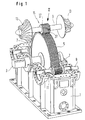
Figur 1- eine Verdichteranlage nach der Erfindung und
- Figur 2
- ein Planetengetreibe, welches beispielsweise an der Position II der Fig. 1 zwischen Ritzel und Zentralzahnrad eingeschaltet sein kann.
- Figure 1
- a compressor system according to the invention and
- Figure 2
- a planetary gear, which can be switched on, for example, at position II of FIG. 1 between the pinion and the central gear.
In Fig. 1 ist in perspektivischer Darstellung ein Teil einer Verdichteranlage gezeigt. Im unteren Teil eines Getriebegehäuses 1 ist ein drehfest mit einer Getriebeeingangswelle 3 verbundenes Hauptzahnrad 5 gelagert. Das Hauptzahnrad 5 treibt mehrere ebenfalls in dem Verdichtergehäuse 1 gelagerte Ritzel 7. Mit den Ritzeln 7 drehfest verbundene Ausgangswellen 9 erstrecken sich durch Lageröffnungen 11 des Gehäuses 1 hindurch über die Gehäusewände hinaus und können, wie an der obersten Ritzelwelle 9 gezeigt, an beiden Enden Läufer 13 von Verdichtern tragen. Das die in Fig. 1 oben liegende Ausgangswelle 9 antreibende Ritzel ist das Sonnenrad eines Planetengetriebes 15, dessen Hohlrad 17 eine Außenverzahnung aufweist und zum Antrieb der Ausgangswelle 9 mit dem als Zentralrad ausgebildeten Hauptzahnrads 5 kämmt.In Fig. 1, a part of a compressor system is shown in perspective. In the lower part of a
In Fig. 2 ist das Planetengetriebe 15 zusammen mit einem Teil des Hauptzahnrads 5 und des Getriebegehäuses 1 im Schnitt dargestellt. Die Ausgangswelle 9 ist drehfest mit einem Sonnenrad 19 verbunden und erstreckt sich durch die Lageröffnung 11 des Gehäuses 1 hindurch nach außen. Wie in Fig. 2 gezeigt, kämmt das Sonnenrad 19 mit Planetenrädern, die in dem relativ zum Gehäuse 1 festgelegten Planetenradträger 23 drehbar gelagert sind. Das Planetenrad 21 überträgt die Drehung des vom Hauptzahnrad 5 angetriebenen Hohlrads 17 auf das Sonnenrad 19. Mittels eines Schrägkugellagers 25 ist das Hohlrad 17 am drehfesten Planetenradträger 23 drehbar gelagert. Das Hohlrad 17 weist zum Eingriff mit der Schrägverzahnung des Hauptzahnrads 5 eine schräge Außenverzahnung 27 auf sowie an ihrem Innenumfang eine mit dem Planetenrad 21 kämmende, in diesem Fall gerade Innenverzahnung 29.In Fig. 2, the
Das in diesem Beispiel gezeigte Planetengetriebe 15 hat ein Übersetzungsverhältnis zwischen der Drehzahl des Hauptzahnrads 5 und der Drehzahl der Ausgangswelle 9 von 23,5. Dies bedeutet bei einer Hauptzahnraddrehzahl von 2.980 min-1 eine Ausgangswellendrehzahl von 70.000 min-1 mit einer Drehzahl des Hohlrads 17 von 13.708 min-1 und einer Drehzahl der Planetenräder 21 von 34.000 min-1. Bei einer derart hohen Ausgangswellendrehzahl ist es nicht nur eine konstruktive Notwendigkeit zur Unterbringung des Planetengetriebes 15, sondern sogar höchst erwünscht, den Durchmesser der Sonnenradausgangswelle 9 klein zu halten. Dadurch lassen sich die in einem die Welle 9 lagernden Ölfilm-Gleitlager 31 auftretenden Reibungsverluste wegen der dem Durchmesser der Ausgangswelle 9 proportionalen Umlaufgeschwindigkeit derselben relativ gering halten. Ein von den Verdichterläufern 13 herrührender resultierender Verdichteraxialschub auf die Ausgangswelle 9 wird über an der Ausgangswelle 9 fest angebrachte Druckkämme 33 auf die Planetenräder 21 übertragen. Wegen der durch ein Rillenkugellager 35 gebildeten axialkraftübertragenden Lageranordnung wird dieser axiale Verdichterschub auf den Planetenradträger 23 und damit letztlich auf das fest mit dem Planetenradträger 23 verbundene Getriebegehäuse 1 übertragen.The
Bei den in Fig. 1 gezeigten, direkt mit dem Hauptzahnrad 5 kämmenden Ausgangswellenritzeln 7 mit Druckkamm, wird ein resultierender Verdichteraxialschub dagegen auf das Hauptzahnrad 5 übertragen.In the case of the
Da das Lager 31 der Planetengetriebeausgangswelle 9 in einer an die herkömmlichen Abmessungen der Lageröffnung 11 angepaßten Ausgangswellenlagereinheit 37 angeordnet ist, wird eine aufwendige Gehäuseneukonstruktion vermieden. Die Ausgangswellenlagereinheit 37 weist einen Lageraußenteil 39 auf, der die feste Verbindung zwischen dem Getriebegehäuse 1 und dem Planetenradträger 23 herstellt.Since the bearing 31 of the planetary
Da die in dem Planetengetriebe 15 übertragenen Drehmomente wesentlich kleiner sind als die Drehmomente, die von dem Hauptzahnrad 5 auf die Außenverzahnung des Hohlrads 17 übertragen werden, kann die axiale Breite der Verzahnungen im Inneren des Planetengetriebes 15 kleiner sein als die axiale Breite des Hauptzahnrads 5. Aus diesem Grunde kann das Planetengetriebe 15 axial besonders kompakt sein und somit in Gehäusen mit relativ geringer Breite eingebaut werden. Solche relativ schmalen Gehäuse sind im Hinblick auf Biegeschwingungen der in den Gehäusewänden gelagerten Wellen besonders vorteilhaft.Since the torques transmitted in the
Das Hohlrad 17 ist über einen axial nur geringfügig über das Zentralrad hinausragenden, sich radial auf die Sonnenradwelle 9 zu erstreckenden Hohlradträgerflansch 41 über das Schrägkugellager 25 an einem Trägerhals 43 des Planetenradträgers 23 gelagert. In axialer Richtung liegt der Hohlradträgerflansch 41 zwischen einem Stützring 45 des Lageraußenteils 39 und einem die Planetenräder 21 tragenden Planetenradträgerflansch 47, der innerhalb der axialen Breite des Hauptzahnrads 5 angeordnet ist.The
Der Trägerhals 43 des Planetenradträgers 23 ist mittels Schrauben 44 an dem Stützring 45 der Ausgangswellenlagereinheit 37 befestigt, und der Stützring 45 ist durch Schrauben 46 an dem Gehäuse 1 befestigt.The support neck 43 of the
Das Lageraußenteil 39 der Ausgangswellenlagereinheit 37 und der Planetenradträger 23 sowie der Hohlradträgerflansch 41 können durch Druckguß erzeugt sein, was sich im Hinblick auf komplizierte Formen, Ölversorgungskanäle usw. als besonders günstig erweist.The
In dem Planetengetriebe 15 sind bevorzugterweise drei in Umfangsrichtung gleichmäßig um die Sonnenradwelle 9 angeordnete Planetenräder 21 vorgesehen, so daß sich die über die Planetenräder 21 auf die Sonnenradwelle 9 übertragenen radialen Kräfte weitgehend kompensieren. Diese Planetenräder 21 können aus Kunststoff hergestellt sein.In the
Die erfindungsgemäße Verdichteranlage bietet also bei kompakter Bauweise sehr hohe Übersetzungen und ermöglicht damit sehr hohe Ausgangsdrücke eines in dieser Anlage verdichteten Mediums.The compressor system according to the invention thus offers very high ratios with a compact design and thus enables very high outlet pressures of a medium compressed in this system.
Claims (21)
- A compressor system having a toothed wheel gear unit inserted in the drive train between a drive unit and a compressor region of the system, said toothed wheel gear unit comprising a transmission housing (1), a transmission input shaft (3) being supported in this transmission housing (1), a main gearwheel (5) near the input and at least one output shaft (9) with an axis, driven by the main gearwheel (5) by way of a pinion (7,19) and leading to the compressor region,
characterized in thatthe pinion driving the output shaft (9) is composed of a sun gear (19) of a planetary gear (15),wherein a planet carrier (23) of this planetary gear (15) is fixed to the transmission housing (1),wherein further a ring gear (17) of this planetary gear (15) is rotatably supported on a bearing part (43) that is stationary with respect to the transmission housing (1), the ring gear (17) having outer teeth (27),wherein further said ring gear (17) comprises outer teeth (27)being in engagement with the main gearwheel (5) near the input,wherein further at least one planet gear (21) is supported on the planet carrier (23) and is in toothed engagement with inner teeth (29) of the ring gear (17) and with outer teeth of the sun gear (19),wherein further the sun gear (19) or/and said output shaft (9) are fixed in the axial direction by at least one pressure plate (33) at the at least one planet gear (21), andwherein said at least one planet gear (21) is supported in the axial direction on the planet carrier (23) by an axial force-transmitting bearing arrangement (35). - The compressor system according to claim 1,
characterized in that
said at least one pressure plate (33) engages said at least one planet gear (21) in radial vicinity to the pitch circle of the teeth of the planet gear (21). - The compressor system according to claim 1 or 2,
characterized in that said output shaft (9) is supported by an output shaft bearing unit (37) in a bearing opening (11) of a side wall of the transmission housing (1), said output shaft bearing unit (37) comprising an outer bearing part (39) fixed on the transmission housing (1) in both the axial and circumferential directions. - The compressor system according to claim 3,
characterized in that
the bearing opening (11) is oversized with respect to the diameter of the output shaft (9), the output shaft bearing unit (37) being dimensioned to compensate for said oversizing. - The compressor system according to one of claims 3 or 4,
characterized in that
the output shaft bearing unit (37) is designed as a sliding bearing (31), in particular with a bearing oil film. - The compressor system according to one of claims 3 to 5,
characterized in that
the planet carrier (23) is fastened to the outer bearing part (39) of the output shaft bearing unit (37). - The compressor system according to claim 6,
characterized in that
the ring gear (17) is supported on the planet carrier (23). - The compressor system according to claim 7,
characterized in that
the outer teeth (27) of the ring gear (17) are designed as plain helical teeth, and in that the ring gear (17), at at least one axial end thereof, is supported on the planet carrier (23) by an axial force-transmitting ball bearing, in particular an angular ball bearing (25). - The compressor system according to one of claims 1 to 8,
characterized in that
said at least one planet gear (21) is supported on the planet carrier (23) by at least one axial force-transmitting bearing, in particular a groove ball bearing (35). - The compressor system according to one of claims 3 to 9,
characterized in that
the outer bearing part (39) of the output shaft bearing unit (37) includes a support ring (45) resting on the inside of the housing wall in the peripheral region of the bearing opening (11), that a carrier neck (43) of the planet carrier (23) is fastened to this support ring (45) in a radially inner region thereof, that this carrier neck (43) of the planet carrier (23), at an end near the planet gear, includes a planet carrier flange (47) extending radially outward, and that a ring gear carrier flange (41), extending radially inward, is supported on the carrier neck (43) of the planet carrier (23) axially between the planet carrier flange (47) and the support ring (45). - The compressor system according to one of claims 1 to 8,
characterized in that
the ring gear (17) is composed of an outer ring, having outer teeth (27) and inner teeth (29), and a ring gear carrier flange (41) fastened detachably to the outer ring, the ring gear carrier flange (41) being fixed to at least one axial end of the outer ring. - The compressor system according to one of claims 1 to 11,
characterized in that
the teeth of the sun gear (19) and said at least one planet gear (21) are straight teeth. - The compressor system according to one of claims 1 to 12,
characterized in that
said at least one planet gear (21) is made of synthetic material. - The compressor system according to one of claims 1 to 13,
characterized in that
the inner teeth (29) of the ring gear (17) have an axial width which is smaller than the axial width of the main gearwheel (5), and that at least part of the axial width of the planet carrier (23) is accommodated in an axially overlapping relationship with the axial width of the main gearwheel (5) . - The compressor system according to one of claims 1 to 14,
characterized in that
the planetary gear (15) and the bearings thereof are accommodated, substantially symmetrical to a plane of symmetry orthogonal with reference to the axis of the output shaft, between two housing walls of the transmission housing (1). - The compressor system according to one of claims 1 to 15,
characterized in that
said output shaft (9) extends through two housing walls of the transmission housing facing each other. - The compressor system according to one of claims 1 to 16,
characterized in that,
at at least one end, said output shaft (9) carries the rotor (13) of a compressor, in particular of a turbocompressor or screw-type compressor. - The compressor system according to one of claims 1 to 17,
characterized in that
a pair of compressor units (13) are connected with the two ends of one output shaft (9) so that axial thrusts transmitted by said compressor units (13) to said output shaft (9) are at least partially offset. - The compressor system according to one of claims 1 to 18,
characterized in that
the main gearwheel (5) is arranged as a central wheel in the transmission housing (1), and that bearings (11) for a plurality of output shafts (9) are distributed about the axis of the central wheel (5) and mounted in the transmission housing (1). - The compressor system according to claim 19,
characterized in that
an output shaft (9), having an associated pinion (7) in direct toothed engagement with the main gearwheel (5), is supported in at least one of the bearings (11). - The compressor system according to one of claims 1 to 20,
characterized in that
the main gearwheel (5) is connected in a rotationally fixed manner to the input shaft (3).
Applications Claiming Priority (2)
| Application Number | Priority Date | Filing Date | Title |
|---|---|---|---|
| DE4241141 | 1992-12-07 | ||
| DE4241141A DE4241141A1 (en) | 1992-12-07 | 1992-12-07 | Compressor system with a gear transmission engaged in the drive train between a drive unit and a compressor area of the system |
Publications (2)
| Publication Number | Publication Date |
|---|---|
| EP0602491A1 EP0602491A1 (en) | 1994-06-22 |
| EP0602491B1 true EP0602491B1 (en) | 1996-10-09 |
Family
ID=6474585
Family Applications (1)
| Application Number | Title | Priority Date | Filing Date |
|---|---|---|---|
| EP93119606A Expired - Lifetime EP0602491B1 (en) | 1992-12-07 | 1993-12-06 | Transmission and compressor system |
Country Status (3)
| Country | Link |
|---|---|
| US (1) | US5382132A (en) |
| EP (1) | EP0602491B1 (en) |
| DE (2) | DE4241141A1 (en) |
Cited By (1)
| Publication number | Priority date | Publication date | Assignee | Title |
|---|---|---|---|---|
| DE102013208564A1 (en) | 2013-05-08 | 2014-11-13 | Voith Patent Gmbh | Transmission and transmission compressor system |
Families Citing this family (41)
| Publication number | Priority date | Publication date | Assignee | Title |
|---|---|---|---|---|
| US5402631A (en) * | 1991-05-10 | 1995-04-04 | Praxair Technology, Inc. | Integration of combustor-turbine units and integral-gear pressure processors |
| DE4234739C1 (en) * | 1992-10-15 | 1993-11-25 | Gutehoffnungshuette Man | Gearbox multi-shaft turbo compressor with feedback stages |
| DE4436710C2 (en) * | 1994-10-14 | 1997-04-03 | Gutehoffnungshuette Man | Gearbox multi-shaft turbo machine |
| JPH09119378A (en) * | 1995-10-25 | 1997-05-06 | Ishikawajima Harima Heavy Ind Co Ltd | Turbo compressor |
| ES2177162T3 (en) * | 1998-03-26 | 2002-12-01 | Uhde Gmbh | PROCEDURE AND INSTALLATION FOR PREPARATION OF NITRIC ACID. |
| US6692234B2 (en) | 1999-03-22 | 2004-02-17 | Water Management Systems | Pump system with vacuum source |
| DE10003018B4 (en) * | 2000-01-25 | 2009-09-24 | Atlas Copco Energas Gmbh | Turbo compressor |
| GB2371339B (en) * | 2001-01-19 | 2003-05-07 | Visteon Global Tech Inc | Multi-speed gear arrangement for a centrifugal engine charger |
| SE519200C2 (en) * | 2001-06-05 | 2003-01-28 | Volvo Aero Corp | Gas turbine device with an arrangement for operating one or more auxiliary appliances |
| US7189068B2 (en) | 2003-09-19 | 2007-03-13 | Gast Manufacturing, Inc. | Sound reduced rotary vane compressor |
| DE102005002702A1 (en) * | 2005-01-19 | 2006-07-27 | Man Turbo Ag | Multi-stage turbocompressor |
| EP1957798B1 (en) | 2005-12-08 | 2011-02-09 | GHH-RAND Schraubenkompressoren GmbH | Helical screw compressor |
| US8342829B2 (en) * | 2005-12-08 | 2013-01-01 | Ghh Rand Schraubenkompressoren Gmbh | Three-stage screw compressor |
| KR100873043B1 (en) * | 2007-03-30 | 2008-12-09 | 삼성테크윈 주식회사 | Gear case assembly |
| DE102008031116B4 (en) * | 2008-05-29 | 2022-02-03 | Man Energy Solutions Se | Geared turbomachine for a machine train, machine train with and gear for geared turbomachine |
| DE102008038787A1 (en) * | 2008-08-13 | 2010-02-18 | Siemens Aktiengesellschaft | Fluid energy machine |
| US8998586B2 (en) * | 2009-08-24 | 2015-04-07 | David Muhs | Self priming pump assembly with a direct drive vacuum pump |
| IT1398142B1 (en) * | 2010-02-17 | 2013-02-14 | Nuovo Pignone Spa | SINGLE SYSTEM WITH COMPRESSOR AND INTEGRATED PUMP AND METHOD. |
| KR101009742B1 (en) * | 2010-10-29 | 2011-01-19 | 주식회사 세진아이지비 | A transmission device for converting a torque |
| DE102011003525A1 (en) * | 2011-02-02 | 2012-08-02 | Siemens Aktiengesellschaft | Stepped parting line on a gearbox |
| JP5863320B2 (en) | 2011-08-05 | 2016-02-16 | 三菱重工コンプレッサ株式会社 | Centrifugal compressor |
| DE102012018468B4 (en) * | 2012-09-19 | 2022-07-14 | Man Energy Solutions Se | geared turbomachine |
| DE102012217441A1 (en) * | 2012-09-26 | 2014-03-27 | Siemens Aktiengesellschaft | geared compressors |
| US9017046B2 (en) * | 2013-01-02 | 2015-04-28 | Elijah Anim Owusu | Fan assembly having multiple centrifugal fans in mechanical connection with a planetary gear system |
| DE102013210497A1 (en) | 2013-06-06 | 2014-12-11 | Siemens Aktiengesellschaft | geared compressors |
| US10145381B2 (en) * | 2014-01-23 | 2018-12-04 | Mitsubishi Heavy Industries Compressor Corporation | Geared centrifugal compressor with pressure adjustment portion to balance axial thrust |
| US20150211539A1 (en) | 2014-01-24 | 2015-07-30 | Air Products And Chemicals, Inc. | Systems and methods for compressing air |
| CN104005966A (en) * | 2014-05-29 | 2014-08-27 | 安徽银龙泵阀股份有限公司 | Multi-spindle pump core capable of rotating by means of star gear principle |
| CN106574626A (en) * | 2014-09-18 | 2017-04-19 | 三菱重工压缩机有限公司 | Compressor system |
| DE102014219137A1 (en) * | 2014-09-23 | 2016-03-24 | Siemens Aktiengesellschaft | Sealing element for stepped part joints on gearbox housings |
| DE102014221339A1 (en) * | 2014-10-21 | 2016-04-21 | Siemens Aktiengesellschaft | Stepped parting line on a gearbox |
| KR102500189B1 (en) | 2014-11-21 | 2023-02-14 | 보이트 파텐트 게엠베하 | Transmission and transmission turbomachine |
| DE102015225923A1 (en) * | 2014-12-19 | 2016-06-23 | Voith Patent Gmbh | Housing for a transmission, in particular integral transmission |
| JP6395683B2 (en) * | 2015-09-02 | 2018-09-26 | 株式会社神戸製鋼所 | Compressor |
| WO2018019613A1 (en) | 2016-07-26 | 2018-02-01 | Voith Patent Gmbh | Drive device with speed modulation gearbox |
| DE102017103695A1 (en) | 2017-02-23 | 2018-08-23 | Voith Patent Gmbh | Drive device with superposition gear |
| DE102017103696A1 (en) | 2017-02-23 | 2018-08-23 | Voith Patent Gmbh | Drive device with superposition gear |
| CN109372776A (en) * | 2018-11-26 | 2019-02-22 | 黄莲英 | A kind of indood ventilation fan that leaving area is big |
| CN109779920B (en) * | 2019-03-11 | 2020-12-08 | 衢州学院 | Two-stage speed-increasing peripheral pump device based on planetary gear train |
| DE102021120100A1 (en) | 2021-08-03 | 2023-02-09 | Voith Patent Gmbh | spur gear |
| JP2023123909A (en) * | 2022-02-25 | 2023-09-06 | 三菱重工コンプレッサ株式会社 | geared compressor |
Family Cites Families (15)
| Publication number | Priority date | Publication date | Assignee | Title |
|---|---|---|---|---|
| DE7323092U (en) * | 1974-03-07 | Bhs Ag | Compressor gearbox | |
| US1435821A (en) * | 1920-11-29 | 1922-11-14 | North East Electric Co | Epicycloidal gearing |
| US2403381A (en) * | 1944-07-19 | 1946-07-02 | Bendix Aviat Corp | Regulated system |
| US3001692A (en) * | 1949-07-26 | 1961-09-26 | Schierl Otto | Multistage compressors |
| DE1095700B (en) * | 1958-06-06 | 1960-12-22 | Iaweseria Ag | Marine gear |
| FR1205150A (en) * | 1958-07-03 | 1960-01-29 | Power amplifier by combined transmissions and in particular for automobiles | |
| GB1000877A (en) * | 1962-06-30 | 1965-08-11 | Ckd Praha | Improvements in or relating to rotary blowers or compressors |
| DE2113594A1 (en) * | 1971-03-20 | 1972-10-12 | Gutehoffnungshuette Sterkrade | Spur gear overlay gear |
| DE2256681B2 (en) * | 1972-11-18 | 1976-05-26 | Demag Ag, 4100 Duisburg | GEARBOX FOR TURBO COMPRESSOR |
| FR2234490A1 (en) * | 1973-06-20 | 1975-01-17 | Bhs Bayerische Berg | Compressor drive gear with central wheel - has pinion shafts equipped with thrust rings |
| DD158489A3 (en) * | 1981-02-25 | 1983-01-19 | Helmut Paulat | GEARBOX, ESPECIALLY FOR MULTIWAVE COMPRESSORS |
| JPH01267397A (en) * | 1988-04-15 | 1989-10-25 | Hitachi Ltd | Centrifugal compressor |
| DE4003482A1 (en) * | 1990-02-06 | 1991-08-08 | Borsig Babcock Ag | GEARBOX TURBO COMPRESSOR |
| DE9201858U1 (en) * | 1992-02-11 | 1992-04-02 | Mannesmann Ag, 4000 Duesseldorf, De | |
| DE4204338C2 (en) * | 1992-02-11 | 1993-11-18 | Mannesmann Ag | Gearbox turbo compressor |
-
1992
- 1992-12-07 DE DE4241141A patent/DE4241141A1/en not_active Ceased
-
1993
- 1993-11-10 US US08/150,695 patent/US5382132A/en not_active Expired - Lifetime
- 1993-12-06 EP EP93119606A patent/EP0602491B1/en not_active Expired - Lifetime
- 1993-12-06 DE DE59304119T patent/DE59304119D1/en not_active Expired - Fee Related
Cited By (1)
| Publication number | Priority date | Publication date | Assignee | Title |
|---|---|---|---|---|
| DE102013208564A1 (en) | 2013-05-08 | 2014-11-13 | Voith Patent Gmbh | Transmission and transmission compressor system |
Also Published As
| Publication number | Publication date |
|---|---|
| EP0602491A1 (en) | 1994-06-22 |
| US5382132A (en) | 1995-01-17 |
| DE59304119D1 (en) | 1996-11-14 |
| DE4241141A1 (en) | 1994-06-09 |
Similar Documents
| Publication | Publication Date | Title |
|---|---|---|
| EP0602491B1 (en) | Transmission and compressor system | |
| EP1000280B1 (en) | Modular gear system with contrate gear | |
| AT394757B (en) | PTO OF AN INTERNAL COMBUSTION ENGINE | |
| EP1110011B1 (en) | Multi-stage spur gear transmission | |
| EP1098063B1 (en) | Tubular motor | |
| DE102016118877B4 (en) | Mechanical gear arrangement | |
| EP1252444B1 (en) | Drive mechanism for a screw pump | |
| EP1574316A1 (en) | Drive for a twin-screw extruder | |
| EP3351826B1 (en) | Compact multi-stage transmission comprising a planetary gear and a subsequent shaft drive | |
| EP0736692B1 (en) | Sealing, bearing support and driving of the rotors of a dry running screw compressor | |
| EP2271858B1 (en) | Transmission and differential device | |
| CH665893A5 (en) | PLANETARY GEARBOX THROUGH A FLUID MACHINE AND AN ELECTRICAL MACHINE IN A GEARBOX HOUSING. | |
| DD141941A5 (en) | INTERIOR MACHINE WITH SCREW FEW PROFILE AT ROTOR AND STATOR | |
| DE2403016A1 (en) | GEAR FOR A SPEED BLOWER WITH VARIABLE BLADE PITCH | |
| DE102019124666B4 (en) | Differential gear | |
| DE102004002052B4 (en) | The wave gear | |
| DE2839749C2 (en) | Gear group to be arranged in the longitudinal direction of the motor vehicle | |
| EP3768994A1 (en) | Planetary gearbox having single-tooth sun gear having evoloid toothing | |
| DE4204338C2 (en) | Gearbox turbo compressor | |
| EP1502792B1 (en) | Drive unit for reciprocating floor conveyor | |
| DE3941719A1 (en) | Epicyclic gear train - has blocks for planetary pinions at intervals round planet-carrier periphery | |
| DD294763A5 (en) | TRANSMISSION | |
| EP1067291B1 (en) | Transmission and centrifugal compressor | |
| EP0622544A1 (en) | Adjusting mechanism for axial-flow pump blades | |
| EP0395980A1 (en) | Lifting gear |
Legal Events
| Date | Code | Title | Description |
|---|---|---|---|
| PUAI | Public reference made under article 153(3) epc to a published international application that has entered the european phase |
Free format text: ORIGINAL CODE: 0009012 |
|
| AK | Designated contracting states |
Kind code of ref document: A1 Designated state(s): CH DE FR GB LI |
|
| 17P | Request for examination filed |
Effective date: 19940623 |
|
| 17Q | First examination report despatched |
Effective date: 19950619 |
|
| RAP1 | Party data changed (applicant data changed or rights of an application transferred) |
Owner name: BHS-BAYERISCHE BERG-, HUETTEN- UND SALZWERKE AKTIE |
|
| GRAH | Despatch of communication of intention to grant a patent |
Free format text: ORIGINAL CODE: EPIDOS IGRA |
|
| GRAA | (expected) grant |
Free format text: ORIGINAL CODE: 0009210 |
|
| RAP1 | Party data changed (applicant data changed or rights of an application transferred) |
Owner name: BHS-CINCINNATI GETRIEBETECHNIK GMBH |
|
| AK | Designated contracting states |
Kind code of ref document: B1 Designated state(s): CH DE FR GB LI |
|
| REG | Reference to a national code |
Ref country code: CH Ref legal event code: NV Representative=s name: E. BLUM & CO. PATENTANWAELTE |
|
| GBT | Gb: translation of ep patent filed (gb section 77(6)(a)/1977) |
Effective date: 19961010 |
|
| REF | Corresponds to: |
Ref document number: 59304119 Country of ref document: DE Date of ref document: 19961114 |
|
| ET | Fr: translation filed | ||
| PLBI | Opposition filed |
Free format text: ORIGINAL CODE: 0009260 |
|
| PLBQ | Unpublished change to opponent data |
Free format text: ORIGINAL CODE: EPIDOS OPPO |
|
| PLBF | Reply of patent proprietor to notice(s) of opposition |
Free format text: ORIGINAL CODE: EPIDOS OBSO |
|
| 26 | Opposition filed |
Opponent name: RENK AKTIENGESELLSCHAFT Effective date: 19970630 |
|
| PLBF | Reply of patent proprietor to notice(s) of opposition |
Free format text: ORIGINAL CODE: EPIDOS OBSO |
|
| PLBQ | Unpublished change to opponent data |
Free format text: ORIGINAL CODE: EPIDOS OPPO |
|
| PLAB | Opposition data, opponent's data or that of the opponent's representative modified |
Free format text: ORIGINAL CODE: 0009299OPPO |
|
| R26 | Opposition filed (corrected) |
Opponent name: RENK AKTIENGESELLSCHAFT Effective date: 19970630 |
|
| PLBO | Opposition rejected |
Free format text: ORIGINAL CODE: EPIDOS REJO |
|
| PLBN | Opposition rejected |
Free format text: ORIGINAL CODE: 0009273 |
|
| STAA | Information on the status of an ep patent application or granted ep patent |
Free format text: STATUS: OPPOSITION REJECTED |
|
| 27O | Opposition rejected |
Effective date: 19981017 |
|
| PGFP | Annual fee paid to national office [announced via postgrant information from national office to epo] |
Ref country code: FR Payment date: 19991015 Year of fee payment: 7 Ref country code: DE Payment date: 19991015 Year of fee payment: 7 |
|
| PGFP | Annual fee paid to national office [announced via postgrant information from national office to epo] |
Ref country code: CH Payment date: 19991109 Year of fee payment: 7 |
|
| PGFP | Annual fee paid to national office [announced via postgrant information from national office to epo] |
Ref country code: GB Payment date: 19991201 Year of fee payment: 7 |
|
| PG25 | Lapsed in a contracting state [announced via postgrant information from national office to epo] |
Ref country code: GB Free format text: LAPSE BECAUSE OF NON-PAYMENT OF DUE FEES Effective date: 20001206 |
|
| PG25 | Lapsed in a contracting state [announced via postgrant information from national office to epo] |
Ref country code: LI Free format text: LAPSE BECAUSE OF NON-PAYMENT OF DUE FEES Effective date: 20001231 Ref country code: CH Free format text: LAPSE BECAUSE OF NON-PAYMENT OF DUE FEES Effective date: 20001231 |
|
| GBPC | Gb: european patent ceased through non-payment of renewal fee |
Effective date: 20001206 |
|
| REG | Reference to a national code |
Ref country code: CH Ref legal event code: PL |
|
| PG25 | Lapsed in a contracting state [announced via postgrant information from national office to epo] |
Ref country code: FR Free format text: LAPSE BECAUSE OF NON-PAYMENT OF DUE FEES Effective date: 20010831 |
|
| REG | Reference to a national code |
Ref country code: FR Ref legal event code: ST |
|
| PG25 | Lapsed in a contracting state [announced via postgrant information from national office to epo] |
Ref country code: DE Free format text: LAPSE BECAUSE OF NON-PAYMENT OF DUE FEES Effective date: 20011002 |