EP0602425B2 - Dispositif de cylindre à force variable - Google Patents
Dispositif de cylindre à force variable Download PDFInfo
- Publication number
- EP0602425B2 EP0602425B2 EP93118950A EP93118950A EP0602425B2 EP 0602425 B2 EP0602425 B2 EP 0602425B2 EP 93118950 A EP93118950 A EP 93118950A EP 93118950 A EP93118950 A EP 93118950A EP 0602425 B2 EP0602425 B2 EP 0602425B2
- Authority
- EP
- European Patent Office
- Prior art keywords
- piston
- small
- bore portion
- diameter portion
- stroke
- Prior art date
- Legal status (The legal status is an assumption and is not a legal conclusion. Google has not performed a legal analysis and makes no representation as to the accuracy of the status listed.)
- Expired - Lifetime
Links
- 239000012530 fluid Substances 0.000 claims description 47
- 230000001174 ascending effect Effects 0.000 claims 4
- 230000003993 interaction Effects 0.000 claims 3
- 238000007789 sealing Methods 0.000 description 23
- 230000002093 peripheral effect Effects 0.000 description 13
- 230000000694 effects Effects 0.000 description 5
- 208000027418 Wounds and injury Diseases 0.000 description 4
- 238000013459 approach Methods 0.000 description 4
- 238000004891 communication Methods 0.000 description 4
- 230000006378 damage Effects 0.000 description 4
- 208000014674 injury Diseases 0.000 description 4
- 230000008602 contraction Effects 0.000 description 1
- 238000006073 displacement reaction Methods 0.000 description 1
- 238000012986 modification Methods 0.000 description 1
- 230000004048 modification Effects 0.000 description 1
Images
Classifications
-
- F—MECHANICAL ENGINEERING; LIGHTING; HEATING; WEAPONS; BLASTING
- F15—FLUID-PRESSURE ACTUATORS; HYDRAULICS OR PNEUMATICS IN GENERAL
- F15B—SYSTEMS ACTING BY MEANS OF FLUIDS IN GENERAL; FLUID-PRESSURE ACTUATORS, e.g. SERVOMOTORS; DETAILS OF FLUID-PRESSURE SYSTEMS, NOT OTHERWISE PROVIDED FOR
- F15B15/00—Fluid-actuated devices for displacing a member from one position to another; Gearing associated therewith
- F15B15/08—Characterised by the construction of the motor unit
- F15B15/14—Characterised by the construction of the motor unit of the straight-cylinder type
-
- B—PERFORMING OPERATIONS; TRANSPORTING
- B25—HAND TOOLS; PORTABLE POWER-DRIVEN TOOLS; MANIPULATORS
- B25B—TOOLS OR BENCH DEVICES NOT OTHERWISE PROVIDED FOR, FOR FASTENING, CONNECTING, DISENGAGING OR HOLDING
- B25B5/00—Clamps
- B25B5/06—Arrangements for positively actuating jaws
- B25B5/12—Arrangements for positively actuating jaws using toggle links
- B25B5/122—Arrangements for positively actuating jaws using toggle links with fluid drive
-
- B—PERFORMING OPERATIONS; TRANSPORTING
- B25—HAND TOOLS; PORTABLE POWER-DRIVEN TOOLS; MANIPULATORS
- B25B—TOOLS OR BENCH DEVICES NOT OTHERWISE PROVIDED FOR, FOR FASTENING, CONNECTING, DISENGAGING OR HOLDING
- B25B5/00—Clamps
- B25B5/06—Arrangements for positively actuating jaws
- B25B5/061—Arrangements for positively actuating jaws with fluid drive
-
- F—MECHANICAL ENGINEERING; LIGHTING; HEATING; WEAPONS; BLASTING
- F15—FLUID-PRESSURE ACTUATORS; HYDRAULICS OR PNEUMATICS IN GENERAL
- F15B—SYSTEMS ACTING BY MEANS OF FLUIDS IN GENERAL; FLUID-PRESSURE ACTUATORS, e.g. SERVOMOTORS; DETAILS OF FLUID-PRESSURE SYSTEMS, NOT OTHERWISE PROVIDED FOR
- F15B11/00—Servomotor systems without provision for follow-up action; Circuits therefor
- F15B11/02—Systems essentially incorporating special features for controlling the speed or actuating force of an output member
- F15B11/024—Systems essentially incorporating special features for controlling the speed or actuating force of an output member by means of differential connection of the servomotor lines, e.g. regenerative circuits
-
- F—MECHANICAL ENGINEERING; LIGHTING; HEATING; WEAPONS; BLASTING
- F15—FLUID-PRESSURE ACTUATORS; HYDRAULICS OR PNEUMATICS IN GENERAL
- F15B—SYSTEMS ACTING BY MEANS OF FLUIDS IN GENERAL; FLUID-PRESSURE ACTUATORS, e.g. SERVOMOTORS; DETAILS OF FLUID-PRESSURE SYSTEMS, NOT OTHERWISE PROVIDED FOR
- F15B11/00—Servomotor systems without provision for follow-up action; Circuits therefor
- F15B11/02—Systems essentially incorporating special features for controlling the speed or actuating force of an output member
- F15B11/028—Systems essentially incorporating special features for controlling the speed or actuating force of an output member for controlling the actuating force
- F15B11/036—Systems essentially incorporating special features for controlling the speed or actuating force of an output member for controlling the actuating force by means of servomotors having a plurality of working chambers
-
- F—MECHANICAL ENGINEERING; LIGHTING; HEATING; WEAPONS; BLASTING
- F15—FLUID-PRESSURE ACTUATORS; HYDRAULICS OR PNEUMATICS IN GENERAL
- F15B—SYSTEMS ACTING BY MEANS OF FLUIDS IN GENERAL; FLUID-PRESSURE ACTUATORS, e.g. SERVOMOTORS; DETAILS OF FLUID-PRESSURE SYSTEMS, NOT OTHERWISE PROVIDED FOR
- F15B15/00—Fluid-actuated devices for displacing a member from one position to another; Gearing associated therewith
- F15B15/08—Characterised by the construction of the motor unit
- F15B15/14—Characterised by the construction of the motor unit of the straight-cylinder type
- F15B15/1404—Characterised by the construction of the motor unit of the straight-cylinder type in clusters, e.g. multiple cylinders in one block
-
- F—MECHANICAL ENGINEERING; LIGHTING; HEATING; WEAPONS; BLASTING
- F15—FLUID-PRESSURE ACTUATORS; HYDRAULICS OR PNEUMATICS IN GENERAL
- F15B—SYSTEMS ACTING BY MEANS OF FLUIDS IN GENERAL; FLUID-PRESSURE ACTUATORS, e.g. SERVOMOTORS; DETAILS OF FLUID-PRESSURE SYSTEMS, NOT OTHERWISE PROVIDED FOR
- F15B15/00—Fluid-actuated devices for displacing a member from one position to another; Gearing associated therewith
- F15B15/20—Other details, e.g. assembly with regulating devices
- F15B15/204—Control means for piston speed or actuating force without external control, e.g. control valve inside the piston
-
- F—MECHANICAL ENGINEERING; LIGHTING; HEATING; WEAPONS; BLASTING
- F16—ENGINEERING ELEMENTS AND UNITS; GENERAL MEASURES FOR PRODUCING AND MAINTAINING EFFECTIVE FUNCTIONING OF MACHINES OR INSTALLATIONS; THERMAL INSULATION IN GENERAL
- F16J—PISTONS; CYLINDERS; SEALINGS
- F16J15/00—Sealings
- F16J15/16—Sealings between relatively-moving surfaces
- F16J15/164—Sealings between relatively-moving surfaces the sealing action depending on movements; pressure difference, temperature or presence of leaking fluid
Definitions
- This invention relates to a cylinder device, and more specifically to a variable force cylinder device in which a pressure-receiving area of a piston is altered depending on the travel distance of the piston in a cylinder chamber so that the force yielded by the piston is varied.
- a clamping device having a crank mechanism coupled to a cylinder device has been used to hold a workpiece.
- the document DE-A 20 05 472 discloses a working cylinder having a piston reciprocated by a pressurized fluid in a cylinder chamber. At both sides of the piston small diameter portions are provided to be received in corresponding small bore portions of the cylinder chamber at both ends thereof. As the length of the small bore portions and the corresponding small diameter portions is such that the small diameter portions of the piston are received in the small bore portions at the ends of the piston stroke only, it is evident that upon introduction of a pressurized fluid through the ports to move the piston in one direction or the other, it is only during the initial movement of the piston, that the fluid acts on the small diameter portions. Once the piston has cleared the rather short length of the small bore portions and thus for the majority of the stroke, the pressurized fluid acts on the large diameter portion of the piston with full force. Hence the danger of injury is not reduced.
- U.S. patent 2,293,334 discloses a check and unloading valve structure wherein a ram head is movable within a cylinder bore.
- the piston comprises a ram chamber movable together with the piston relative to a stationary piston head.
- pressure fluid first flows through the stationary piston head into the ram chamber acting on the relatively small diameter of booster area to move the piston relative to piston head.
- the piston has travelled forward to a point where ports connecting the ram chamber with the rearward end of the main cylinder, the fluid within the booster chamber escapes through the ports so that the pressure is exerted upon the large diameter of the piston.
- the document DE 28 13 694 A1 discloses a clamping device with a two-stage pressure cylinder wherein the pressure introduced into a port in a first phase of the piston stroke is transferred through a passage to a ring chamber to balance the pressures between the cylinder chamber and the ring chamber. Therefore, in a first phase of the stroke the effective force acting on the piston is reduced to the force acting on the area of the piston rod. In a final phase of the stroke, sealing elements seal the passage so that the effective pressure bearing area accounting for the clamping force is the complete area of the piston. In the passage a flap valve is located to prevent transfer of pressure fluid from the ring chamber into the cylinder chamber.
- An object of the present invention is to provide a variable force cylinder device which outputs the force, the strength of which is altered depending on the travel distance of the piston in the cylinder chamber to reduce the danger of injury for an operator.
- Such a cylinder device would be preferably used in a clamping device, for example, from a safety point of view as stated in the above.
- variable force cylinder device which comprises the features of claims 1, 2 or 5.
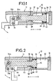
- FIG, 1 is a vertical cross-sectional view showing the manner of starting of a piston employed in a variable force cylinder device according to a first embodiment of the present invention.
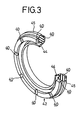
- FIG. 2 is a vertical cross-sectional view illustrating the manner in which the piston employed in the variable force cylinder device shown in FIG. 1, has been moved to a terminal position of the piston stroke.
- the variable force cylinder device 10 basically comprises a cylinder body 12, pressurized fluid discharge/intake ports 14 and 16 respectively defined in the cylinder body 12, a piston 20 slidably displaced in the direction indicated by an arrow A or B within a cylinder chamber 18 defined in the cylinder body 12, a piston rod 22 connected to the piston 20, and a bent arm 28 coupled to a leading end portion of the piston rod 22 by pins 24a and 24b and connected thereto so as to be rotatable in the direction indicated by an arrow about a crank pin 26.
- the cylinder chamber 18 has a large-bore portion 30 which communicates with the port 14, and a small-bore portion 32 which communicates with the port 16 and has an inner diameter smaller than that of the large-bore portion 30.
- the piston 20 reciprocates between the large-bore portion 30 and the small-bore portion 32.
- the piston 20 is made up of a large-diameter portion 34 having a large outer diameter and a small-diameter portion 36 having a small outer diameter.
- An annular groove 38 is defined in the large-diameter portion 34 of the piston 20 (see FIG. 4).
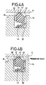
- a check valve 42 having a ring body in which a plurality of concave portions 40 are defined at predetermined intervals as shown in FIG. 3, is fitted in the annular groove 38.
- a bent portion 45 which has a tongue 44 provided on the inner periphery side of the check valve 42 and flexed or bent in the direction indicated by arrow and which is provided on the outer periphery side of the check valve 42, abuts against the peripheral wall surface of the large-bore portion 30.
- a seal ring 46 is mounted on the small-diameter portion 36 of the piston 20.
- the seal ring 46 is brought into contact with the wall surface of the small-bore portion 32 to carry out a sealing function.
- a annular clearance 48 is provided in the cylinder body 12 so as to communicate with the small-bore portion 32 and the port 16.
- variable force cylinder device 10 is basically constructed as described above. Operation of the variable force cylinder device 10 will next be described below.
- a pressurized fluid is first supplied from an unillustrated pressurized-fluid supply device to the variable force cylinder device 10 through the port 14.
- the port 16 is set to a half-opened state so as to allow the passage of a slight pressurized fluid by an unillustrated solenoid-controlled valve.
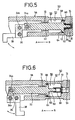
- the pressurized fluid introduced through the port 14 passes through the check valve 42 along a path indicated by an arrow in FIG. 4B so as to enter into the small-bore portion 32 on the piston rod 22 side.
- the large-bore portion 30 in the cylinder chamber 18 communicates with the small-bore portion 32, so that the front and rear pressures of the piston 20 are actually balanced.
- the pressurized fluid introduced into the small-bore portion 32 passes through the annular clearance 48 so as to be discharged into the outside through the port 16.
- the piston rod 22 moves in the direction indicated by the arrow A alike the piston 20 and the arm 28 is rotated a predetermined angle in the direction indicated by the arrow about the crank pin 26.
- the pressurized fluid passes through the annular clearance 48 and acts on a pressure-receiving surface of the small-diameter portion 36 of the piston 20.
- the piston 20 is displaced in the direction indicated by the arrow B and the seal ring 46 of the piston 20 reaches the large-bore portion 30, the sealing effect of the seal ring 46 is lost.
- the tongue 44 of the check valve 42 is flexed in the direction indicated by the arrow shown in FIG. 4A and prevents the pressurized fluid from leaking into the port 14 side. Accordingly, the piston 20 can travel to the original position shown in FIG. 1.
- FIGS. 5 and 6 A variable force cylinder device according to a second embodiment of the present invention will be shown in FIGS. 5 and 6.
- the same elements of structure employed in the first embodiment are identified by like reference numerals and their detailed description will therefore be omitted.
- the variable force cylinder device 50 comprises a cylinder body 58 having a cylinder chamber 56 made up of a large-bore portion 52 and a small-bore portion 54, and a piston 60 slidable displaced within the cylinder chamber 56 of the cylinder body 58.
- the piston 60 has a small-diameter portion 62 having a small pressure-receiving area and a large-diameter portion 64 having a large pressure-receiving area.
- a cylindrical member 66 which surrounds the small-diameter portion 62 and is elastically coupled to the small-diameter portion 62, is provided on the outer peripheral surface of the small-diameter portion 62 (see FIGS. 5 and 6).
- a ring-shaped sealing member 68 pressed against the cylinder chamber 56 is secured to the large-diameter portion 64 of the piston 60.
- a pressurized-fluid introduction hole 70 is defined in a leading end portion of the cylindrical member 66.
- a sealing member 72 which is brought into sliding contact with the outer peripheral surface of the cylindrical member 66, is provided within the small-bore portion 54 in the cylinder chamber 56.
- the pressurized fluid introduced through the port 14 of the variableforce cylinder device 50 according to the second embodiment is pressed against the pressure-receiving area of the small-diameter portion 62 through the introduction hole 70 of the cylindrical member 66 so as to move the piston 60 in the direction indicated by the arrow A. Since, the pressure-receiving area of the small-diameter portion 62 is small, the force acting on the piston 60 in the direction indicated by the arrow A is relatively weak.
- An arm 28 is rotated a predetermined angle about a crank pin 26 together with the displacement of the piston 60. Since, the sealing member 72 slides on the outer peripheral surface of the cylindrical member 66, a sealing effect is exhibited.
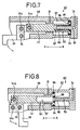
- variable force cylinder device 80 according to an embodiment not according to the present invention will now be illustrated in FIGS. 7 and 8.
- the variable force cylinder device 80 comprises a cylinder body 88 having a projection 86 with a communication path 84 communicating with a pressurized fluid discharge/intake port 14 defined in a cylinder chamber 82, and a piston 90 slidable displaced in the cylinder chamber 82 of the cylinder body 88.
- the piston 90 has a blind hole 92, whose bottom face acts as a small-diameter portion of the piston 90, in which the projection 86 can enter, and a large-diameter portion 94 having a large pressure-receiving area.
- a sealing member 96 pressed against the inner wall of the cylinder chamber 82 is mounted on the large-diameter portion 94 of the piston 90, whereas a sealing member 98 brought into sliding contact with the outer peripheral surface of the projection 86 is provided at an entrance position of the blind hole 92.
- the cylinder chamber 82 is set to the same diameter unlike the variable force cylinder devices according to the aforementioned embodiments.
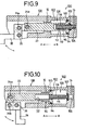
- variable force cylinder device 100 according to a fourth embodiment of the present invention will next be shown in FIGS. 9 and 10.
- the variable force cylinder device 100 comprises a cylinder body 108 having a cylinder chamber 106 comprised of a large-bore portion 102 and a small-bore portion 104.
- a piston 110 has a blind hole 112 having the bottom face as a small pressure-receiving area and a large-diameter portion 114 having a large pressure-receiving area.
- a rod member 118 having a communication path 116 defined therein, which communicates with a pressurized fluid discharge/intake port 14, is slidably fitted in the blind hole 112 so as to be capable of expansion or contraction.
- a sealing member 120 pressed against the large-bore portion 102 in the cylinder chamber 106 is mounted on the large-diameter portion 114 of the piston 110, whereas a sealing member 122 brought into sliding contact with the outer peripheral surface of the rod member 118 is provided inside of the small-bore portion 104.
- variable force cylinder device 100 Operation of the variable force cylinder device 100 according to the fourth embodiment will now be described below.
- a pressurized fluid introduced through the port 14 acts on the bottom face of the blind hole 112 having the small pressure-receiving area through the communication path 116 of the rod member 118 to thereby move the piston 110 in the direction indicated by an arrow A. Since the pressure-receiving area of the blind hole 112 is small, the force acting on the piston 110 in the direction of termination of its stroke is relatively weak.
- the sealing member 122 mounted on the inner wall of the small-bore portion 104 can be pressed against the outer peripheral surface of the rod member 118 so as to exhibit a sealing effect.
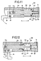
- variable force cylinder device 130 according to a fifth embodiment of the present invention will next be shown in FIGS. 11 and 12.
- the variable force cylinder device 130 comprises a cylinder body 138 having a cylinder chamber 136 made up of a large-bore portion 132 and a small-bore portion 134.
- a piston 140 has a small-diameter portion 142 having a small pressure-receiving area and a large-diameter portion 144 having a large pressure-receiving area.
- a sealing member 146 pressed against the inner wall of the cylinder chamber 136 is mounted on the large-diameter portion 144. Further, a sealing member 148 brought into sliding contact with the outer peripheral surface of the small-diameter portion 142 of the piston 140 is provided inside of the small-bore portion 134 in the cylinder chamber 136.
- variable force cylinder device 130 Operation of the variable force cylinder device 130 according to a fifth embodiment will now be described below.
- a pressurized fluid introduced through a pressurized fluid discharge/intake port 14 is supplied to the small-bore portion 134 so as to act on the pressure-receiving surface of the small-diameter portion 142 of the piston 140, thereby to move the piston 140 in the direction indicated by an arrow A. Since, the pressure-receiving area of the small-diameter portion 142 is small, the force acting on the piston 140 in the direction of termination of its stroke is relatively weak.
- the sealing member 148 provided inside of the small-bore portion 134 can be pressed against the outer peripheral surface of the small-diameter portion 142 of the piston 140 so as to exhibit a sealing effect.
- the sealing member 148 is detached from the outer peripheral surface of the small-diameter portion 142 so that the pressurized fluid introduced through the port 14 acts on the large-diameter portion 144 of the piston 140 as a pressure-receiving surface. Therefore, since the pressure-receiving area is changed from a small one to a large one, the force acting on the piston 140 in the direction of the termination of the piston stroke is relatively strong. Thus, when the piston 140 is situated in the terminal position of its stroke and the arm 28 is rotated the predetermined angle, a relatively strong force is transmitted to the arm 28 so that a workpiece can be reliably clamped.
Landscapes
- Engineering & Computer Science (AREA)
- Mechanical Engineering (AREA)
- General Engineering & Computer Science (AREA)
- Physics & Mathematics (AREA)
- Fluid Mechanics (AREA)
- Actuator (AREA)
- Manipulator (AREA)
- Fluid-Pressure Circuits (AREA)
- Pistons, Piston Rings, And Cylinders (AREA)
Claims (6)
- Dispositif de vérin à force variable, comprenant un piston (60, 140) couplé à une extrémité d'une tige de piston (22) déplacé en va-et-vient par un fluide sous pression dans une chambre de cylindre (56, 136), dans lequel:ledit mécanisme de force variable comprenant:ledit piston (60, 140) comprend une partie de grand diamètre (64, 144) et une partie de petit diamètre (62, 142),ladite chambre de cylindre (56, 136) comprend une partie à gros alésage (52, 132) qui correspond à ladite partie de grand diamètre (64, 144) du piston (60, 140) et une partie à petit alésage (54, 134) qui correspond à ladite partie de petit diamètre (62, 142) du piston (60, 140), etun mécanisme de force variable sert à faire varier la surface utile de réception de pression du piston (60, 140) par une interaction variable du piston (60, 140) et de la chambre de cylindre (56, 136) en fonction des phases de la course du piston,un moyen pour amener le fluide sous pression à agir principalement sur une face d'extrémité de ladite partie de grand diamètre (64, 144) uniquement lorsque ledit piston (60, 144) a parcouru une distance supérieure à la moitié de la longueur totale de la course dudit piston (60, 140),ladite partie de petit diamètre du piston (60) formée comme une barre rectiligne (62, 142) dépassant d'un coté de la partie de grand diamètre (64, 144) disposé à l'opposition de ladite tige de piston (22), dans lequel lesdites parties de petit et de grand diamètre (62, 64) sont disposées dans l'ordre cité dans la direction d'une course descendante du piston (60, 140) au cours de laquelle une face d'extrémité de ladite barre rectiligne de petit diamètre (62, 142) s'éloigne du fond de la partie à petit alésage (54, 134).
- Dispositif de vérin à force variable, comprenant un piston (20) couplé à une extrémité d'une tige de piston (22) déplacé en va-et-vient par un fluide sous pression dans une chambre de cylindre (18), dans lequel:ledit mécanisme de force variable comprenantledit piston (20) comprend une partie de grand diamètre (34) et une partie de petit diamètre (36),ladite chambre de cylindre (18) comprend une partie à gros alésage (30) qui correspond à ladite partie de grand diamètre (34) du piston (20) et une partie à petit alésage (32) qui correspond à ladite partie de petit diamètre (36) du piston (20), etun mécanisme de force variable sert à faire varier la surface utile de réception de pression du piston (20) par une interaction variable du piston (20) et de la chambre de cylindre (18) en fonction des phases de la course du piston,
un moyen pour équilibrer les pressions avant et arrière dudit piston (20) uniquement tant que ledit piston (20) n'a pas parcouru une distance supérieure à la moitié de la longueur totale de la course dudit piston (20), ledit moyen pour équilibrer comprenant un élément formant segment qui est monté autour de ladite partie de gros diamètre (34), dont la périphérie est en contact glissant avec une surface de paroi de ladite partie à gros alésage (30) et qui sert de clapet anti-retour (42) permettant au fluide sous pression de ne passer que dans la direction de ladite course descendante, au cours de laquelle une face descendante, au cours de laquelle une face d'extrémité de ladite partie de gros diamètre (34) s'éloigne du fond de la partie à gros alésage (30). - Dispositif de vérin selon la revendication 2, dans lequel les diamètres desdites parties de grand et de petit diamètre (34, 36) sont disposées dans l'ordre cité dans la direction d'une course descendante du piston (20) au cours de laquelle une face d'extrémité de la partie de grand diamètre (34) s'éloigne du fond de la partie à gros alésage (30), dans lequel le fluide sous pression est introduit dans le fond de ladite partie à gros alésage (30) quand le piston (20) est dans ladite course descendante et est introduit dans le fond de ladite partie à petit alésage (32) quand le piston (20) est dans une course ascendante au cours de laquelle ladite face d'extrémité de la partie de gros diamètre (34) s'approche du fond de la partie à gros alésage (30), et dans lequel ledit mécanisme de force variable comprend une bague d'étanchéité (46) qui est montée autour de ladite partie de petit diamètre (36) et qui sert de bague d'étanchéité uniquement lorsque ladite partie de petit diamètre (36) est placée dans ladite partie à petit alésage (32) pendant la phase finale de ladite course descendante.
- Dispositif de vérin selon la revendication 1, dans lequel le fluide sous pression est introduit dans le fond de ladite partie à petit alésage (54) quand le piston (60) est dans ladite course descendante et dans le fond de ladite partie à gros alésage (52) quand le piston (60) est dans une course ascendante au cours de laquelle ladite face d'extrémité de ladite partie de petit diamètre (62) s'approche dudit fond de la partie à petit alésage (54), et dans lequel ledit mécanisme de force variable comprend un élément cylindrique (66) destiné à recouvrir la totalité de ladite barre rectiligne de manière coulissante et étanche aux fluides, comportant un orifice (70) défini dans son fond et destiné à l'introduction du fluide sous pression dans ledit élément cylindrique (66) depuis ladite partie à petit alésage (54), comportant une partie d'extrémité dans le côté du fond dudit élément cylindrique (66) dont le diamètre extérieur est réduit de sorte que le fluide sous pression fuit dans ladite partie à gros alésage (52) par un espace annulaire formé entre ladite partie d'extrémité et ladite partie à petit alésage (54) pendant la phase finale de ladite course descendante, ladite partie à petit alésage (54) de la chambre de cylindre (56) étant formée comme un trou rectiligne destiné à recevoir la totalité dudit élément cylindrique (66) de manière coulissante et étanche aux fluides jusqu'à ce que ladite phase finale de ladite course descendante soit atteinte, et ladite partie de grand diamètre (64) du piston (60) logée dans ladite partie à gros alésage (52) de la chambre de cylindre (56).
- Dispositif de vérin à force variable, comprenant un piston (110) couplé à une extrémité d'une tige de piston (22) déplacé en va-et-vient par un fluide sous pression dans une chambre de cylindre (106), dans lequel:ledit mécanisme de force variable comprenantledit piston (110) comprend une partie de grand diamètre (114) et une partie de petit diamètre,ladite chambre de cylindre (106) comprend une partie à gros alésage (102) qui correspond à ladite partie de grand diamètre (114) du piston (110) et une partie à petit alésage (104) qui correspond à ladite partie de petit diamètre du piston (110), etun mécanisme de force variable sert à faire varier la surface utile de réception de pression du piston (110) par une interaction variable du piston (110) et de la chambre de cylindre (106) en fonction des phases de la course du piston,la partie restante de ladite tige (118) étant reçue de manière coulissante et étanche aux fluides dans ledit trou borgne (112), etun moyen pour amener le fluide sous pression à agir principalement sur une farce d'extrémité de ladite partie de grand diamètre (114) uniquement tant que ledit piston (110) n'a pas parcouru une distance supérieure à la moitié de la longueur totale de la course dudit piston (110),dans lequel une face de réception de la pression de ladite partie de petit diamètre dudit piston (110) constitue la face de fond d'un trou borgne (112) percé dans dudit piston (110) depuis une face d'extrémité dudit piston (110) sur une profondeur inférieure ou égale à la course dudit piston (110), ladite partie de grand diamètre (114) est située au niveau de ladite face d'extrémité, dans lequel les parties à petit et gros alésage (104, 102) sont disposées dans l'ordre cité dans la direction d'une course descendante du piston (110) au cours de laquelle ladite face d'extrémité du piston (110) s'éloigne du fond de ladite partie à gros alésage (102) à laquelle fait face ladite face d'extrémité, dans lequel ledit fluide sous pression est introduit dans ledit trou borgne (112) par ladite partie à petit alésage (104) et un élément formant tige (118) quand le piston (110) est dans ladite course descendante et est introduit dans ladite partie à gros alésage (102) quand le piston (110) est dans une course ascendante au cours de laquelle ladite face d'extrémité du piston (110) s'approche dudit fond de la partie à gros alésage (102),ledit élément formant tige (118) destiné à coupler de manière coulissante ledit trou borgne (112) et ladite partie à petit alésage (104), présentant un trou traversant (116) destiné à faire que la pression du fluide sous pression agisse sur ladite face de fond du trou borgne (112), et une partie d'extrémité logée dans la partie à petit alésage (104), dont le diamètre extérieur est réduit de sorte que le fluide sous pression fuit dans ladite partie à gros alésage (102) par un espace annulaire formé entre ladite partie d'extrémité et la partie à petit alésage (104) pendant la phase finale de ladite course descendante,une partie dudit élément formant tige (118), dotée de ladite partie d'extrémité, étant reçue de manière coulissante et étanche aux fluides dans ladite partie à petit alésage (104) jusqu'à ce que ladite phase finale de ladite course descendante soit atteinte,
ladite partie de grand diamètre (114) du piston (110) étant logée dans ladite partie à gros alésage (102) de la chambre de cylindre (106). - Dispositif de vérin selon la revendication 1, dans lequel ledit fluide sous pression est introduit dans le fond de ladite partie à petit alésage (134) quand le piston (140) est dans ladite course descendante et est introduit dans le fond de ladite partie à gros alésage (132) quand ie piston (140) est dans une course ascendante au cours de laquelle ladite face d'extrémité de ladite partie de petit diamètre (142) s'approche dudit fond de la partie à petit alésage (134), et dans lequel ledit mécanisme de force variable comprend:ladite barre rectiligne ayant une longueur inférieure ou égale à la course du piston (140), et comprenant une partie d'extrémité dont le diamètre est réduit de sorte que le fluide sous pression fuit dans ladite partie à gros alésage (132) par un espace annulaire formé entre ladite partie d'extrémité et ladite partie à petit alésage (134) pendant la phase finale de ladite course descendante,ladite partie à petit alésage (134) de la chambre de cylindre (136) dans laquelle la totalité de ladite partie de petit diamètre (142) est reçue de manière coulissante et étanche aux fluides jusqu'à ce que ladite phase finale de ladite course descendante soit atteinte, etladite partie de gros diamètre (144) du piston (140) logée dans ladite partie à gros alésage (132) de la chambre de cylindre (136).
Applications Claiming Priority (3)
| Application Number | Priority Date | Filing Date | Title |
|---|---|---|---|
| JP4322013A JP2598210B2 (ja) | 1992-12-01 | 1992-12-01 | シリンダ装置 |
| JP32201392 | 1992-12-01 | ||
| JP322013/92 | 1992-12-01 |
Publications (3)
| Publication Number | Publication Date |
|---|---|
| EP0602425A1 EP0602425A1 (fr) | 1994-06-22 |
| EP0602425B1 EP0602425B1 (fr) | 1997-03-26 |
| EP0602425B2 true EP0602425B2 (fr) | 2001-11-21 |
Family
ID=18138951
Family Applications (1)
| Application Number | Title | Priority Date | Filing Date |
|---|---|---|---|
| EP93118950A Expired - Lifetime EP0602425B2 (fr) | 1992-12-01 | 1993-11-25 | Dispositif de cylindre à force variable |
Country Status (5)
| Country | Link |
|---|---|
| US (1) | US5440968A (fr) |
| EP (1) | EP0602425B2 (fr) |
| JP (1) | JP2598210B2 (fr) |
| KR (1) | KR970009999B1 (fr) |
| DE (1) | DE69309235T3 (fr) |
Families Citing this family (41)
| Publication number | Priority date | Publication date | Assignee | Title |
|---|---|---|---|---|
| US5632606A (en) * | 1993-11-23 | 1997-05-27 | Sarcos Group | Volumetric pump/valve |
| US6007310A (en) * | 1993-11-23 | 1999-12-28 | Sarcos, Lc | Volumetric pump with sterility seal |
| US5931647A (en) * | 1993-11-23 | 1999-08-03 | Sarcos, Inc. | Volumetric pump with bi-directional piston seal |
| US5826562A (en) | 1994-07-29 | 1998-10-27 | Caterpillar Inc. | Piston and barrell assembly with stepped top and hydraulically-actuated fuel injector utilizing same |
| FR2746889B1 (fr) * | 1996-03-29 | 1998-06-05 | Asco Joucomatic Sa | Joint d'etancheite, notamment pour verin pneumatique ou hydraulique |
| DE19706059C2 (de) * | 1997-02-04 | 1998-12-03 | Mannesmann Ag | Schieberventil |
| US6035634A (en) * | 1999-02-09 | 2000-03-14 | Latch-Tool Development Co. Llc | Compact, resistance regulated, multiple output hydraulic tool and seal valve arrangement |
| NO312185B1 (no) * | 2000-01-05 | 2002-04-08 | Kongsberg Automotive Asa | Trykkfluidavgivende innretning |
| FR2831598A1 (fr) * | 2001-10-25 | 2003-05-02 | Mdi Motor Dev Internat | Groupe motocompresseur-motoalternateur a injection d'air comprime additionnel fonctionnant en mono et pluri energies |
| RU2219384C2 (ru) * | 2001-12-25 | 2003-12-20 | Закрытое акционерное общество "Национальная компания Уралтерминалмаш" | Гидроцилиндр |
| RU2219382C2 (ru) * | 2001-12-25 | 2003-12-20 | Закрытое акционерное общество "Национальная компания Уралтерминалмаш" | Гидроцилиндр |
| RU2219386C2 (ru) * | 2001-12-25 | 2003-12-20 | Закрытое акционерное общество "Национальная компания Уралтерминалмаш" | Гидроцилиндр |
| RU2219387C2 (ru) * | 2001-12-25 | 2003-12-20 | Закрытое акционерное общество "Национальная компания Уралтерминалмаш" | Гидроцилиндр |
| RU2219383C2 (ru) * | 2001-12-25 | 2003-12-20 | Закрытое акционерное общество "Национальная компания Уралтерминалмаш" | Гидроцилиндр |
| RU2219381C2 (ru) * | 2001-12-25 | 2003-12-20 | Закрытое акционерное общество "Национальная компания Уралтерминалмаш" | Гидроцилиндр |
| US7032574B2 (en) * | 2003-03-24 | 2006-04-25 | Sturman Industries, Inc. | Multi-stage intensifiers adapted for pressurized fluid injectors |
| US7815176B2 (en) | 2003-09-11 | 2010-10-19 | Phd, Inc. | Lock mechanism for pin clamp assembly |
| US7516948B2 (en) | 2004-04-02 | 2009-04-14 | Phd, Inc. | Pin clamp accessories |
| US7182326B2 (en) * | 2004-04-02 | 2007-02-27 | Phd, Inc. | Pin clamp |
| DE102004022723A1 (de) | 2004-05-07 | 2005-11-24 | Dr.Ing.H.C. F. Porsche Ag | Hydraulischer Linearantrieb, insbesondere hydraulischer Getriebeaktuator |
| DE102004022722A1 (de) * | 2004-05-07 | 2005-11-24 | Dr.Ing.H.C. F. Porsche Ag | Hydraulischer Getriebeaktuator |
| US7448607B2 (en) * | 2004-12-15 | 2008-11-11 | Phd, Inc. | Pin clamp assembly |
| US7568633B2 (en) * | 2005-01-13 | 2009-08-04 | Sturman Digital Systems, Llc | Digital fuel injector, injection and hydraulic valve actuation module and engine and high pressure pump methods and apparatus |
| RU2286484C1 (ru) * | 2005-04-11 | 2006-10-27 | Общество с ограниченной ответственностью "Фирма СПРУТ" | Гидравлический цилиндр |
| WO2008141237A1 (fr) * | 2007-05-09 | 2008-11-20 | Sturman Digital Systems, Llc | Injecteurs-multiplicateurs de pression multiples avec commande d'aiguille positive et procédés d'injection |
| US8413970B2 (en) | 2007-06-19 | 2013-04-09 | Phd, Inc. | Pin clamp assembly |
| CA2665708C (fr) * | 2007-06-26 | 2010-08-24 | Starcyl Canada Inc. | Ensemble vanne pour un dispositif de regulation d'ecoulement |
| EP2303505B1 (fr) * | 2008-06-18 | 2019-02-27 | PHD, Inc. | Pince à broche à enlèvement |
| US20100012745A1 (en) | 2008-07-15 | 2010-01-21 | Sturman Digital Systems, Llc | Fuel Injectors with Intensified Fuel Storage and Methods of Operating an Engine Therewith |
| RU2447327C2 (ru) * | 2010-03-15 | 2012-04-10 | Государственное образовательное учреждение высшего профессионального образования "Братский государственный университет" | Гидроцилиндр |
| DE102011051400B3 (de) * | 2011-06-28 | 2012-06-06 | Parker Hannifin Gmbh | Pneumatikzylinder mit selbstjustierender Endlagendämpfung |
| DE102011112553A1 (de) * | 2011-09-06 | 2013-03-07 | Knorr-Bremse Systeme für Schienenfahrzeuge GmbH | Steuerventil für selbsttätige Druckluftbremsen mit Gleitführungsmitteln |
| US9003951B2 (en) | 2011-10-05 | 2015-04-14 | Caterpillar Inc. | Hydraulic system with bi-directional regeneration |
| US9181890B2 (en) | 2012-11-19 | 2015-11-10 | Sturman Digital Systems, Llc | Methods of operation of fuel injectors with intensified fuel storage |
| GB201314885D0 (en) | 2013-08-20 | 2013-10-02 | 3M Innovative Properties Co | Personal respiratory protection device |
| GB201314884D0 (en) | 2013-08-20 | 2013-10-02 | 3M Innovative Properties Co | Personal respiratory protection device |
| GB201314886D0 (en) | 2013-08-20 | 2013-10-02 | 3M Innovative Properties Co | Personal respiratory protection device |
| GB201314887D0 (en) | 2013-08-20 | 2013-10-02 | 3M Innovative Properties Co | Personal respiratory protection device |
| WO2016010656A1 (fr) | 2014-07-14 | 2016-01-21 | Ridge Tool Company | Outils hydrauliques à avance rapide |
| DE102016102852A1 (de) | 2016-02-18 | 2017-08-24 | Festo Ag & Co. Kg | Dichtungssystem für ein bewegliches Element |
| CN108799239A (zh) * | 2018-06-29 | 2018-11-13 | 苏州舍勒智能科技有限公司 | 一种直线伸缩式垂直旋转气缸 |
Citations (5)
| Publication number | Priority date | Publication date | Assignee | Title |
|---|---|---|---|---|
| US1241691A (en) † | 1915-07-13 | 1917-10-02 | Hoe & Co R | Hydraulic press. |
| US2293334A (en) † | 1939-05-05 | 1942-08-18 | Hydraulic Dev Corp Inc | Check and unloading valve structure |
| DE2813694A1 (de) † | 1978-03-30 | 1979-10-04 | Tuenkers Maschinenbau Gmbh | Pneumatische oder hydraulische kniehebelspannvorrichtung mit zweistufendruckzylinder |
| US4173171A (en) † | 1976-07-06 | 1979-11-06 | Firma Dieter Haubold Industrielle Nagelgerate | Working process of a pneumatic operated ramming tool |
| DE3615269A1 (de) † | 1986-05-06 | 1987-11-19 | Festo Kg | Positioniervorrichtung |
Family Cites Families (15)
| Publication number | Priority date | Publication date | Assignee | Title |
|---|---|---|---|---|
| DE215831C (fr) * | ||||
| US2574299A (en) * | 1947-12-31 | 1951-11-06 | Vance C Sterrett | Piston construction |
| NL6902037A (fr) * | 1969-02-10 | 1970-08-12 | ||
| FR2138342B1 (fr) * | 1971-05-24 | 1974-03-08 | Poclain Sa | |
| US3842717A (en) * | 1973-06-21 | 1974-10-22 | Atwood & Morrill Co Inc | Piston seal |
| DE2344657A1 (de) * | 1973-09-05 | 1975-03-13 | Bbc Brown Boveri & Cie | Hydraulikzylinder mit einem innerhalb des zylinders bewegbaren kolben |
| JPS52100675A (en) * | 1976-02-19 | 1977-08-23 | Japan Steel Works Ltd:The | High speed forging hammer press |
| JPS55142101A (en) * | 1979-04-23 | 1980-11-06 | Masuo Shiaku | Output booster for gas reciprocating expansion cylinder |
| IN150181B (fr) * | 1979-06-26 | 1982-08-07 | Lucas Industries Ltd | |
| JPS57177409A (en) * | 1981-04-22 | 1982-11-01 | Hino Motors Ltd | Hydraulic cylinder for cab tilt |
| GB2139318B (en) * | 1983-05-04 | 1986-07-23 | Dowty Seals Ltd | Piston/cylinder seal construction |
| DD215831A1 (de) * | 1983-06-02 | 1984-11-21 | Bernau Schichtpressstoff | Arbeitszylinder mit innenanschlag |
| JPS61167704A (ja) * | 1985-01-19 | 1986-07-29 | Hikoma Seisakusho Kk | 作動力変更可能な油圧シリンダー |
| JPS63300840A (ja) * | 1987-05-30 | 1988-12-08 | Okuma Mach Works Ltd | クランプシリンダ |
| US5167419A (en) * | 1991-10-22 | 1992-12-01 | Freudenberg-Nok General Partnership | Fluid seal with integral check valve |
-
1992
- 1992-12-01 JP JP4322013A patent/JP2598210B2/ja not_active Expired - Fee Related
-
1993
- 1993-11-25 EP EP93118950A patent/EP0602425B2/fr not_active Expired - Lifetime
- 1993-11-25 DE DE69309235T patent/DE69309235T3/de not_active Expired - Lifetime
- 1993-11-30 US US08/159,293 patent/US5440968A/en not_active Expired - Lifetime
- 1993-12-01 KR KR1019930026048A patent/KR970009999B1/ko not_active Expired - Lifetime
Patent Citations (5)
| Publication number | Priority date | Publication date | Assignee | Title |
|---|---|---|---|---|
| US1241691A (en) † | 1915-07-13 | 1917-10-02 | Hoe & Co R | Hydraulic press. |
| US2293334A (en) † | 1939-05-05 | 1942-08-18 | Hydraulic Dev Corp Inc | Check and unloading valve structure |
| US4173171A (en) † | 1976-07-06 | 1979-11-06 | Firma Dieter Haubold Industrielle Nagelgerate | Working process of a pneumatic operated ramming tool |
| DE2813694A1 (de) † | 1978-03-30 | 1979-10-04 | Tuenkers Maschinenbau Gmbh | Pneumatische oder hydraulische kniehebelspannvorrichtung mit zweistufendruckzylinder |
| DE3615269A1 (de) † | 1986-05-06 | 1987-11-19 | Festo Kg | Positioniervorrichtung |
Also Published As
| Publication number | Publication date |
|---|---|
| JP2598210B2 (ja) | 1997-04-09 |
| JPH06173908A (ja) | 1994-06-21 |
| EP0602425A1 (fr) | 1994-06-22 |
| US5440968A (en) | 1995-08-15 |
| DE69309235D1 (de) | 1997-04-30 |
| DE69309235T2 (de) | 1997-10-09 |
| EP0602425B1 (fr) | 1997-03-26 |
| DE69309235T3 (de) | 2002-08-14 |
| KR940015331A (ko) | 1994-07-20 |
| KR970009999B1 (ko) | 1997-06-20 |
Similar Documents
| Publication | Publication Date | Title |
|---|---|---|
| EP0602425B2 (fr) | Dispositif de cylindre à force variable | |
| US3981479A (en) | Check valve | |
| US4104008A (en) | Pump having fluid-actuated motor controlled by fluid-actuated distributor | |
| KR100559101B1 (ko) | 매체분배기 | |
| EP0381188B1 (fr) | Ressort sous gaz blocable hydrauliquement | |
| US4522373A (en) | Valve detent | |
| US5170691A (en) | Fluid pressure amplifier | |
| GB2310908A (en) | Piston-cylinder locking means | |
| FI70302C (fi) | Hydraulisk styrventil | |
| JPH02218873A (ja) | 圧縮空気で作動されるポンプ装置 | |
| US10895269B2 (en) | Double acting hydraulic pressure intensifier | |
| EP1384004B1 (fr) | Combinaison d'une chambre et d'un piston, pompe, moteur, amortisseur et transducteur integrant ladite combinaison | |
| AU2002308385A1 (en) | A combination of a chamber and a piston, a pump, a motor, a shock absorber and a transducer incorporating the combination | |
| US4291718A (en) | Pressure valve | |
| EP3896293B1 (fr) | Cylindre de pression de fluide | |
| US6019026A (en) | Self-centering motor | |
| CA2118971A1 (fr) | Clapet de retenue interne | |
| US3557663A (en) | Hydraulic drive system for injection molding machines | |
| GB2072886A (en) | Servo assembly | |
| KR960008272B1 (ko) | 속도제어기 | |
| JP2645943B2 (ja) | 増圧型流体圧シリンダ | |
| US5188014A (en) | Hydraulic cylinder with pressure transmission | |
| US4757835A (en) | Change-over valve for hydraulic walking mine-roof supports | |
| PL165086B1 (pl) | dzony przewód osiowy .FIG 1 PL | |
| US12104623B2 (en) | Three-position pneumatic or hydraulic power cylinder |
Legal Events
| Date | Code | Title | Description |
|---|---|---|---|
| PUAI | Public reference made under article 153(3) epc to a published international application that has entered the european phase |
Free format text: ORIGINAL CODE: 0009012 |
|
| 17P | Request for examination filed |
Effective date: 19931208 |
|
| AK | Designated contracting states |
Kind code of ref document: A1 Designated state(s): DE FR GB IT |
|
| 17Q | First examination report despatched |
Effective date: 19940805 |
|
| GRAG | Despatch of communication of intention to grant |
Free format text: ORIGINAL CODE: EPIDOS AGRA |
|
| GRAH | Despatch of communication of intention to grant a patent |
Free format text: ORIGINAL CODE: EPIDOS IGRA |
|
| GRAH | Despatch of communication of intention to grant a patent |
Free format text: ORIGINAL CODE: EPIDOS IGRA |
|
| GRAA | (expected) grant |
Free format text: ORIGINAL CODE: 0009210 |
|
| AK | Designated contracting states |
Kind code of ref document: B1 Designated state(s): DE FR GB IT |
|
| REF | Corresponds to: |
Ref document number: 69309235 Country of ref document: DE Date of ref document: 19970430 |
|
| ET | Fr: translation filed | ||
| PLBQ | Unpublished change to opponent data |
Free format text: ORIGINAL CODE: EPIDOS OPPO |
|
| PLBI | Opposition filed |
Free format text: ORIGINAL CODE: 0009260 |
|
| 26 | Opposition filed |
Opponent name: FESTO AG & CO Effective date: 19971205 |
|
| PLBF | Reply of patent proprietor to notice(s) of opposition |
Free format text: ORIGINAL CODE: EPIDOS OBSO |
|
| PLBF | Reply of patent proprietor to notice(s) of opposition |
Free format text: ORIGINAL CODE: EPIDOS OBSO |
|
| PLBF | Reply of patent proprietor to notice(s) of opposition |
Free format text: ORIGINAL CODE: EPIDOS OBSO |
|
| PLAW | Interlocutory decision in opposition |
Free format text: ORIGINAL CODE: EPIDOS IDOP |
|
| PLAW | Interlocutory decision in opposition |
Free format text: ORIGINAL CODE: EPIDOS IDOP |
|
| PUAH | Patent maintained in amended form |
Free format text: ORIGINAL CODE: 0009272 |
|
| STAA | Information on the status of an ep patent application or granted ep patent |
Free format text: STATUS: PATENT MAINTAINED AS AMENDED |
|
| PGFP | Annual fee paid to national office [announced via postgrant information from national office to epo] |
Ref country code: FR Payment date: 20011119 Year of fee payment: 9 |
|
| 27A | Patent maintained in amended form |
Effective date: 20011121 |
|
| AK | Designated contracting states |
Kind code of ref document: B2 Designated state(s): DE FR GB IT |
|
| REG | Reference to a national code |
Ref country code: GB Ref legal event code: IF02 |
|
| ET3 | Fr: translation filed ** decision concerning opposition | ||
| PG25 | Lapsed in a contracting state [announced via postgrant information from national office to epo] |
Ref country code: FR Free format text: LAPSE BECAUSE OF NON-PAYMENT OF DUE FEES Effective date: 20030731 |
|
| REG | Reference to a national code |
Ref country code: FR Ref legal event code: ST |
|
| PG25 | Lapsed in a contracting state [announced via postgrant information from national office to epo] |
Ref country code: IT Free format text: LAPSE BECAUSE OF NON-PAYMENT OF DUE FEES Effective date: 20051125 |
|
| PGFP | Annual fee paid to national office [announced via postgrant information from national office to epo] |
Ref country code: DE Payment date: 20121121 Year of fee payment: 20 |
|
| PGFP | Annual fee paid to national office [announced via postgrant information from national office to epo] |
Ref country code: GB Payment date: 20121120 Year of fee payment: 20 |
|
| REG | Reference to a national code |
Ref country code: DE Ref legal event code: R071 Ref document number: 69309235 Country of ref document: DE |
|
| REG | Reference to a national code |
Ref country code: GB Ref legal event code: PE20 Expiry date: 20131124 |
|
| PG25 | Lapsed in a contracting state [announced via postgrant information from national office to epo] |
Ref country code: GB Free format text: LAPSE BECAUSE OF EXPIRATION OF PROTECTION Effective date: 20131124 Ref country code: DE Free format text: LAPSE BECAUSE OF EXPIRATION OF PROTECTION Effective date: 20131126 |