EP0601427A2 - Instrument endoscopique - Google Patents
Instrument endoscopique Download PDFInfo
- Publication number
- EP0601427A2 EP0601427A2 EP93119171A EP93119171A EP0601427A2 EP 0601427 A2 EP0601427 A2 EP 0601427A2 EP 93119171 A EP93119171 A EP 93119171A EP 93119171 A EP93119171 A EP 93119171A EP 0601427 A2 EP0601427 A2 EP 0601427A2
- Authority
- EP
- European Patent Office
- Prior art keywords
- shaft
- instrument
- shaped
- cross
- instrument according
- Prior art date
- Legal status (The legal status is an assumption and is not a legal conclusion. Google has not performed a legal analysis and makes no representation as to the accuracy of the status listed.)
- Withdrawn
Links
Images

Classifications
-
- A—HUMAN NECESSITIES
- A61—MEDICAL OR VETERINARY SCIENCE; HYGIENE
- A61B—DIAGNOSIS; SURGERY; IDENTIFICATION
- A61B1/00—Instruments for performing medical examinations of the interior of cavities or tubes of the body by visual or photographical inspection, e.g. endoscopes; Illuminating arrangements therefor
- A61B1/00163—Optical arrangements
- A61B1/00174—Optical arrangements characterised by the viewing angles
- A61B1/00181—Optical arrangements characterised by the viewing angles for multiple fixed viewing angles
-
- A—HUMAN NECESSITIES
- A61—MEDICAL OR VETERINARY SCIENCE; HYGIENE
- A61B—DIAGNOSIS; SURGERY; IDENTIFICATION
- A61B1/00—Instruments for performing medical examinations of the interior of cavities or tubes of the body by visual or photographical inspection, e.g. endoscopes; Illuminating arrangements therefor
- A61B1/012—Instruments for performing medical examinations of the interior of cavities or tubes of the body by visual or photographical inspection, e.g. endoscopes; Illuminating arrangements therefor characterised by internal passages or accessories therefor
- A61B1/015—Control of fluid supply or evacuation
-
- A—HUMAN NECESSITIES
- A61—MEDICAL OR VETERINARY SCIENCE; HYGIENE
- A61B—DIAGNOSIS; SURGERY; IDENTIFICATION
- A61B1/00—Instruments for performing medical examinations of the interior of cavities or tubes of the body by visual or photographical inspection, e.g. endoscopes; Illuminating arrangements therefor
- A61B1/012—Instruments for performing medical examinations of the interior of cavities or tubes of the body by visual or photographical inspection, e.g. endoscopes; Illuminating arrangements therefor characterised by internal passages or accessories therefor
- A61B1/018—Instruments for performing medical examinations of the interior of cavities or tubes of the body by visual or photographical inspection, e.g. endoscopes; Illuminating arrangements therefor characterised by internal passages or accessories therefor for receiving instruments
-
- A—HUMAN NECESSITIES
- A61—MEDICAL OR VETERINARY SCIENCE; HYGIENE
- A61B—DIAGNOSIS; SURGERY; IDENTIFICATION
- A61B1/00—Instruments for performing medical examinations of the interior of cavities or tubes of the body by visual or photographical inspection, e.g. endoscopes; Illuminating arrangements therefor
- A61B1/12—Instruments for performing medical examinations of the interior of cavities or tubes of the body by visual or photographical inspection, e.g. endoscopes; Illuminating arrangements therefor with cooling or rinsing arrangements
Definitions
- the invention relates to an endoscopic instrument with the features specified in the preamble of claim 1.
- the present invention is based on a pan-hysteroscope system, as is offered and sold by Richard Wolf GmbH in Knittlingen, for example.
- viewing optics and a treatment instrument are arranged side by side within the shaft. Since the distal shaft end ends in a channel-shaped part, both the optics and the instrument are protected on one side while they are open on the other, that is to say on the open side of the channel-shaped part, in such a way that, for example, the instrument is bent in this direction or in its axial direction can be moved.
- flexible pliers, laser fibers or the like can be used as the instrument.
- Such an instrument is particularly intended for endoscopic examination and treatment of the uterus.
- Silicone inlays have been used for a long time, particularly for breast reconstruction. With such silicone inserts, the implant is sometimes encapsulated. Damage to the implant cannot be ruled out. In such cases it has been so far It is usual to check the implant by surgery, to dissolve the encapsulation or, if necessary, to replace the implant. Proceeding from this, the present invention is based on the object of designing an endoscopic instrument in such a way that both the visual inspection of the implant and the release of an encapsulation and, if appropriate, further interventions, in particular in the area of the female breast, are carried out with sufficient security endoscopically and thus minimally invasively can.
- this is achieved on the basis of the prior art mentioned above (hysteroscope) in that a recess is provided in the distal, tapered end part of the shaft for forming an additional viewing window for the viewing optics.
- the instrument according to the invention enables endoscopic interventions in the area of the female breast, in particular in connection with the inspection and release of an encapsulation of the implant.
- an instrument can also be used for other interventions, such as tissue extraction or for other diagnostic purposes.
- the surgeon inserts the instrument according to the invention in the area of the nipple and can then first of all inspect the implant without an open operation and, if necessary, also open an encapsulation.
- the protection of the implant must be given special attention for all such endoscopic interventions.
- the channel-shaped end part of the shaft is provided, which shields both the viewing optics and the treatment instrument, for example a laser fiber, to one side. In any case, contact between the laser fiber on the one hand and the implant on the other must be avoided.
- the beak-shaped design of the distal shaft end alone is not sufficient, because it is particularly the case with the Opening of the encapsulation is necessary to always keep an eye on the implant.
- the additional viewing window is provided in the channel-shaped end part of the shaft end. The operator can thus always observe the implant while the encapsulation is being opened.
- the trough-shaped design of the shaft end also ensures that the treatment instrument can only be moved and used in its axial direction or in the direction facing away from the implant, i.e. towards the open side of the channel profile, and that the instrument itself can be used on the implant slides along.
- a laser fiber is preferably used as the treatment instrument, but an HF probe or a mechanical instrument, for example a pair of pliers or a combination instrument, can also be used.
- a laser fiber which is fed, for example, by means of a neodymium-YAG laser, has proven particularly suitable for the aforementioned opening of the capsule. It is understood that tissue removal or other interventions can also be carried out with the instrument according to the invention.
- the instrument preferably has an essentially oval cross section, the channel-shaped end part being designed and arranged with respect to the remaining shaft cross section such that it includes a long semi-axis of the cross section oval.
- the oval cross-sectional shape as such initially offers the advantage of a smaller circumference and thus a lower load on the engagement opening compared to a round cross-section of the same diameter.
- the viewing optics and treatment instrument can then be in this cross-sectional oval so that they are arranged side by side so that the viewing optics are in direct contact with the shaft part that runs out to the channel-shaped end part, so that on the one hand a clear view through the additional viewing window in this end part and on the other hand a clear view of the treatment instrument and the tissue site treated by it ensure is.
- the distal end of the instrument is rounded as far as possible in order to enable the smoothest possible and injury-free sliding within the body.
- the trough-shaped end part of the shaft is preferably additionally provided with a bevel on its distal end face, in order in this way to enable easier advancement in the axial direction inside the body, which is further supported by the irrigation liquid supplied.
- the groove-shaped end part of the shaft does not extend only by a circumferential angle of approximately 180 °, as is usual in hysteroscopes, but also extends to approximately 200 ° or more, since then the distal ends of Viewing optics and treatment instrument are even better protected and injury to the implant can be largely excluded. It has proven particularly useful if the channel profile of the distal shaft end part is not symmetrical, but rather a wall is extended to one side of the long axis of the cross-sectional oval. The recess for forming the additional viewing window is then preferably located in this part of the wall. With such an arrangement, not only the implant itself but also the position of the implant in relation to the encapsulation can be checked through the additional viewing window during the opening of the capsule.
- the recess has an approximately oval contour in plan view, since on the one hand a sufficiently large opening can be realized and the risk of injury can be kept low.
- the beveling of the distal end of the shaft wall in the region opposite the channel-shaped end part also serves to further reduce the risk of injury.
- an approximately D-shaped tube inside the shaft into which the viewing optics can be inserted and in which it can then be fixed.
- the treatment instrument in particular if it is a laser fiber, a further tube for guiding this fiber can be provided, which rests within the shaft on the flat side of the tube with a D-shaped cross section. If this tube is arranged off-center, there is still space within the shaft for inserting another instrument.
- a guide for this additional instrument is provided within the distal shaft end, in the form of a wedge such that this additional instrument exits from the shaft end of the laser optical fiber is deflected away.
- suction, rinsing or other channels and / or possibly also pipes can be provided within the shaft.
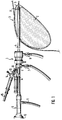
- FIG. 1 shows the instrument 1 according to the invention as it is used to open an encapsulated implant 2 within a female breast 3.
- the breast 3 is shown in section.
- the shaft 4 of the instrument is inserted through an incision in the area of the nipple.
- the capsule to be opened and surrounding the implant 2 is identified by 5.
- the basic structure of the instrument 1 corresponds to a hysteroscope.
- a flushing connection 7 and a suction connection 8 are provided, via which liquid can be guided to the distal end of the instrument and can also be discharged again.
- a central channel for introducing and fixing a viewing optics 9 is provided, the eyepiece 10 thereof and lighting connector 11 can be seen in Figure 1.
- two instrument channels 12 and 13 are led out obliquely at the proximal end 6 of the shaft, each of which can be shut off via a cock 14.
- a laser fiber 15 - this is a light guide for applying laser light - is introduced within the instrument channel 13, the distal end of which lies at the distal end of the shaft and is used for the actual severing.
- the structure within the tubular shaft 4 results in particular from the cross-sectional illustration in FIG. 3.
- the shaft 4 itself has an essentially oval cross-section, in which a tube 16 with a D-shaped cross section for receiving and fixing the viewing optics 9 is arranged.
- the D-shaped tube 16 is located on the side of the shaft 4 on which it runs out distally to a channel-shaped end part 17 and extends over more than half of the shaft cross section, as can be seen from FIG. 3.
- the instrument channel 12 for the laser fiber 15 is formed in the region of the shaft 4 by a tube 18 located therein, which has a circular cross section and is arranged on one side of a long semiaxis 19 of the oval shaft cross section, specifically on the flat side of the D-shaped tube 16
- the tube 18 ends on the distal side in the region of the trough-shaped end part 17, but can also end shortly before, in order to allow the end of the laser fiber a certain elastic deformation, in order thereby to protect the fiber from breaking.
- the instrument channel 12 is not formed separately within the shaft 4, but is delimited by the shaft 4 itself, the flat part of the D-shaped tube 16 and one side of the tube 18.
- a wedge-shaped guide 20 is arranged near the distal shaft end within the shaft 4, which ensures that an instrument inserted into this channel 12 is deflected by the laser fiber 15 when it emerges from the distal shaft end. These Guide 20 is therefore provided in order to avoid a collision between laser fibers and thus possible damage to the laser fibers by this instrument.
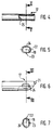
- the formation of the distal end of the shaft 4 as such can be seen in FIGS. 4 to 7.
- the trough-shaped end part 17 projecting beyond the tubular full cross-section is beveled at the front at its distal front end 21, as shown in FIG. 6, in order, for example, to make it easier to guide the instrument between capsule 6 and implant 2.
- the trough-shaped end part 17 is asymmetrical in its cross-sectional profile with respect to the long axis 22 of the shaft cross section.
- the channel profile includes the long semi-axis 19, extends to one side of this semi-axis 17 up to the short axis 23 of the shaft cross-section, while on the other side it clearly projects beyond a wall such that the channel profile as a whole extends over a circumferential angle of approximately 200 ° of the rest Shaft cross section extends. Depending on the requirements, the channel profile can also extend over a larger circumferential angle.
- This channel-shaped end part 17 protects in particular the implant from inadvertent collision with and thus against damage from the distal end of the laser fiber 15 and also from the distal end of the viewing optics 9.
- An additional viewing window 24 is therefore provided in the trough-shaped end part 17 of the shaft 4.
- This window 24 is formed by an approximately oval recess in the shaft wall in plan view, as can be seen from FIG. 6.
- the long axis of this Ovals lies in the axial direction of the instrument.
- the window 24 is provided in the flat side of the channel-shaped end part 17 which projects beyond the short axis 23, but it can also be provided in the bottom of the channel profile, if appropriate.
- the embodiment described above has proven to be particularly advantageous for opening the encapsulation, that is to say for severing the encapsulation, since the implant 2 with respect to the capsule 5 is protected with the side viewing window 24 with the safe protection of the shaft 4, in particular the channel-shaped end part 17 can be observed during processing. As usual, the processing point itself is controlled by the viewing optics 9.
- an additional bevel 25 is provided in the region of the distal end of the shaft, specifically on the end face opposite the channel-shaped end part 17, where the shaft 4 merges into the channel-shaped part 17 .
- This bevel 25 of the end face is shown in Figure 4.
Landscapes
- Health & Medical Sciences (AREA)
- Life Sciences & Earth Sciences (AREA)
- Surgery (AREA)
- Nuclear Medicine, Radiotherapy & Molecular Imaging (AREA)
- Biomedical Technology (AREA)
- Optics & Photonics (AREA)
- Pathology (AREA)
- Radiology & Medical Imaging (AREA)
- Biophysics (AREA)
- Engineering & Computer Science (AREA)
- Physics & Mathematics (AREA)
- Heart & Thoracic Surgery (AREA)
- Medical Informatics (AREA)
- Molecular Biology (AREA)
- Animal Behavior & Ethology (AREA)
- General Health & Medical Sciences (AREA)
- Public Health (AREA)
- Veterinary Medicine (AREA)
- Endoscopes (AREA)
Applications Claiming Priority (2)
| Application Number | Priority Date | Filing Date | Title |
|---|---|---|---|
| DE4241643 | 1992-12-02 | ||
| DE4241643 | 1992-12-02 |
Publications (2)
| Publication Number | Publication Date |
|---|---|
| EP0601427A2 true EP0601427A2 (fr) | 1994-06-15 |
| EP0601427A3 EP0601427A3 (fr) | 1997-08-20 |
Family
ID=6474911
Family Applications (1)
| Application Number | Title | Priority Date | Filing Date |
|---|---|---|---|
| EP93119171A Withdrawn EP0601427A3 (fr) | 1992-12-02 | 1993-11-29 | Instrument endoscopique. |
Country Status (3)
| Country | Link |
|---|---|
| US (1) | US5421323A (fr) |
| EP (1) | EP0601427A3 (fr) |
| CA (1) | CA2110469A1 (fr) |
Families Citing this family (22)
| Publication number | Priority date | Publication date | Assignee | Title |
|---|---|---|---|---|
| US5797960A (en) | 1993-02-22 | 1998-08-25 | Stevens; John H. | Method and apparatus for thoracoscopic intracardiac procedures |
| US6346074B1 (en) | 1993-02-22 | 2002-02-12 | Heartport, Inc. | Devices for less invasive intracardiac interventions |
| AU3075895A (en) * | 1994-07-07 | 1996-02-09 | Ueth & Haug Gmbh | Endoscope |
| GB2339539B (en) * | 1995-10-16 | 2000-04-19 | Precision Optics Corp | Medical visualization device |
| US5951497A (en) | 1996-09-03 | 1999-09-14 | Clinical Innovation Associates, Inc. | Pressure catheter device with enhanced positioning features |
| US6629630B2 (en) * | 1998-06-19 | 2003-10-07 | Scimed Life Systems, Inc. | Non-circular resection device and endoscope |
| US20020068929A1 (en) * | 2000-10-24 | 2002-06-06 | Roni Zvuloni | Apparatus and method for compressing a gas, and cryosurgery system and method utilizing same |
| US6706037B2 (en) * | 2000-10-24 | 2004-03-16 | Galil Medical Ltd. | Multiple cryoprobe apparatus and method |
| US20080045934A1 (en) * | 2000-10-24 | 2008-02-21 | Galil Medical Ltd. | Device and method for coordinated insertion of a plurality of cryoprobes |
| US20070088247A1 (en) * | 2000-10-24 | 2007-04-19 | Galil Medical Ltd. | Apparatus and method for thermal ablation of uterine fibroids |
| US20030130649A1 (en) * | 2000-12-15 | 2003-07-10 | Murray Steven C. | Method and system for treatment of benign prostatic hypertrophy (BPH) |
| US6986764B2 (en) | 2000-12-15 | 2006-01-17 | Laserscope | Method and system for photoselective vaporization of the prostate, and other tissue |
| JP2002338688A (ja) * | 2001-05-15 | 2002-11-27 | Sumitomo Chem Co Ltd | 精ポリエーテルスルホンの製造方法 |
| US20080051776A1 (en) * | 2001-05-21 | 2008-02-28 | Galil Medical Ltd. | Thin uninsulated cryoprobe and insulating probe introducer |
| US20080051774A1 (en) * | 2001-05-21 | 2008-02-28 | Galil Medical Ltd. | Device and method for coordinated insertion of a plurality of cryoprobes |
| JP4768154B2 (ja) * | 2001-06-29 | 2011-09-07 | テルモ株式会社 | 医療用エネルギー照射装置 |
| JP2005518255A (ja) * | 2002-02-22 | 2005-06-23 | レーザースコープ | 婦人科治療用の光選択性気化療法およびそのシステム |
| US8007847B2 (en) * | 2004-01-13 | 2011-08-30 | Eytan Biderman | Feeding formula appliance |
| JP2009524469A (ja) * | 2006-01-26 | 2009-07-02 | ガリル メディカル リミテッド | 複数の冷凍プローブの調和された挿入のための装置及び方法 |
| US20080287940A1 (en) * | 2007-05-14 | 2008-11-20 | Hunter Lowell D | Fiber Pole Tip |
| US8419718B2 (en) * | 2007-05-15 | 2013-04-16 | Ams Research Corporation | Laser handle and fiber guard |
| DE102009015392A1 (de) * | 2009-03-20 | 2010-09-23 | Karl Storz Gmbh & Co. Kg | Medizinisches Instrument, insbesondere Hysteroskop |
Citations (6)
| Publication number | Priority date | Publication date | Assignee | Title |
|---|---|---|---|---|
| US3299883A (en) * | 1963-11-08 | 1967-01-24 | Engelhard Hanovia Inc | Gynecologic instrument |
| DE2327920A1 (de) * | 1973-06-01 | 1974-12-19 | Olympus Optical Co | Endoskop |
| DE3441029A1 (de) * | 1983-11-11 | 1985-05-23 | Fuji Photo Optical Co., Ltd., Omiya, Saitama | Endoskop |
| DE3637789A1 (de) * | 1985-11-13 | 1987-05-21 | Olympus Optical Co | Endoskop |
| DE3716401A1 (de) * | 1986-05-15 | 1987-11-19 | Olympus Optical Co | Adapter fuer einen endoskopkopf |
| US4867138A (en) * | 1987-05-13 | 1989-09-19 | Olympus Optical Co., Ltd. | Rigid electronic endoscope |
Family Cites Families (12)
| Publication number | Priority date | Publication date | Assignee | Title |
|---|---|---|---|---|
| US879224A (en) * | 1906-08-28 | 1908-02-18 | Reinhold H Wappler | Cystoscope. |
| US2018335A (en) * | 1933-08-16 | 1935-10-22 | Wappler Frederick Charles | Endoscopic instrument |
| US2112056A (en) * | 1934-09-19 | 1938-03-22 | Wappler Frederick Charles | Blunted endoscopic instrument |
| DE702374C (de) * | 1939-04-13 | 1941-02-06 | Georg Wolf G M B H | Koerperhoehlenuntersuchungsgeraet |
| US2487498A (en) * | 1946-05-31 | 1949-11-08 | American Cystoscope Makers Inc | Cystoscope |
| FR1166019A (fr) * | 1956-06-28 | 1958-11-03 | Appareil pour photographier l'intérieur de cavités du corps humain | |
| US3850175A (en) * | 1972-07-03 | 1974-11-26 | J Lglesias | Resectoscope with continuous irrigation |
| DK131541B (da) * | 1973-09-03 | 1975-08-04 | Akad Tekn Videnskaber | Prostataresectoskop. |
| DE2601802C3 (de) * | 1976-01-20 | 1979-02-08 | Richard Wolf Gmbh, 7134 Knittlingen | Instrumentarium zur Behandlung von Harnröhrenstrikturen |
| SU1214084A1 (ru) * | 1983-07-22 | 1986-02-28 | Специальное Конструкторско-Технологическое Бюро Средств Неразрушающего Контроля | Эндоскоп |
| JPS61259637A (ja) * | 1985-05-15 | 1986-11-17 | オリンパス光学工業株式会社 | 内視鏡装置 |
| US4905670A (en) * | 1988-12-28 | 1990-03-06 | Adair Edwin Lloyd | Apparatus for cervical videoscopy |
-
1993
- 1993-11-24 US US08/157,781 patent/US5421323A/en not_active Expired - Fee Related
- 1993-11-29 EP EP93119171A patent/EP0601427A3/fr not_active Withdrawn
- 1993-12-01 CA CA002110469A patent/CA2110469A1/fr not_active Abandoned
Patent Citations (6)
| Publication number | Priority date | Publication date | Assignee | Title |
|---|---|---|---|---|
| US3299883A (en) * | 1963-11-08 | 1967-01-24 | Engelhard Hanovia Inc | Gynecologic instrument |
| DE2327920A1 (de) * | 1973-06-01 | 1974-12-19 | Olympus Optical Co | Endoskop |
| DE3441029A1 (de) * | 1983-11-11 | 1985-05-23 | Fuji Photo Optical Co., Ltd., Omiya, Saitama | Endoskop |
| DE3637789A1 (de) * | 1985-11-13 | 1987-05-21 | Olympus Optical Co | Endoskop |
| DE3716401A1 (de) * | 1986-05-15 | 1987-11-19 | Olympus Optical Co | Adapter fuer einen endoskopkopf |
| US4867138A (en) * | 1987-05-13 | 1989-09-19 | Olympus Optical Co., Ltd. | Rigid electronic endoscope |
Non-Patent Citations (1)
| Title |
|---|
| SPIE MILESTONE SERIES : SELECTED PAPERS ON OPTICAL FIBERS IN MEDICINE, Bd. ms11, 1.Januar 1990, WASHINGTON (US), Seiten 73-94, XP000467434 I. KAWAHARA ET AL.: "FIBEROPTIC INSTRUMENT TECHNOLOGY" * |
Also Published As
| Publication number | Publication date |
|---|---|
| CA2110469A1 (fr) | 1994-06-03 |
| EP0601427A3 (fr) | 1997-08-20 |
| US5421323A (en) | 1995-06-06 |
Similar Documents
| Publication | Publication Date | Title |
|---|---|---|
| EP0601427A2 (fr) | Instrument endoscopique | |
| DE19827360C2 (de) | Medizinisches Instrument zur endoskopischen Entnahme der Vena Saphena Magna | |
| DE19962209B4 (de) | Spitze für ein Ultraschallendoskop | |
| DE19827468B4 (de) | Ligaturvorrichtung für ein Endoskop | |
| EP1610695B1 (fr) | Systeme d'instrument chirurgical | |
| DE19631677C1 (de) | Endoskopisches Gerät für Perforanzvenen | |
| DE3025785A1 (de) | Dilatator | |
| DE3603344A1 (de) | Vorrichtung zum zertruemmern von steinen, insbesondere von nieren- und gallensteinen oder dgl. | |
| EP2229871B1 (fr) | Instrument médical, notamment hystéroscope | |
| DE102010028167A1 (de) | Invasives Instrument zur Bearbeitung von Gefäßen und ein Verfahren | |
| DE3917663C2 (fr) | ||
| DE3936811A1 (de) | Instrument zur endoskopischen entfernung von gallensteinen und dergleichen | |
| DE3644728C1 (de) | Salpingoskop | |
| DE10333956B4 (de) | Sichtobturator | |
| EP2029041A1 (fr) | Pièce à main, en particulier pour applications médicales utilisant un laser | |
| DE202013103110U1 (de) | Medizinisches Instrument | |
| EP3701890A1 (fr) | Appareil ophtalmologique portatif ainsi qu'ensemble comprenant un appareil ophtalmologique portatif | |
| EP4278947A1 (fr) | Tige de rinçage réutilisable pour endoscope | |
| EP2265232B1 (fr) | Aide chirurgicale à usage ophtalmologique | |
| DE2835812A1 (de) | Trokar | |
| DE4340584A1 (de) | Endoskopisches Instrument | |
| DE202017101684U1 (de) | Adapter zum Durchführen einer perkutanen Nephrolithotomie | |
| CH691758A5 (de) | Instrument für die Augenchirurgie mit einer Kanüle | |
| DE102022105184A1 (de) | Obturator für ein chirurgisches Instrument | |
| DE102019129811A1 (de) | Chirurgisches Instrument und optischer Obturator für ein chirurgisches Instrument |
Legal Events
| Date | Code | Title | Description |
|---|---|---|---|
| PUAI | Public reference made under article 153(3) epc to a published international application that has entered the european phase |
Free format text: ORIGINAL CODE: 0009012 |
|
| AK | Designated contracting states |
Kind code of ref document: A2 Designated state(s): AT DE FR GB |
|
| RIN1 | Information on inventor provided before grant (corrected) |
Inventor name: BOEBEL, MANFRED Inventor name: HERRMANN, UWE, DR. MED. DR. PHIL. |
|
| PUAL | Search report despatched |
Free format text: ORIGINAL CODE: 0009013 |
|
| AK | Designated contracting states |
Kind code of ref document: A3 Designated state(s): AT DE FR GB |
|
| STAA | Information on the status of an ep patent application or granted ep patent |
Free format text: STATUS: THE APPLICATION IS DEEMED TO BE WITHDRAWN |
|
| 18D | Application deemed to be withdrawn |
Effective date: 19980221 |