EP0599997B1 - Motorhaube für nutzfahrzeuge - Google Patents
Motorhaube für nutzfahrzeuge Download PDFInfo
- Publication number
- EP0599997B1 EP0599997B1 EP92918579A EP92918579A EP0599997B1 EP 0599997 B1 EP0599997 B1 EP 0599997B1 EP 92918579 A EP92918579 A EP 92918579A EP 92918579 A EP92918579 A EP 92918579A EP 0599997 B1 EP0599997 B1 EP 0599997B1
- Authority
- EP
- European Patent Office
- Prior art keywords
- bonnet
- cab
- driver
- vehicle frame
- frame
- Prior art date
- Legal status (The legal status is an assumption and is not a legal conclusion. Google has not performed a legal analysis and makes no representation as to the accuracy of the status listed.)
- Expired - Lifetime
Links
Images


Classifications
-
- E—FIXED CONSTRUCTIONS
- E05—LOCKS; KEYS; WINDOW OR DOOR FITTINGS; SAFES
- E05B—LOCKS; ACCESSORIES THEREFOR; HANDCUFFS
- E05B83/00—Vehicle locks specially adapted for particular types of wing or vehicle
- E05B83/16—Locks for luggage compartments, car boot lids or car bonnets
- E05B83/24—Locks for luggage compartments, car boot lids or car bonnets for car bonnets
- E05B83/243—Hood clamps, i.e. individually actuated, usually yielding hooks
-
- B—PERFORMING OPERATIONS; TRANSPORTING
- B62—LAND VEHICLES FOR TRAVELLING OTHERWISE THAN ON RAILS
- B62D—MOTOR VEHICLES; TRAILERS
- B62D25/00—Superstructure or monocoque structure sub-units; Parts or details thereof not otherwise provided for
- B62D25/08—Front or rear portions
- B62D25/10—Bonnets or lids, e.g. for trucks, tractors, busses, work vehicles
- B62D25/12—Parts or details thereof
Definitions
- the present invention relates to a bonnet arrangement for commercial vehicles having a driver's cab, which is displaceably carried on the frame of the vehicle so, that the driver's cab is able to perform damped movements of resilience relative to the vehicle frame, whereby the bonnet at its front region presents a pivot support for tiltable attachment of the bonnet to the vehicle frame whereby the bonnet and the driver's cab are independently carried by, and attached to, the vehicle frame by means of the bonnet being releasably secured to the vehicle frame via securing devices arranged at a distance from the pivot support, at each side of the bonnet in the region of the rear edge of the bonnet.
- the object of the present invention is to solve the above mentioned problem with a simple and efficient arrangement.
- a bonnet arrangement which is characterized in that the cab is allowed to perform movements of resilience relative to the vehicle frame and that the bonnet is located with a space between the rear edge of the bonnet and the driver's cab, and that said space being scaled by means of a sealing strip which is felxible, providing sealing qualites whereby the cab is allowed to perform movements of resilience relative to the vehicle frame without transmitting movements of the cab to the bonnet.
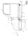
- both the driver's cab 1 and the bonnet 2 are carried on the frame 3 of the vehicle.
- the principle components of the frame consist of two longitudinally extending frame members 4, 5 positioned at a distance from each other.
- the vehicle frame 3 is resiliently supported with respect to the two front wheels 6, which in turn are in contact with a surface 7 such as a road way.
- the driver's cab 1 is resiliently supported on the vehicle frame.
- the driver's cab is pivotally supported to the vehicle frame at the front edge of the vehicle cab by means of a pivot support 8 which consists of two pivot hinges, by means of which the vehicle cab is supported on a substantially U-shaped framework 9.
- the resilient support is achieved in the shown example primarily by means of the driver's cab, via its frame work 9, being resiliently supported at its rear edge by a spring arrangement 10.
- This arrangement is similarly arranged on the vehicle frame 3, for example by means of two spring members between the frame work and respective frame members 4, 5.
- a certain elasticity in the support can also be achieved at the front edge by providing the pivot supports with resilient bushes.
- the commercial vehicle in the shown example is arranged with the motor in front of the driver's cab 1.
- the motor is accordingly covered by the bonnet 2 which surrounds the motor forwardly and on both sides and connects with the cowl region 11 of the driver's cab.
- the bonnet is pivotally supported to the vehicle frame by means of a pivot link 12, whereby the bonnet can be moved between a closed position, which is shown by solid lines in Fig. 1, to a open position indicated by dotted lines.
- the bonnet 2 is fastened to the vehicle frame 3 by means of securing arrangements 13 arranged on either side of the vehicle, which shall be described in greater detail below.
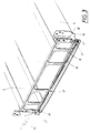
- Fig. 3 shows in greater detail an example of the pivot support 12 for the bonnet, where the pivot hinge is in the form of two crossed torsion bars 14, 15 which are pre-tensioned such that they apply a torque to the bonnet which counteracts the bonnet's own weight and thereby assists in the opening and closing of the bonnet.
- the torsion bars 14 and 15 are, in a known manner, fixedly secured at one end to a pivotable bracket 16 for each bar, and to which brackets the not shown bonnet is fixedly secured.
- the same end of each bar is resiliently supported for rotation within a fixed bearing housing 17 which is attached to a fixed bracket 18 which extends between, and is attached to, the two frame members 4, 5.
- each torsion bar is fixedly secured to the other bearing housing at an eccentrically located point, i.e. outside of the pivot axis.
- the open position of the pivotable bracket 16 is shown on the one side by dotted lines.
- the resilient support is achieved in the shown example by means of each bearing housing 17 being provided with a rubber bushing between the housing and the bar 14, 15 passing therethrough.
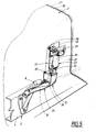
- Fig. 4 there is shown the connection of the bonnet 2 to the driver's cab, more exactly to the cowl region 11, i.e. the bulkhead between the driver's cab and the engine compartment.
- Essential for the present invention is that the bonnet 2 is not rigidly secured to the driver's cab, but rests thereagainst so that the driver's cab is allowed to move relative to the bonnet.
- the connection between the cab and the bonnet is so arranged, however, that rain water and the like cannot run into the engine compartment.
- the connection is achieved with the aid of a box girder 20 arranged at a distance from the rear edge 21 of the bonnet which overlappingly projects above the cowl region 11.
- a sealing strip 22 on one wall region 23 of the box girder 20.
- the strip 22 is very flexible whilst still providing sealing qualities so that the movement of the driver's cab is not transmitted to the bonnet.
- the bonnet is so arranged that, in principle it does not need to have any direct contact with the driver's cab or cowling other than via the sealing strip 22.
- the rear edge 21 and associated region of the bonnet presents a gap between the upwardly facing region 24 of the cowl 11 so that unnecessary abrasion, with resulting paint damage, is avoided.
- damping bodies 25 of elastic material In the corners of the cowl region 11 there are arranged damping bodies 25 of elastic material so that, in the bonnets' closed position, they have a stabilizing effect thereupon, particularly in a transverse direction, in order to avoid for example large oscillating amplitude with the risk of self oscillation.
- securing of the bonnet 2 is effected by securing the bonnet in the region of its rear edge to the vehicle chassis and not by means of any attachment to the driver's cab.
- the securing arrangement 13 is advantageously so designed that a relatively solid attachment to the vehicle frame 3 is attained, suitably so that the securing arrangement applies a pretensioned force which acts so as to pull the bonnet downwardly in a direction towards the vehicle frame.
- two securing arrangements are arranged, one on either side of the bonnet.
- the bonnet presents not only a front region 29 and an upper region 30 but also two side regions 31, whereby the upper region 30 and the two side regions 31 are rearwardly delimited by the rear edge 21 of the bonnet.
- each of the securing arrangements 13 presents a frame part 26 with a bracket 32 which is affixed to one member 4 of the vehicle frame and presents an upwardly facing support surface 33 and a ring 34 connected to the support surface and fixed to the bracket 32.
- a bonnet portion 27 of the securing arrangement similarly presents a bracket 35 on the bonnet, preferably attached to the reinforcement girder 20, which presents a downwardly directed support surface 36 which is intended to abut the upwardly facing support surface 33 of the frame bracket 32 in the closed position for the bonnet, as shown in Fig. 5.
- a hook element 37 is arranged on the bonnet bracket 35 and is adapted to engage the ring 34 and, via an eccentric arrangement, is pivotally carried on an axle rod 38. Rotation is achieved by means of an operating lever 39 which is accessible from the outer side of the bonnet within a recessed opening in the bonnet, whilst remaining parts of the securing arrangement 13 are hidden and protected underneath the bonnet.
- the operating handle 39 is also rotatable about its attachment 40 to the axle rod for displacement to an outwardly folded operational position and an inwardly folded storage position which is shown in dotted lines. From the shown operational position, a released position is reached by turning the operating lever in a clockwise direction, whereby the hook element 37 is downwardly displaced with respect to the shown engaged position and moved to the side of the ring 34 at the same time that the hooked end 41 maintains a greater distance from the rotational axis of the axle rod 38.
- Displacement to the secured position occurs by rotating the operating lever 39 anticlockwise, whereby the hook element 37 is brought to rotate anticlockwise and the hooked end 41 is inserted into the ring 34, whereafter, because of the eccentricity, the hook element 37, during continued rotation of the operating lever 9 to an end position, is lifted to thereby apply a pre-tensioning force so that the support surfaces 33, 36 on the two brackets 32, 35 are pressed together to thereby impart a stable and playless securement.
- the contact surfaces are not flat, but instead are formed so that a shaped engagement is achieved which provides additional transverse stability to the attachment.
- the driver's cabs' suspension can be designed for optimal driver comfort without regard to influences from the bonnet.
- the bonnet is securely attached to the frame, whereby the bonnet can be constructed so as to fulfil its primary functions.
- the securing arrangements 13 can be formed in a different manner than that shown in the chosen embodiment.
- a so-called tensioning clamp of the type which is used for fastening drop-sides on load platforms can be selected.
Landscapes
- Engineering & Computer Science (AREA)
- Chemical & Material Sciences (AREA)
- Combustion & Propulsion (AREA)
- Transportation (AREA)
- Mechanical Engineering (AREA)
- Superstructure Of Vehicle (AREA)
- Outer Garments And Coats (AREA)
Claims (3)
- Motorhaubenanordnung (2) für Nutzfahrzeuge mit einem Führerhaus (1), welches entfernbar auf einem Fahrzeugrahmen (3) des Fahrzeugs derart getragen ist, daß das Führerhaus (1) in der Lage ist, gedämpfte Federbewegungen relativ zu dem Fahrzeugrahmen durchzuführen, wobei die Motorhaube in ihrem Vorderbereich eine Schwenklagerung (12) für das kippbare Anbringen der Motorhaube (2) an den Fahrzeugrahmen (3) aufweist, wobei die Motorhaube (2) und das Führerhaus (1) unabhängig von einander von dem Fahrzeugrahmen (3) getragen werden und an diesen angebracht sind, indem die Motorhaube lösbar an den Fahrzeugrahmen über eine Festhalteeinrichtung (13) befestigt ist, die beabstandet von der Schwenklagerung (12) an jeder Seite der Motorhaube (2) im Bereich des hinteren Randes (21) der Motorhaube angebracht ist,
dadurch gekennzeichnet,
daß das Führerhaus zur Durchführung von Federbewegungen relativ zu dem Fahrzeugrahmen fähig ist, daß die Motorhaube (2) mit einem Abstand zwischen dem hinteren Rand (21) der Motorhaube und dem Führerhaus angeordnet ist, und daß der Abstand mittels eines abdichtenden flexiblen Streifens (22), welcher Abdichteigenschaften aufweist, abgedichtet wird, wobei das Führerhaus in der Lage ist, die Federbewegung relativ zu dem Fahrzeugrahmen, ohne daß Bewegungen des Führerhauses auf die Motorhaube übertragen werden, durchzuführen. - Anordnung nach Anspruch 1,
dadurch gekennzeichnet,
daß jede der Festhaltevorrichtungen (13) aus einem Rahmenteil (26), das an den Fahrzeugrahmen (3) angebracht ist, und aus einem Motorhaubenteil, das an die Motorhaube (2) angebracht ist, wobei beide Teile ineinandergreifende, aneinander stoßende Flächen (33, 34) aufweisen und aus einer Vorspannungsanordnung (34, 37, 38, 39) besteht, die zur Vorspannung des Motorhaubenteils gegen das Rahmenteil in der geschlossenen Stellung der Motorhaube ausgelegt ist. - Anordnung nach Anspruch 1,
dadurch gekennzeichnet,
daß die Vorspannungsanordnung (34, 37, 38, 39) einerseits als ein hakenförmiges Bauelement ausgebildet ist, das an dem Motorhaubenteil (35) angeordnet ist und über einen Bedienhebel (39) zwischen einer Vorspannungsposition und einer gelösten Position verstellbar ist, und andererseits als ein an dem Rahmenteil (26) ausgebildeter Ring (34) ausgebildet ist, in welchen das hakenförmige Bauelement in Eingriff bringbar ist.
Applications Claiming Priority (3)
| Application Number | Priority Date | Filing Date | Title |
|---|---|---|---|
| SE9102443 | 1991-08-26 | ||
| SE9102443A SE470352B (sv) | 1991-08-26 | 1991-08-26 | Anordning vid motorhuvar för lastfordon |
| PCT/SE1992/000594 WO1993003948A1 (en) | 1991-08-26 | 1992-08-26 | Bonnet arrangement for commercial vehicle |
Publications (2)
| Publication Number | Publication Date |
|---|---|
| EP0599997A1 EP0599997A1 (de) | 1994-06-08 |
| EP0599997B1 true EP0599997B1 (de) | 1998-11-18 |
Family
ID=20383543
Family Applications (1)
| Application Number | Title | Priority Date | Filing Date |
|---|---|---|---|
| EP92918579A Expired - Lifetime EP0599997B1 (de) | 1991-08-26 | 1992-08-26 | Motorhaube für nutzfahrzeuge |
Country Status (7)
| Country | Link |
|---|---|
| EP (1) | EP0599997B1 (de) |
| AT (1) | ATE173440T1 (de) |
| AU (1) | AU658665B2 (de) |
| BR (1) | BR9206423A (de) |
| DE (1) | DE69227634T2 (de) |
| SE (1) | SE470352B (de) |
| WO (1) | WO1993003948A1 (de) |
Families Citing this family (1)
| Publication number | Priority date | Publication date | Assignee | Title |
|---|---|---|---|---|
| US5992550A (en) * | 1996-06-07 | 1999-11-30 | Scania Cv Ab | Device and method for suspending a tiltable engine bonnet with respect to a vehicle frame |
Family Cites Families (6)
| Publication number | Priority date | Publication date | Assignee | Title |
|---|---|---|---|---|
| FR1302645A (fr) * | 1961-07-21 | 1962-08-31 | Berliet Automobiles | Véhicule à ensemble capot-ailes-calandre |
| US3419099A (en) * | 1966-11-07 | 1968-12-31 | Pacific Car & Foundry Co | Truck hood |
| SE406304B (sv) * | 1977-09-19 | 1979-02-05 | Saab Scania Ab | Lasmekanism for luckor och huvar pa fordon |
| DD154260A3 (de) * | 1980-06-13 | 1982-03-10 | Norbert Linkelmann | Anordnung von drehstaeben an kippbaren fahrerhaeusern von kraftfahrzeugen |
| AU553221B2 (en) * | 1980-10-09 | 1986-07-10 | Paccar Australia Pty. Ltd. | Vehicle cab suspension |
| US4676083A (en) * | 1986-03-07 | 1987-06-30 | Sedley Bruce S | Locking mechanism with actuator |
-
1991
- 1991-08-26 SE SE9102443A patent/SE470352B/sv unknown
-
1992
- 1992-08-26 AT AT92918579T patent/ATE173440T1/de not_active IP Right Cessation
- 1992-08-26 AU AU24967/92A patent/AU658665B2/en not_active Ceased
- 1992-08-26 BR BR9206423A patent/BR9206423A/pt not_active IP Right Cessation
- 1992-08-26 EP EP92918579A patent/EP0599997B1/de not_active Expired - Lifetime
- 1992-08-26 DE DE69227634T patent/DE69227634T2/de not_active Expired - Fee Related
- 1992-08-26 WO PCT/SE1992/000594 patent/WO1993003948A1/en not_active Ceased
Also Published As
| Publication number | Publication date |
|---|---|
| EP0599997A1 (de) | 1994-06-08 |
| DE69227634D1 (de) | 1998-12-24 |
| DE69227634T2 (de) | 1999-04-15 |
| WO1993003948A1 (en) | 1993-03-04 |
| SE9102443D0 (sv) | 1991-08-26 |
| AU2496792A (en) | 1993-03-16 |
| SE9102443L (sv) | 1993-02-27 |
| AU658665B2 (en) | 1995-04-27 |
| SE470352B (sv) | 1994-01-31 |
| ATE173440T1 (de) | 1998-12-15 |
| BR9206423A (pt) | 1995-11-14 |
Similar Documents
| Publication | Publication Date | Title |
|---|---|---|
| US4372569A (en) | Single wheel trailer support | |
| JPH09286354A (ja) | 小型車両の車体フレーム装置 | |
| US6315374B1 (en) | Track tensioning device for tracked automotive vehicles | |
| US4235470A (en) | Utility vehicle with a self-contained driver compartment | |
| US9216778B1 (en) | Cab suspension | |
| US4638878A (en) | Device for the cushioned mounting of a tractor cab | |
| US4465300A (en) | Vehicle suspension for rough terrain | |
| GB2166094A (en) | Road vehicle | |
| EP0599997B1 (de) | Motorhaube für nutzfahrzeuge | |
| JP3957767B2 (ja) | 操舵組立体 | |
| JP4038093B2 (ja) | トラクタの振動低減装置 | |
| WO2010005346A1 (en) | Vehicle cab arrangement | |
| JP2604056Y2 (ja) | キャブチルト装置 | |
| JP2543580Y2 (ja) | ウイングドアの開閉構造 | |
| RU2306238C1 (ru) | Подвеска кабины грузового автомобиля | |
| KR200153472Y1 (ko) | 자동차의 스테이빌라이저 바와 쇽 어브소버 장착구조 | |
| KR100488598B1 (ko) | 텐션로드를 구비한 차량의 서스펜션 | |
| JPH042862Y2 (de) | ||
| JP3376589B2 (ja) | 移動車両のハンドル支持装置 | |
| JP2564239Y2 (ja) | キャブチルト装置 | |
| JPH0356465Y2 (de) | ||
| JP2625104B2 (ja) | 小型車両の車輪懸架装置 | |
| JP2589754Y2 (ja) | キャブのチルトヒンジ機構 | |
| US4609063A (en) | Vehicle hood mounting | |
| JPS6036526Y2 (ja) | テイルトキヤブのフロントマウント装置 |
Legal Events
| Date | Code | Title | Description |
|---|---|---|---|
| PUAI | Public reference made under article 153(3) epc to a published international application that has entered the european phase |
Free format text: ORIGINAL CODE: 0009012 |
|
| 17P | Request for examination filed |
Effective date: 19940225 |
|
| AK | Designated contracting states |
Kind code of ref document: A1 Designated state(s): AT BE DE ES FR GB IT NL SE |
|
| 17Q | First examination report despatched |
Effective date: 19950828 |
|
| GRAG | Despatch of communication of intention to grant |
Free format text: ORIGINAL CODE: EPIDOS AGRA |
|
| GRAG | Despatch of communication of intention to grant |
Free format text: ORIGINAL CODE: EPIDOS AGRA |
|
| GRAH | Despatch of communication of intention to grant a patent |
Free format text: ORIGINAL CODE: EPIDOS IGRA |
|
| GRAH | Despatch of communication of intention to grant a patent |
Free format text: ORIGINAL CODE: EPIDOS IGRA |
|
| GRAA | (expected) grant |
Free format text: ORIGINAL CODE: 0009210 |
|
| AK | Designated contracting states |
Kind code of ref document: B1 Designated state(s): AT BE DE ES FR GB IT NL SE |
|
| PG25 | Lapsed in a contracting state [announced via postgrant information from national office to epo] |
Ref country code: ES Free format text: THE PATENT HAS BEEN ANNULLED BY A DECISION OF A NATIONAL AUTHORITY Effective date: 19981118 Ref country code: BE Free format text: LAPSE BECAUSE OF FAILURE TO SUBMIT A TRANSLATION OF THE DESCRIPTION OR TO PAY THE FEE WITHIN THE PRESCRIBED TIME-LIMIT Effective date: 19981118 Ref country code: AT Free format text: LAPSE BECAUSE OF FAILURE TO SUBMIT A TRANSLATION OF THE DESCRIPTION OR TO PAY THE FEE WITHIN THE PRESCRIBED TIME-LIMIT Effective date: 19981118 |
|
| REF | Corresponds to: |
Ref document number: 173440 Country of ref document: AT Date of ref document: 19981215 Kind code of ref document: T |
|
| REF | Corresponds to: |
Ref document number: 69227634 Country of ref document: DE Date of ref document: 19981224 |
|
| ITF | It: translation for a ep patent filed | ||
| ET | Fr: translation filed | ||
| PLBE | No opposition filed within time limit |
Free format text: ORIGINAL CODE: 0009261 |
|
| 26N | No opposition filed | ||
| REG | Reference to a national code |
Ref country code: GB Ref legal event code: IF02 |
|
| PGFP | Annual fee paid to national office [announced via postgrant information from national office to epo] |
Ref country code: NL Payment date: 20080803 Year of fee payment: 17 Ref country code: DE Payment date: 20080912 Year of fee payment: 17 |
|
| PGFP | Annual fee paid to national office [announced via postgrant information from national office to epo] |
Ref country code: IT Payment date: 20080827 Year of fee payment: 17 Ref country code: FR Payment date: 20080818 Year of fee payment: 17 |
|
| PGFP | Annual fee paid to national office [announced via postgrant information from national office to epo] |
Ref country code: GB Payment date: 20080903 Year of fee payment: 17 |
|
| PGFP | Annual fee paid to national office [announced via postgrant information from national office to epo] |
Ref country code: SE Payment date: 20080807 Year of fee payment: 17 |
|
| REG | Reference to a national code |
Ref country code: NL Ref legal event code: V1 Effective date: 20100301 |
|
| GBPC | Gb: european patent ceased through non-payment of renewal fee |
Effective date: 20090826 |
|
| REG | Reference to a national code |
Ref country code: FR Ref legal event code: ST Effective date: 20100430 |
|
| PG25 | Lapsed in a contracting state [announced via postgrant information from national office to epo] |
Ref country code: NL Free format text: LAPSE BECAUSE OF NON-PAYMENT OF DUE FEES Effective date: 20100301 Ref country code: FR Free format text: LAPSE BECAUSE OF NON-PAYMENT OF DUE FEES Effective date: 20090831 Ref country code: DE Free format text: LAPSE BECAUSE OF NON-PAYMENT OF DUE FEES Effective date: 20100302 |
|
| PG25 | Lapsed in a contracting state [announced via postgrant information from national office to epo] |
Ref country code: GB Free format text: LAPSE BECAUSE OF NON-PAYMENT OF DUE FEES Effective date: 20090826 |
|
| PG25 | Lapsed in a contracting state [announced via postgrant information from national office to epo] |
Ref country code: IT Free format text: LAPSE BECAUSE OF NON-PAYMENT OF DUE FEES Effective date: 20090826 |
|
| PG25 | Lapsed in a contracting state [announced via postgrant information from national office to epo] |
Ref country code: SE Free format text: LAPSE BECAUSE OF NON-PAYMENT OF DUE FEES Effective date: 20090827 |