EP0599123A2 - Transfer device for bath or shower, especially for physically handicapped persons - Google Patents
Transfer device for bath or shower, especially for physically handicapped persons Download PDFInfo
- Publication number
- EP0599123A2 EP0599123A2 EP93118105A EP93118105A EP0599123A2 EP 0599123 A2 EP0599123 A2 EP 0599123A2 EP 93118105 A EP93118105 A EP 93118105A EP 93118105 A EP93118105 A EP 93118105A EP 0599123 A2 EP0599123 A2 EP 0599123A2
- Authority
- EP
- European Patent Office
- Prior art keywords
- blades
- row
- transfer system
- holding device
- bed
- Prior art date
- Legal status (The legal status is an assumption and is not a legal conclusion. Google has not performed a legal analysis and makes no representation as to the accuracy of the status listed.)
- Granted
Links
Images
Classifications
-
- A—HUMAN NECESSITIES
- A61—MEDICAL OR VETERINARY SCIENCE; HYGIENE
- A61G—TRANSPORT, PERSONAL CONVEYANCES, OR ACCOMMODATION SPECIALLY ADAPTED FOR PATIENTS OR DISABLED PERSONS; OPERATING TABLES OR CHAIRS; CHAIRS FOR DENTISTRY; FUNERAL DEVICES
- A61G7/00—Beds specially adapted for nursing; Devices for lifting patients or disabled persons
- A61G7/10—Devices for lifting patients or disabled persons, e.g. special adaptations of hoists thereto
- A61G7/1001—Devices for lifting patients or disabled persons, e.g. special adaptations of hoists thereto specially adapted for specific applications
- A61G7/1003—Devices for lifting patients or disabled persons, e.g. special adaptations of hoists thereto specially adapted for specific applications mounted on or in combination with a bath-tub
-
- A—HUMAN NECESSITIES
- A61—MEDICAL OR VETERINARY SCIENCE; HYGIENE
- A61G—TRANSPORT, PERSONAL CONVEYANCES, OR ACCOMMODATION SPECIALLY ADAPTED FOR PATIENTS OR DISABLED PERSONS; OPERATING TABLES OR CHAIRS; CHAIRS FOR DENTISTRY; FUNERAL DEVICES
- A61G7/00—Beds specially adapted for nursing; Devices for lifting patients or disabled persons
- A61G7/10—Devices for lifting patients or disabled persons, e.g. special adaptations of hoists thereto
- A61G7/1013—Lifting of patients by
- A61G7/1019—Vertical extending columns or mechanisms
-
- A—HUMAN NECESSITIES
- A61—MEDICAL OR VETERINARY SCIENCE; HYGIENE
- A61G—TRANSPORT, PERSONAL CONVEYANCES, OR ACCOMMODATION SPECIALLY ADAPTED FOR PATIENTS OR DISABLED PERSONS; OPERATING TABLES OR CHAIRS; CHAIRS FOR DENTISTRY; FUNERAL DEVICES
- A61G7/00—Beds specially adapted for nursing; Devices for lifting patients or disabled persons
- A61G7/10—Devices for lifting patients or disabled persons, e.g. special adaptations of hoists thereto
- A61G7/1049—Attachment, suspending or supporting means for patients
- A61G7/1055—Suspended platforms, frames or sheets for patient in lying position
-
- A—HUMAN NECESSITIES
- A61—MEDICAL OR VETERINARY SCIENCE; HYGIENE
- A61G—TRANSPORT, PERSONAL CONVEYANCES, OR ACCOMMODATION SPECIALLY ADAPTED FOR PATIENTS OR DISABLED PERSONS; OPERATING TABLES OR CHAIRS; CHAIRS FOR DENTISTRY; FUNERAL DEVICES
- A61G2200/00—Information related to the kind of patient or his position
- A61G2200/30—Specific positions of the patient
- A61G2200/32—Specific positions of the patient lying
-
- A—HUMAN NECESSITIES
- A61—MEDICAL OR VETERINARY SCIENCE; HYGIENE
- A61G—TRANSPORT, PERSONAL CONVEYANCES, OR ACCOMMODATION SPECIALLY ADAPTED FOR PATIENTS OR DISABLED PERSONS; OPERATING TABLES OR CHAIRS; CHAIRS FOR DENTISTRY; FUNERAL DEVICES
- A61G7/00—Beds specially adapted for nursing; Devices for lifting patients or disabled persons
- A61G7/10—Devices for lifting patients or disabled persons, e.g. special adaptations of hoists thereto
- A61G7/1073—Parts, details or accessories
- A61G7/1076—Means for rotating around a vertical axis
Definitions
- the present invention relates to a transfer system for bathing and showering, in particular in the case of physically handicapped persons, in order to ensure the safe and convenient transport from bed to bath tub and vice versa in their hygienic and therapeutic care, consisting of a horizontal support arm which at one end in a lifting and the rotating device is mounted and on the other hand has a connecting element to which at least two vertical support rails for receiving support means for the physically handicapped, such as seated or lying shells, are fastened.
- Such transfer devices are commonly used in facilities to facilitate nursing where they serve the transportation and storage of the physically disabled. In bathing facilities, they enable the safe and comfortable transfer of patients into and out of bathtubs that cannot be used by the physically handicapped without outside help.
- the boom is connected to the piston rod of a hydraulic lifting mechanism via a further compression fitting and can thus be raised and lowered and rotated about the cylinder axis. Due to its detachable and adjustable construction concept, this bracket can be dimensionally adjusted during assembly, so that previous measurements are not necessary. It can also turn on easily during operation apparatus and structural changes, changed treatment methods and changing ergonomic requirements can be adapted.
- Such brackets mounted on bathing devices form with their support devices stationary transfer devices that are limited to the area of a bathroom. The transport between patient room and bathroom must be ensured by a separate transport device.
- the aforementioned seating and lying shells can be part of the transport device and can only be connected to the support rails of the transfer device in the bathroom.
- a first disadvantage arises from the fact that the body surface of a patient in the aforementioned seat or lying shell is not accessible from all sides , and it is therefore difficult to dry it so completely after bathing that it can be lowered directly onto the bed or transported over long distances without the risk of a cold. To do this, it would be necessary to relocate the mostly bedridden patients to the seat or bed on which they are currently sitting, or to transfer them to another bed. Both would be possible - if at all - only with great effort and skill on the part of the nursing staff and would mean an increased risk.
- the invention seeks to remedy this.
- the invention as characterized in the claims, solves the problem of creating a transfer system which, with maximum relief for the nursing staff, ensures safe and comfortable patient transfer from bed to bath tub and vice versa and also takes on functions of hygienic and therapeutic care .
- washing and massaging in the bath tub and drying after removal from the bath water should be carried out gently and automatically by the transfer system.
- this object is achieved by the means as characterized in the version of the independent claim.
- Advantageous further developments are specified in the dependent claims.
- the advantages achieved with the invention are the relief of the nursing staff and the possibilities for better patient care. Since the patient transfer and washing, Cash and drying of the applicant according to the transfer device are performed largely automatically, the nursing Persona l of very strenuous, laborious and often risky actions is relieved, and affect this without compromising the quality of patient care.
- the activities of the nursing staff are limited to the coordination, monitoring and monitoring of the automated processes, for which a single nursing person is completely sufficient.
- the drying cycle approximately 5 minutes
- the patient can re-cover the bed and at the same time monitor the patient.
- the shovel bed which is largely made of plastic, is easy to clean and can be disinfected properly in a conventional manner.
- the transfer device according to the application not only facilitates the hygienic but also the therapeutic patient care and that the corresponding measures are carried out particularly gently will. This results in new and better opportunities for patient care. For example, this gentle treatment has made it possible to provide a perfect supply of burns. Medications can also be added to the warm air or whirl water to enable or enhance a therapeutic effect. Another advantage is that the advances made and improvements made in the development and implementation of care measures with the application-based transfer facility lead to their increased use and thus improve the quality and quantity of hygienic and therapeutic patient care.
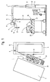
- Fig. 1, 1 denotes the transfer system according to the application, as is used in a station bath for transferring a physically handicapped person 2 between bed 3 and bath tub 4.
- the support arm 5, which is designed as a closed hollow profile with a rectangular cross section, is at one end in the Lifting and rotating device 6 can be raised and lowered and rotatably mounted about the vertical axis 7 and has at its other end a connecting element 9 rotatable about the vertical axis 8.
- the lifting and rotating device 6 is installed in a stationary manner on the foot side 10 of the bathtub 4 and designed as a hydraulic piston / cylinder unit with piston 11 and cylinder 12.
- the bathtub 4 has thermostatically controlled water filling and is set up in a frame made of stainless steel, so that it can be driven under and can be raised to an ergonomically favorable working height (approx. 100 cm).
- the connecting element 9 contains an upper holding device 13 with a schematically indicated warm air supply 14 and a lower holding device 16 which is height-adjustable relative to and relative to the support arm 5 by means of the lifting mechanism 15.
- the vertical support frame 17 carries at its lower end one of support blades 18 and a head part 19 with a joint 20 formed first blade row 21, which is required for all movements of the transfer system 1.
- the support frame 17 is therefore permanently attached to the upper holding device 13.
- the other vertical support frame 23 carries at its lower end in an analogous manner a second row of blades 24 formed from the same support blades 18, which is required for certain functions of the transfer system 1, but must be removed for others. Support frame 23 and row of blades 24 cannot be mounted, for example, in the patient position shown in FIG. 1, which is why they are only indicated in a hint.
- the vertical support frame 23 is therefore easily removable on the lower holding device 16, but still rigid.
- the first row of blades 21 and the second row of blades 24 together form the two-part blade bed 25.
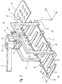
- FIG. 2 shows the connecting element 28 in a more detailed representation, as well as that of the two Support frame 17 and 23 suspended from the support arm 5, formed from the two rows of blades 21 and 24, two-part blade bed 25.
- the connecting element 28 has an outer central vertical axis 29 and can be deflected about the same by a restricted deflection angle ⁇ 360 °. Furthermore, the structure of the connecting element 28 coincides with that of the connecting element 9 in FIG. 1; it again has an upper holding device 13 and a lower holding device 16, to which the first row of blades 21 are fastened via the supporting frame 17 and the second row of blades 24 via the supporting frame 23.
- the lower holding device 16 is equipped with a lifting mechanism 15, so that it can be adjusted in height relative to the support arm 5 and thus also relative to the upper holding device 13.
- the connecting element 28 contains a warm air generator 30 for feeding the air outlet openings 31 in the support blades 18 of the row of blades 21.
- the two-part blade bed 25 is composed of a first row of blades 21 and a second row of blades 24, both of which are mutually height-adjustable, interlock with one another and over which Support frame 17 and 23 are attached to the connecting element 28.
- the first row of blades 21 consists of a holding tube 32 and a warm air tube 33, both of which are held in the connection points 34, 35 on the support frame 17 and on which, for example, 6 support blades 18 are arranged at right angles and parallel to one another.
- the warm air pipe 33 enables warm air to be fed into the carrier blades 18 and, together with the holding tube 32, ensures a solid and sufficiently rigid connection between the carrier blades 18 and the carrier frame 17.
- the carrier blades 18 consist of easily disinfectable plastic. Their mutual distances d and the shape of their upper boundary surfaces 37 are selected so that they form a flat, horizontal lying surface 36 which is also comfortable for the physically handicapped 2.
- the carrying blades 18 are provided with air outlet openings 31, through which warm air is pressed outwards from the inside of the carrying blades 18 can.
- the row of blades 21 has a head part 19, which is connected via a joint 20 to the holding tube 32 and to the warm air pipe 33 and automatically adjusts to the correct back slope when the two-part blade bed 25 is lowered into the bath tub 4. Because of its non-releasable suspension on the upper holding device 13, the first row of blades 21 can be rotated about the vertical axis 29, but is otherwise rigidly connected to the support arm 5 and can only be displaced translationally about this in space.
- the second row of blades 24 is basically constructed in the same way as the first row of blades 21.
- support blades 18 and the associated vertical support frame 23 are connected via a holding tube 40 and a warm air tube 41 to form a torsionally rigid unit which, in contrast to the first row of blades 21, is easily detachable and height-adjustable is fastened to the connecting element 28.
- the lower holding device 16 is designed as an electrical or hydraulic lifting mechanism 15 and the vertical supporting frame 23 is fastened to it in a removable manner or pivoted away laterally or upwards.
- the second row of blades 24 can thus be adjusted in height relative to the first row of blades 21 (and thus also to the horizontal support arm 5).
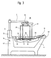
- FIG. 3 illustrates the interaction of transfer device 1 and bathtub 4 to form an integral bathing system for physically handicapped persons 2.
- 11 and 12 denote hydraulic pistons or cylinders, which form the lifting and rotating device 6, and both of which are located in the head-end desk 42 in this exemplary embodiment the bathtub 4 are installed stationary.
- the support arm 5 is pivoted in and lowered over the bathtub 4 in such a way that the two-part scoop bed 25 accommodating the physically disabled 2 is optimally placed in the bathtub 4 in terms of both care and ergonomics.
- the head part 19 is in contact with the tub edge 43 when the two-part bucket bed 25 is lowered, and as a result automatically sets itself into the correct back slope via the joint 20.
- the removable second row of blades 24 fastened to the support frame 23 height adjustable. In the exemplary embodiment shown, it is lowered relative to the first row of blades 21 fastened to the supporting frame 17, so that a physically handicapped person 2 in this case is only supported on the supporting blades 18 of the stationary row of blades 21.
- the height of the support arm 5 is adjusted by means of the lifting and rotating device 6, the vertical movement of the two rows of blades 21; 24 takes place synchronously, thereby lowering or raising the two-part blade bed 25 in the bathtub 4.
- the supporting blades 18 of the first, stationary row of blades 21 have lateral air outlet openings 31 on, can be blown by the warm air against the body of the disabled 2 and against the support blades 18 of the second row of blades 24.
- FIGS. 1, 2 and 3 Attention is drawn to FIGS. 1, 2 and 3, and the starting point is the sequence of movements which is typical for the bathing and showering operation of the physically handicapped. It is assumed that the bed 3 with the physically disabled 2 - for example in the ward bath - has come so close to the bath 4 that bed 3 and bath 4 are located in the area of the transfer system.
- the movement sequence is divided into three phases for better understanding:
- the first phase involves the rearrangement of the physically handicapped 2 from the bed 3 to the two-part shovel head 25 and vice versa:
- the physically handicapped person 2 is brought to the side on the mattress 22 and the first fixed shovel row 21 by actuating the lifting and rotating device 6 from behind brought his back up and lowered onto the mattress 22.
- the support blades 18 press the mattress 22 slightly downward in their areas, so that the physically disabled 2 can be rolled over onto the first row of blades 21 as if by themselves.
- the row of blades 21 is then raised by about 10 cm together with the physically handicapped person 2 supported on it.
- Both the lowering of the row of blades 21 onto the mattress 22 and the subsequent lifting by approximately 10 cm take place by actuating the lifting and rotating device 6.
- the second blade row 24 is brought up to his body from below and the corresponding holding frame 23 in the lower holding device 16 of the connecting element 9 or 28 latched.
- the second row of blades 24 is therefore only attached to the lower holding device 16 after the rearrangement of the physically handicapped 2 has been carried out, and, when the lifting mechanism 15 is lowered, is pivoted in under the first row of blades 21 which has been raised about 10 cm.
- the rearrangement in the opposite direction - ie from the two-part bucket bed 25 to the bed 3 - is carried out in an analogous manner, except that the individual steps are carried out in the reverse order.
- the rearrangement of the physically handicapped 2 is based on the interaction between the two-part bucket bed 25 and a soft base, as well as on the absolute and mutual height adjustment of the two rows of buckets 21 and 24. This rearrangement process is safe and does not require any significant effort on the part of the Nursing staff
- the second phase comprises the transfer of the physically handicapped 2 stored on the two-part scoop bed 25 into and out of the bath tub 4.
- the means of transfer are also means of hygienic and therapeutic care.
- the turbulence generated in the water by the outflowing warm air causes a washing and massage effect on the physically disabled 2.
- the second row of blades 24 is raised and lowered alternately with respect to the first row of blades 21, so that the physically handicapped 2 alternately rests exclusively on the higher row of blades 21 or 24 and his skin is released through the carrying blades 18 of the respectively lower row of blades 21 or 24. This ensures that the washing and massage effect extends over the entire body surface of the physically disabled.
- the warm air is of central importance for the automatic drying of the physically disabled 2 after removal from the bath water.
- the warm air emerging from the air outlet openings 31 flows around the naked patient, who is seated on the two-part scoop bed 25, and dries and warms him. Because of the use of warm air, this is done in a particularly gentle and pleasant way. This can be of great advantage in case of skin burns. Also during automatic drying, the removable, second row of blades 24 is alternately raised and lowered, so that the drying effect also extends essentially over the entire skin surface. Since the drying process, which takes approx. 5 minutes, runs automatically, the caregiver only needs to monitor the patient and can do another job during this time in the ward bath, for example, make a new bed.
- the invention need not be limited to the aforementioned exemplary embodiment.
- the pivoting in and out of the Support arms 5 for transferring patients into and out of the bathtub 4 take place fully automatically, as does switching on the warm air system or alternately raising and lowering the second, removable row of blades 24 when washing, drying or massaging.
- a ceiling-mounted running rail can be provided with a trolley designed as a lifting device, on which the connecting element 9 or 28 can be rotated about a vertical axis.
- the holding tube 32, the warm air tube 33, the support blades 18 and the support frames 17 and 23 can each form an integrating unit which is made of the same material, for example fiber-reinforced polystyrene.
Abstract
Description
Die vorliegende Erfindung betrifft ein Transfersystem für den Bade- und Duschbetrieb, insbesondere bei Körperbehinderten, um bei deren hygienischer und therapeutischer Versorgung den sicheren und bequemen Transport vom Bett in die Badewanne und umgekehrt zu gewährleisten, bestehend aus einem horizontalen Tragarm der einerends in einer Hebe- und Drehvorrichtung gelagert ist und anderends ein Verbindungselement aufweist, an dem mindestens zwei vertikale Tragschienen zur Aufnahme von Stützmitteln für Körperbehinderte, wie Sitz- oder Liegeschalen, befestigt sind.
Solche Transfereinrichtungen werden allgemein in Einrichtungen zur Erleichterung der Krankenpflege eingesetzt, wo sie dem Transport und der Lagerung von Körperbehinderten dienen. Bei Badeeinrichtungen ermöglichen sie das sichere und bequeme Überführen von Patienten in und aus Badewannen, welche von Körperbehinderten nicht ohne fremde Hilfe benützt werden können.The present invention relates to a transfer system for bathing and showering, in particular in the case of physically handicapped persons, in order to ensure the safe and convenient transport from bed to bath tub and vice versa in their hygienic and therapeutic care, consisting of a horizontal support arm which at one end in a lifting and the rotating device is mounted and on the other hand has a connecting element to which at least two vertical support rails for receiving support means for the physically handicapped, such as seated or lying shells, are fastened.
Such transfer devices are commonly used in facilities to facilitate nursing where they serve the transportation and storage of the physically disabled. In bathing facilities, they enable the safe and comfortable transfer of patients into and out of bathtubs that cannot be used by the physically handicapped without outside help.
Die Zahl der Schwerstpflegefälle in den Geriatrieabteilungen von Krankenhäusern und Pflegeheimen nimmt laufend zu. Diese Patienten sind bettlägrig und müssen im Bett gepflegt werden. Dabei ergeben sich Liegeschäden (Decubitis), was die Körperhygiene, der in der Regel inkontinenten Patienten enorm erschwert. Die Reinhaltung bzw. das Waschen und Baden dieser Patienten stellt gegenwärtig eines der grössten Probleme in der Krankenpflege dar.The number of extremely difficult care cases in the geriatric departments of hospitals and nursing homes is constantly increasing. These patients are bedridden and need to be cared for in bed. This results in lying damage (decubitis), which makes body hygiene, which is usually extremely difficult for incontinent patients, extremely difficult. Maintaining or washing and bathing these patients is currently one of the biggest problems in nursing.
Heute werden diese Patienten mit möglichst wenig Wasser im Bett gewaschen, oder z.B. mit einem Tuch-/Gurt-Patientenlifter im Patientenzimmer aus dem Bett übernommen, ins Badezimmer überführt und dort unter die Dusche oder in die Badewanne gebracht. Andererseits sind in neueren Spitälern und Heimen die Gänge und Türen oft bewusst auf eine grössere Breite ausgelegt, sodass mit dem Bett ins Badezimmer gefahren werden kann, wo der Patient direkt vom Bett unter die Dusche oder in die Badewanne transferiert wird.
Tuch-/Gurt-Patientenlifter haben den Nachteil, dass sie sich schlecht für den Krankentransport eignen. Überführungen mit in Gurten hängenden Patienten werden nur ungern durchgeführt - auch über kurze Strecken. Im weitern sind die Transportgurte und die Transporttücher nach dem Baden so nass, dass der Patient nicht sofort auf das Bett abgesenkt werden kann. Vielmehr müssen die Transfereinrichtungen nach dem Baden zuerst gereinigt und getrocknet werden, bevor zurück ins Bett transferiert werden kann, - beides Arbeitsvorgänge, die im Falle von Transportgurten und Transporttüchern viel Arbeit und Zeit erfordern.Today, these patients are washed in bed with as little water as possible, or, for example, taken out of bed with a cloth / belt patient hoist in the patient's room, transferred to the bathroom and there under the shower or bathtub brought. On the other hand, in newer hospitals and nursing homes, the corridors and doors are often deliberately designed to have a larger width so that the bed can be taken to the bathroom, where the patient is transferred directly from the bed to the shower or bathtub.
Cloth / belt patient hoists have the disadvantage that they are poorly suited for patient transportation. Transfers with patients hanging in belts are reluctant to carry out - even over short distances. Furthermore, the transport straps and the transport cloths are so wet after bathing that the patient cannot be lowered onto the bed immediately. Rather, the transfer devices have to be cleaned and dried after bathing before they can be transferred back to bed - both operations that require a lot of work and time in the case of transport belts and transport towels.
Es ist denn auch eine grosse Anzahl weiterer Vorrichtungen bekannt geworden, um Patienten und Behinderten den Weg vom Patientenbett in die Badewanne und zurück mit technischen Hilfsmitteln zu erleichtern oder überhaupt erst zu ermöglichen. So ist aus dem Europäischen Patent Nr.0 117 992 der Anmelderin ein Ausleger für heb- und drehbare Sitz- und Liegeanordnungen bekannt, mit dem Körperbehinderte in sitzender oder liegender Stellung ins Bad oder unter die Dusche transferiert werden können und umgekehrt. Bei diesem Ausleger sind Profilelemente durch Klemmverschraubungen zusammengehalten, sodass eine technische Einrichtung entsteht, die lösbar und einstellbar ist. Dabei sind vertikale Stützschienen, die eine Sitz- oder Liegeanordnung tragen, über quaderförmige Verbindungsblöcke an einem horizontalen Tragarm befestigt und relativ zu diesem einzeln einstellbar. Über eine weitere Klemmverschraubung ist der Ausleger mit der Kolbenstange eines hydraulischen Hubwerkes verbunden und dadurch heb- und senkbar, sowie um die Zylinderachse drehbar gelagert. Aufgrund seines lösbaren und einstellbaren Aufbaukonzeptes lässt sich dieser Ausleger bei der Montage dimensionsmässig einstellen, so dass vorgängige Massaufnehmen entfallen. Weiter kann er im Betrieb leicht an apparative und bauliche Umstellungen, geänderte Behandlungsmethoden sowie wechselnde ergonomische Anforderungen angepasst werden. Solche, an Badeeinrichtungen montierte Ausleger bilden mit ihren Stützeinrichtungen stationäre Transfereinrichtungen, die auf den Bereich eines Badezimmers beschränkte sind. Der Transport zwischen Patientenzimmer und Badezimmer muss durch eine separate Transporteinrichtung gewährleistet sein. Dabei können die vorgenannten Sitz- und Liegeschalen Teil der Transporteinrichtung sein und erst im Badezimmer mit den Stützschienen der Transfereinrichtung verbunden werden.
Obwohl der vorgenannte Ausleger den Transfer von Patienten in und aus Badewannen ganz wesentlich erleichtert, haften ihm doch gewisse Nachteile an: Ein erster Nachteil ergibt sich aus dem Umstande, dass die Körperoberfläche eines sich in der vorgenannten Sitz- oder Liegeschale befindenden Patienten nicht allseits zugänglich ist, und es deshalb schwierig ist, ihn nach dem Bade so vollständig abzutrocknen, dass er direkt auf das Bett abgesenkt oder ohne Gefahr von Erkältung auch über grössere Strecken transportiert werden kann. Hierzu wäre es erforderlich, die meist bettlägrigen Patienten auf der Sitz - oder Liegeschale, auf der sie sich gerade befinden, umzulagern oder sie auf eine andere Liege zu transferieren. Beides wäre - wenn überhaupt - nur mit grossem Aufwand an Kraft und Geschicklichkeit seitens des Pflegepersonals möglich und würde ein erhöhtes Risiko bedeuten. Weiter hat sich als nachteilig erwiesen, dass der Ausleger gemäss EU-0 117 992 in seiner Funktion ausschliesslich auf den Patiententransfer beschränkt ist. Obwohl er die Versorgung von Körperbehinderten wesentlich erleichtert kann er selber weder für hygienische noch für therapeutische Funktionen eingesetzt werden. Zum automatischen Waschen und Massieren ist man deshalb auf stationäre, in der Badewanne fest installierte Whirl-Einrichtungen angewiesen. Diese sind therapeutisch zwar günstig, hygienisch stellen sie aber ein Problem dar. Ihre Desinfektion kann nämlich nur bedingt gewährleistet werden, so dass das Verschleppen von Keimen zwischen den einzelnen Bädern kaum zu vermeiden ist und sich daraus ein grosses Risiko für Kreuzinfektionen ergibt.A large number of other devices have also become known in order to make it easier for patients and the disabled to get from the patient bed into the bathtub and back with technical aids, or to enable them in the first place. For example, from the European Patent No. 0 117 992 of the applicant, an extension arm for lifting and rotating seating and lying arrangements is known, with which physically handicapped persons can be transferred to the bath or shower in the sitting or lying position and vice versa. In this boom, profile elements are held together by compression fittings, so that a technical device is created that is detachable and adjustable. Vertical support rails, which carry a seat or lying arrangement, are fastened to a horizontal support arm by means of cuboid connecting blocks and can be individually adjusted relative to this. The boom is connected to the piston rod of a hydraulic lifting mechanism via a further compression fitting and can thus be raised and lowered and rotated about the cylinder axis. Due to its detachable and adjustable construction concept, this bracket can be dimensionally adjusted during assembly, so that previous measurements are not necessary. It can also turn on easily during operation apparatus and structural changes, changed treatment methods and changing ergonomic requirements can be adapted. Such brackets mounted on bathing devices form with their support devices stationary transfer devices that are limited to the area of a bathroom. The transport between patient room and bathroom must be ensured by a separate transport device. The aforementioned seating and lying shells can be part of the transport device and can only be connected to the support rails of the transfer device in the bathroom.
Although the above-mentioned arm makes the transfer of patients in and out of bathtubs much easier, it has certain disadvantages: A first disadvantage arises from the fact that the body surface of a patient in the aforementioned seat or lying shell is not accessible from all sides , and it is therefore difficult to dry it so completely after bathing that it can be lowered directly onto the bed or transported over long distances without the risk of a cold. To do this, it would be necessary to relocate the mostly bedridden patients to the seat or bed on which they are currently sitting, or to transfer them to another bed. Both would be possible - if at all - only with great effort and skill on the part of the nursing staff and would mean an increased risk. It has also proven to be disadvantageous that the function of the boom according to EU-0 117 992 is restricted exclusively to patient transfer. Although it makes the care of the physically handicapped much easier, it cannot be used for hygienic or therapeutic functions. For automatic washing and massaging, one is therefore dependent on stationary whirl devices permanently installed in the bathtub. Although these are therapeutically inexpensive, hygienically they pose a problem. Their disinfection can only be guaranteed to a limited extent, so that the spread of germs between the individual baths can hardly be avoided and this results in a great risk of cross infections.
Hier will die Erfindung Abhilfe schaffen. Die Erfindung, wie sie in den Ansprüchen gekennzeichnet ist, löst die Aufgabe, ein Transfersystem zu schaffen, das bei maximaler Entlastung des Pflegepersonals, den sicheren und bequemen Patiententransfer vom Bett in die Badewanne und umgekehrt gewährleistet und zusätzlich auch Funktionen der hygienischen und therapeutischen Versorgung übernimmt. Insbesondere sollen das Waschen und Massieren in der Badewanne sowie das Trocknen nach dem Herausnehmen aus dem Badewasser vom Transfersystem schonend und automatisch ausgeführt werden.
Diese Aufgabe wird erfindungsgemäss mit den Mitteln gelöst, wie sie in der Fassung des unabhängigen Anspruches gekennzeichnet sind. Vorteilhafte Weiterbildungen sind in den abhängigen Ansprüchen angegeben.The invention seeks to remedy this. The invention, as characterized in the claims, solves the problem of creating a transfer system which, with maximum relief for the nursing staff, ensures safe and comfortable patient transfer from bed to bath tub and vice versa and also takes on functions of hygienic and therapeutic care . In particular, washing and massaging in the bath tub and drying after removal from the bath water should be carried out gently and automatically by the transfer system.
According to the invention, this object is achieved by the means as characterized in the version of the independent claim. Advantageous further developments are specified in the dependent claims.
Die mit der Erfindung erzielten Vorteile liegen in der Entlastung des Pflegepersonals und den Möglichkeiten zur besseren Patientenversorgung. Da der Patiententransfer sowie das Waschen, Kassieren und Trocknen von der antragsgemässen Transfereinrichtung weitgehend automatisch ausgeführt werden, wird das Pflegepersonal von sehr anstrengenden, umständlichen und oft auch risikoreichen Handlungen entlastet, und dies ohne die Qualität der Patientenversorgung zu beeinträchtigen. Die Tätigkeiten des Pflegepersonals beschränken sich auf die Koordination, Überwachung und Begleitung der ablaufenden Automatismen, wozu eine einzelne Pflegeperson völlig ausreichend ist. Diese kann, z.B. im Stationsbad, während der Dauer des Trocknungszyklus (ca. 5 Minuten) das Bett neu beziehen und dabei gleichzeitig den Patienten überwachen. Auch hat sich gezeigt, dass die weitgehend aus Kunststoff gefertigte Schaufelliege sich leicht reinigen lässt und auf herkömmliche Art einwandfrei desinfiziert werden kann. Als besonders vorteilhaft hat sich erwiesen, dass die antragsgemässe Transfereinrichtung nicht nur die hygienische sondern auch die therapeutische Patientenversorgung erleichtert und dass dabei die entsprechenden Massnahmen besonders schonend ausgeführt werden. Daraus ergeben sich neue und bessere Möglichkeiten der Patientenversorgung. So ist z.B. eine einwandfreie Versorgung von Verbrennungsfällen durch diese schonende Behandlung erst möglich geworden. Weiter können der Warmluft oder dem Whirl-Wasser Medikamente beigegeben werden, um so einen Therapieeffekt zu ermöglichen oder zu verstärken. Ein weiterer Vorteil besteht darin, dass die mit der antragsgemässen Transfereinrichtung erzielten Fortschritte und Erleichterungen bei der Entwicklung und Ausführung von Pflegemassnahmen zu deren vermehrten Anwendung führen und so die hygienische und therapeutische Patientenversorgung qualitativ und quantitativ verbessern.The advantages achieved with the invention are the relief of the nursing staff and the possibilities for better patient care. Since the patient transfer and washing, Cash and drying of the applicant according to the transfer device are performed largely automatically, the nursing Persona l of very strenuous, laborious and often risky actions is relieved, and affect this without compromising the quality of patient care. The activities of the nursing staff are limited to the coordination, monitoring and monitoring of the automated processes, for which a single nursing person is completely sufficient. During the drying cycle (approx. 5 minutes), for example in the ward bath, the patient can re-cover the bed and at the same time monitor the patient. It has also been shown that the shovel bed, which is largely made of plastic, is easy to clean and can be disinfected properly in a conventional manner. It has proven to be particularly advantageous that the transfer device according to the application not only facilitates the hygienic but also the therapeutic patient care and that the corresponding measures are carried out particularly gently will. This results in new and better opportunities for patient care. For example, this gentle treatment has made it possible to provide a perfect supply of burns. Medications can also be added to the warm air or whirl water to enable or enhance a therapeutic effect. Another advantage is that the advances made and improvements made in the development and implementation of care measures with the application-based transfer facility lead to their increased use and thus improve the quality and quantity of hygienic and therapeutic patient care.
Im folgenden wird die Erfindung anhand eines auf der Zeichnung dargestellten Ausführungsbeispieles näher erläutert. Es zeigen:
- Fig. 1
- schematisch, in Draufsicht und in Ansicht Disposition und prinzipieller Aufbau des erfindungsgemässen Transfersystems bei seiner Anwendung in einem Stationsbad zum Transfer eines Körperbehinderten vom Bett in die Badewanne und umgekehrt.
- Fig. 2
- schematisch, in perspektivischer Darstellung, Disposition und prinzipieller Aufbau der zweiteiligen Schaufelliege sowie deren Verbindung mit dem horizontalen Tragarm.
- Fig. 3
- schematisch, in Seitenansicht und teilweise im Vertikalschnitt, die Transfereinrichtung mit in die Badewanne abgesenkter zweiteiliger Schaufelliege.
- Fig. 1
- schematic, in top view and in view disposition and basic structure of the transfer system according to the invention when it is used in a station bath for transferring a physically disabled person from the bed into the bathtub and vice versa.
- Fig. 2
- schematic, in perspective, disposition and basic structure of the two-part bucket bed and its connection to the horizontal support arm.
- Fig. 3
- schematically, in side view and partly in vertical section, the transfer device with two-part scoop bed lowered into the bathtub.
In Fig. 1 ist mit 1 das antragsgemässe Transfersystem bezeichnet, wie es in einem Stationsbad zum Transfer eines Körperbehinderten 2 zwischen Bett 3 und Badewanne 4 eingesetzt ist. Der als geschlossenes Hohlprofil mit rechteckigem Querschnitt ausgebildete Tragarm 5, ist an einem Ende in der Hebe - und Drehvorrichtung 6 heb- und senkbar und um die Vertikalachse 7 drehbar gelagert und besitzt an seinem andern Ende ein um die Vertikalachse 8 drehbares Verbindungselement 9. Im vorliegenden Ausführungsbeispiel ist die Hebe- und Drehvorrichtung 6 an der Fusseite 10 der Badewanne 4 stationär eingebaut und als hydraulische Kolben-/Zylindereinheit mit Kolben 11 und Zylinder 12 ausgebildet. Die Badewanne 4 weist thermostatisch geregelte Wasserfüllung auf und ist in einem Rahmengestell aus Edelstahl aufgestellt, damit sie unterfahrbar ist und auf eine ergonomisch günstige Arbeitshöhe (ca. 100 cm) angehoben werden kann. Das Verbindungselement 9 enthält eine obere Haltevorrichtung 13 mit schematisch angedeuteter Warmluftzuführung 14 sowie eine mittels des Hubwerkes 15 relativ dazu und relativ zum Tragarm 5 höhenverstellbare untere Haltevorrichtung 16. Der vertikale Tragrahmen 17 trägt an seinem unteren Ende eine aus Tragschaufeln 18 und Kopfteil 19 mit Gelenk 20 gebildete erste Schaufelreihe 21, die für alle Bewegungsabläufe des Transfersystems 1 erforderlich ist. Der Tragrahmen 17 ist deshalb unlösbar an der oberen Haltevorrichtung 13 befestigt. In Fig.1 ist er durch Einstellen des Tragarmes 5 so positioniert, dass die Schaufelreihe 21, auf die Matratze 22 abgesenkt an den Rücken des Körperbehinderten 2 herangeführt ist und ihn so übernehmen kann.
Der andere vertikale Tragrahmen 23 trägt an seinem unteren Ende in analoger Weise eine aus gleichen Tragschaufeln 18 gebildete zweite Schaufelreihe 24, die für gewisse Funktionen des Transfersystems 1 erforderlich ist, für andere aber entfernt sein muss. Tragrahmen 23 und Schaufelreihe 24 können z.B. bei der in Fig.1 gezeigten Patientenlage nicht montiert sein, weshalb sie auch nur andeutungsweise wiedergegeben sind. Der vertikale Tragrahmen 23 ist deshalb an der unteren Haltevorrichtung 16 leicht wegnehmbar, aber doch verwindunssteif, befestigt. Die erste Schaufelreihe 21 und die zweite Schaufelreihe 24 bilden zusammen die zweiteilige Schaufelliege 25.In Fig. 1, 1 denotes the transfer system according to the application, as is used in a station bath for transferring a physically
The other
Fig. 2 zeigt in detaillierterer Darstellung das Verbindungselement 28 sowie die damit über die beiden Tragrahmen 17 bzw. 23 am Tragarm 5 aufgehängte, aus den beiden Schaufelreihen 21 und 24 gebildete, zweiteilige Schaufelliege 25. Das Verbindungselement 28 besitzt als Ausführungsvariante eine aussenmittige Vertikalachse 29 und ist um dieselbe um einen eingeschränkten Auslenkwinkel < 360° auslenkbar. Im weitern deckt sich aber der Aufbau des Verbindungselementes 28 mit demjenigen des Verbindunsgelementes 9 in Fig.1; weist es doch wieder eine obere Haltevorrichtung 13 und eine untere Haltevorrichtung 16 auf, an welchen die erste Schaufelreihe 21 über den Tragrahmen 17 bzw. die zweite Schaufelreihe 24 über den Tragrahmen 23 befestigt sind. Im Gegensatz zur oberen Haltevorrichtung 13 ist die untere Haltevorrichtung 16 mit einem Hubwerk 15 ausgerüstet, sodass sie relativ zum Tragarm 5 und damit auch relativ zur oberen Haltevorrichtung 13 höhenverstellbar ist. Zusätzlich enthält das Verbindungselement 28 einen Warmluftgenerator 30 zur Speisung der Luftaustrittsöffnungen 31 in den Tragschaufeln 18 der Schaufelreihe 21. Die zweiteilige Schaufelliege 25 setzt sich aus einer ersten Schaufelreihe 21 und einer zweiten Schaufelreihe 24 zusammen, die beide, gegenseitig höhenverstellbar, fingerförmig ineinandergreifen und über die Tragrahmen 17, bzw. 23 am Verbindungselement 28 befestigt sind. Die erste Schaufelreihe 21 besteht aus einem Halterohr 32 und einem Warmluftrohr 33, die beide in den Verbindungspunkten 34, 35 am Tragrahmen 17 gehalten sind und auf denen z.B. 6 Tragschaufeln 18, rechtwinklig und unter sich parallel verlaufend, angeordnet sind. Das Warmluftrohr 33 ermöglicht die Zuführung von Warmluft in die Tragschaufeln 18 und gewährleistet zusammen mit dem Halterohr 32 eine solide und ausreichend starre Verbindung zwischen den Tragschaufeln 18 und dem Tragrahmen 17. Die Tragschaufeln 18 bestehen aus leicht desinfizierbarem Kunststoff. Ihre gegenseitigen Abstände d sowie die Form ihrer oberen Begrenzungsflächen 37 sind so gewählt, dass sie eine ebene, horizontale, Liegefläche 36 bilden, die auch für Körperbehinderte 2 komfortabel ist. Entlang ihrer beiden Längsseiten 38,39 sind die Tragschaufeln 18 mit Luftaustrittsöffnungen 31 versehen, durch die warme Luft vom Innern der Tragschaufeln 18 nach aussen gepresst werden kann. Weiter besitzt die Schaufelreihe 21 ein Kopfteil 19, das über ein Gelenk 20 mit dem Halterohr 32 und mit dem Warmluftrohr 33 verbunden ist und sich beim Absenken der zweiteiligen Schaufelliege 25 in die Badewanne 4 automatisch in die richtige Rückenschräge einstellt. Die erste Schaufelreihe 21 ist aufgrund ihrer nicht-lösbaren Aufhängung an der oberen Haltevorrichtung 13 um die Vertikalachse 29 drehbar, sonst aber starr mit dem Tragarm 5 verbunden und nur über diesen im Raum translatorisch verschiebbar.
Die zweite Schaufelreihe 24 ist grundsätzlich gleich aufgebaut wie die erste Schaufelreihe 21. Wiederum sind Tragschaufeln 18 und der zugehörige vertikale Tragrahmen 23 über ein Halterohr 40 und ein Warmluftrohr 41 zu einer verwindungssteifen Einheit verbunden, die - im Gegensatz zur ersten Schaufelreihe 21 - leicht lösbar und höhenverstellbar am Verbindungselement 28 befestigt ist. Hierzu ist die untere Haltevorrichtung 16 als elektrisches oder hydraulisches Hubwerk 15 ausgebildet und daran der vertikale Tragrahmen 23 wegnehmbar oder seitlich bzw. nach oben wegschwenkbar befestigt. Die zweite Schaufelreihe 24 ist somit relativ zur ersten Schaufelreihe 21 (und damit auch zum horizontalen Tragarm 5) höhenverstellbar.FIG. 2 shows the connecting
The second row of
Die Fig. 3 illustriert das Zusammenwirken von Transfereinrichtung 1 und Badewanne 4 zu einem integralen Badesystem für Körperbehinderte 2. Wieder bezeichnen 11 und 12 hydraulische Kolben bzw. Zylinder, welche die Hebe- und Drehvorrichtung 6 bilden und welche beide in diesem Ausführungsbeispiel im kopfseitigen Pult 42 der Badewanne 4 stationär eingebaut sind. Der Tragarm 5 ist über der Badewanne 4 so eingeschwenkt und abgesenkt, dass die den Körperbehinderten 2 aufnehmende zweiteilige Schaufelliege 25 sowohl pflegerisch wie ergonomisch optimal in der Badewanne 4 plaziert ist. Das Kopfteil 19 steht beim Absenken der zweiteiligen Schaufelliege 25 an der Wannenkante 43 an, und stellt sich dadurch, über das Gelenk 20, automatisch in die richtige Rückenschräge. Über das elektrische oder hydraulische Hubwerk 15 im Verbindungselement 28 ist die am Tragrahmen 23 befestigte wegnehmbare zweite Schaufelreihe 24 höhenverstellbar. Im gezeigten Ausführungsbeispiel ist sie gegenüber der am Tragrahmen 17 befestigten ersten Schaufelreihe 21 abgesenkt, sodass ein Körperbehinderter 2 in diesem Falle, lediglich auf den Tragschaufeln 18 der stationären Schaufelreihe 21 gelagert ist. Bei Höhenverstellung des Tragarmes 5 mittels der Hebe- und Drehvorrichtung 6 erfolgt die Vertikalbewegung der beiden Schaufelreihen 21;24 synchron und dadurch ein Absenken oder Anheben der zweiteiligen Schaufelliege 25 in der Badewanne 4. Die Tragschaufeln 18 der ersten, stationären Schaufelreihe 21 weisen seitliche Luftaustrittsöffnungen 31 auf, durch die Warmluft gegen den Körper des Behinderten 2 und gegen die Tragschaufeln 18 der zweiten Schaufelreihe 24 geblasen werden kann.FIG. 3 illustrates the interaction of
Im Folgenden ist die Funktionsweise des antragsgemässen Transfersystems 1 näher erläutert. Dabei sei auf die Figuren 1,2 und 3 hingewiesen und vom Bewegungsablauf ausgegangen, wie er für den Bade- und Duschbetrieb von Körperbehinderten typisch ist. Es sei angenommen, dass das Bett 3 mit dem Körperbehinderten 2 - z.B. im Stationsbad - so nahe an die Badewanne 4 herangefahren sei, dass sich Bett 3 und Badewanne 4 im Bereiche des Transfersystems befinden. Zur besseren Verständlichkeit wird der Bewegungsablauf in drei Phasen aufgeteilt:
Die erste Phase beinhaltet die Umlagerung des Körperbehinderten 2 vom Bett 3 auf die zweiteilige Schaufellige 25 und umgekehrt: Hierzu wird der Körperbehinderte 2 auf der Matratze 22 in Seitenlage gebracht und die erste feststehende Schaufelreihe 21 durch Betätigen der Heb- und Drehvorrichtung 6, von hinten an seinen Rücken herangeführt und auf die Matratze 22 abgesenkt. Dabei pressen die Tragschaufeln 18 in ihrem Bereiche die Matratze 22 geringfügig nach unten, sodass der Körperbehinderte 2 - wie von alleine - auf die erste Schaufelreihe 21 überrollt werden kann. Anschliessend wird die Schaufelreihe 21 zusammen mit dem auf ihr gelagerten Körperbehinderten 2 um ca. 10 cm angehoben. Sowohl das Absenken der Schaufelreihe 21 auf die Matratze 22 wie das nachfolgende Anheben um ca. 10 cm erfolgen durch Betätigen der Hebe- und Drehvorrichtung 6. Nachdem der Körperbehinderte 2 auf der ca. 10 cm angehobenen Schaufelreihe 21 gelagert ist, wird die zweite Schaufelreihe 24 von unten an seinen Körper herangebracht und der entsprechende Halterahmen 23 in der unteren Haltevorrichtung 16 des Verbindungelementes 9 bzw. 28 eingeklinkt. Die zweite Schaufelreihe 24 wird also erst nach erfolgter Umlagerung des Körperbehinderten 2 an der unteren Haltevorrichtung 16 befestigt, und bei abgesenktem Hubwerk 15 unter die ca. 10 cm angehobene erste Schaufelreihe 21 eingeschwenkt. Durch leichtes Antippen des Hubwerkes 15 können die beiden Schaufelreihen 21 und 24 ausnivelliert werden, wodurch eine bequeme, gegen seitliches Herausfallen gesicherte Auflage entsteht. Die Umlagerung in Gegenrichtung - d.h. von der zweiteiligen Schaufelliege 25 auf das Bett 3 - erfolgt in analoger Weise, nur dass die einzelnen Schritte in umgekehrter Reihenfolge ausgeführt werden. Bei dem antragsgemässen Transfersystem beruht die Umlagerung von Körperbehinderten 2 auf der Wechselwirkung zwischen der zweiteiligen Schaufelliege 25 und einer weichen Unterlage sowie auf der absoluten und gegenseitigen Höhenverstellbarkeit der beiden Schaufelreihen 21 und 24. Dieses Umlagerungsverfahren ist sicher und erfordert in beiden Richtungen keinen wesentlichen Kraftaufwand seitens des Pflegepersonals Die zweite Phase umfasst die Überführung des auf der zweiteiligen Schaufelliege 25 gelagerten Körperbehinderten 2 in und aus der Badewanne 4. Diese Überführung erfolgt einfach und problemlos durch Einschwenken und Absenken der zweiteiligen Schaufelliege 25 mittels des in der Hebe- und Drehvorrichtung 6 gelagerten Tragarmes 5. Dabei ist es absolut erforderlich, dass der Warmluftgenerator 30 eingeschaltet ist, bevor die Schaufelliege 25 in das Badewasser eintaucht und auch eingeschaltet bleibt, solange die Schaufelliege 25 im Badewasser eingetaucht ist. Damit ist gewährleistet, dass bei eingetauchter Schaufelliege 25 dauernd Warmluft aus den Luftaustrittsöffnungen 31 geblasen wird. Dies, um das Eindringen von Badewasser und damit von Keimen in das Innere der Tragschaufeln 18 sowie der Warmluftzuleitungen zu verunmöglichen und dadurch das Risiko von Kreuzinfektionen zu reduzieren.
In der letzen, dritten Phase sind alle Massnahmen zusammengefasst, die der hygienischen und therapeutischen Versorgung des Körperbehinderten 2 dienen. Es ist nämlich ein wesentliches Merkmal des antragsgemässen Transfersystems, dass die Mittel zum Tansfer zugleich auch Mittel zur hygienischen und therapeutischen Versorgung sind. Die im Wasser durch die ausströmende Warmluft erzeugten Turbulenzen bewirken am Körperbehinderten 2 einen Wasch- und Massageeffekt. Gleichzeitig wird die zweite Schaufelreihe 24 gegenüber der ersten Schaufelreihen 21 alternierend angehoben und abgesenkt, sodass der Körperbehinderte 2 wechselweise ausschliesslich auf der höhergestellten Schaufelreihe 21 oder 24 lagert und seine Haut durch die Tragschaufeln 18 der jeweils tiefergestellten Schaufelreihe 21 oder 24 freigegeben ist. Dies gewährleistet, dass sich die Wasch- und Massagewirkung auf die gesamte Körperoberfläche des Körperbehinderten erstreckt. Von zentraler Bedeutung ist die Warmluft für das automatische Trocknen des Körperbehinderten 2 nach dem Herausnehmen aus dem Badewasser. Die aus den Luftaustrittsöffnungen 31 austretende Warmluft umströmt den nackten, auf der zweiteiligen Schaufelliege 25 gelagerten Patienten und trocknet und wärmt ihn. Wegen der Verwendung von Warmluft geschieht dies auf besonders schonende und angenehme Weise. Dies kann bei Hautverbrennungen von grossem Vorteil sein. Auch beim automatischen Trocknen erfolgt ein alternierendes Anheben und Absenken der wegnehmbaren, zweiten Schaufelreihe 24, sodass sich auch der Trocknungseffekt im wesentlichen über die ganze Hautoberfläche erstreckt. Da der Trocknungsvorgang, der ca. 5 Minuten beansprucht, automatisch abläuft, braucht die Pflegeperson den Patienten lediglich zu überwachen und kann während dieser Zeit im Stationsbad eine andere Arbeit erledigen, z.B. das Bett neu beziehen.The functioning of the
The first phase involves the rearrangement of the physically handicapped 2 from the bed 3 to the two-
In the last, third phase, all measures are summarized which serve the hygienic and therapeutic care of the physically disabled 2. It is an essential feature of the transfer system in accordance with the application that the means of transfer are also means of hygienic and therapeutic care. The turbulence generated in the water by the outflowing warm air causes a washing and massage effect on the physically disabled 2. At the same time, the second row of
Es ist für den Fachmann naheliegend, dass die Erfindung nicht auf das vorgenannte Ausführungsbeispiel beschränkt zu sein braucht. In Abänderung dazu kann das Ein- und Ausschwenken des Tragarmes 5 für die Patientenüberführung in und aus der Badewanne 4 vollautomatisch erfolgen, gleich wie das Einschalten der Warmluftanlage oder das alternierende Anheben und Absenken der zweiten, wegnehmbaren Schaufelreihe 24 beim Waschen, Trocknen oder Massieren. Weiter kann an Stelle des heb- und schwenkbaren Tragarmes 5 eine deckenmontierte Laufschiene mit einer als Hebevorrichtung ausgebildeten Laufkatze vorgesehen sein, an der das Verbindungselement 9 bzw. 28 um eine Vertikalachse drehbar, aufgehängt ist. Auch können bei der ersten und zweiten Schaufelreihe 21 bzw. 24 das Halterohr 32, das Warmluftrohr 33, die Tragschaufeln 18 sowie die Tragrahmen 17 bzw. 23 je eine integrierende Einheit bilden, die aus dem gleichen Material, z.B. faserverstärktem Polysterol, gefertigt ist.It is obvious to the person skilled in the art that the invention need not be limited to the aforementioned exemplary embodiment. In a change to this, the pivoting in and out of the
Claims (7)
dadurch gekennzeichnet,
characterized,
dass die untere Haltevorrichtung (16) des Verbindungselementes (9) relativ zum Ausleger (5) und relativ zur oberen Haltevorrichtung (13) höhenverstellbar ist und hierzu ein elektrisches oder hydraulisches Hubwerk (15) enthält.Transfer system according to claim 1, characterized in
that the lower holding device (16) of the connecting element (9) can be adjusted in height relative to the boom (5) and relative to the upper holding device (13) and for this purpose contains an electrical or hydraulic lifting mechanism (15).
dass für jede Schaufelreihe (21;24) die Führungsschiene (44) aus je einem Halterohr (32;40) und einem Warmluftrohr (33;41) besteht und die Tragschaufeln (18) darauf axialverschiebbar angeordnet sind.Transfer system according to claim 1, characterized in
that for each row of blades (21; 24) the guide rail (44) consists of a holding tube (32; 40) and a warm air tube (33; 41) and the carrying blades (18) are axially displaceable thereon.
dass für jede Schaufelreihe (21;24) die Führungsschiene (44) und die Tragschaufeln (18) eine integrale Einheit bilden.Transfer system according to claim 1, characterized in
that for each row of blades (21; 24) the guide rail (44) and the support blades (18) form an integral unit.
dass die Tragschaufeln (18) aus faserverstärktem Polysterol oder einem andern leicht zu desinfizierendem und leicht zu trocknendem Kunststoff bestehen.Transfer system according to claim 1, characterized in
that the carrying blades (18) are made of fiber-reinforced polystyrene or another plastic that is easy to disinfect and dry.
dass die Höhenverstellung der zweiten Schaufelreihe (24) gegenüber der ersten Schaufelreihe (21) sowie die gegenseitige Nivellierung der beiden Schaufelreihen (21;24) automatisch erfolgen.Transfer system according to claim 1, characterized in
that the height adjustment of the second row of blades (24) with respect to the first row of blades (21) and the mutual leveling of the two rows of blades (21; 24) take place automatically.
dass die Hebe- und Drehvorrichtung (6) fahrbar ausgebildet ist und das Transfersystem mobil ist, zur Verwendung ausserhalb des Badezimmerbereiches.Transfer system according to claim 1, characterized in
that the lifting and rotating device (6) is mobile and the transfer system is mobile, for use outside the bathroom area.
Applications Claiming Priority (2)
| Application Number | Priority Date | Filing Date | Title |
|---|---|---|---|
| CH560/92 | 1992-11-20 | ||
| CH03560/92A CH686658A5 (en) | 1992-11-20 | 1992-11-20 | Transport means for the bath and shower operation, in particular Disabled people. |
Publications (3)
| Publication Number | Publication Date |
|---|---|
| EP0599123A2 true EP0599123A2 (en) | 1994-06-01 |
| EP0599123A3 EP0599123A3 (en) | 1994-08-03 |
| EP0599123B1 EP0599123B1 (en) | 1997-03-05 |
Family
ID=4258633
Family Applications (1)
| Application Number | Title | Priority Date | Filing Date |
|---|---|---|---|
| EP93118105A Expired - Lifetime EP0599123B1 (en) | 1992-11-20 | 1993-11-09 | Transfer device for bath or shower, especially for physically handicapped persons |
Country Status (4)
| Country | Link |
|---|---|
| EP (1) | EP0599123B1 (en) |
| AT (1) | ATE149336T1 (en) |
| CH (1) | CH686658A5 (en) |
| DE (1) | DE59305603D1 (en) |
Cited By (7)
| Publication number | Priority date | Publication date | Assignee | Title |
|---|---|---|---|---|
| WO1997030674A1 (en) * | 1996-02-26 | 1997-08-28 | Audun Haugs | Method and apparatus for handling of a person in a rocking movement in relation to a bed |
| AT405133B (en) * | 1997-02-04 | 1999-05-25 | Bumba Walter Ing | Device for handling a patient |
| CN109394450A (en) * | 2018-12-14 | 2019-03-01 | 赣州英博机器人科技有限公司 | A kind of multifunction nursing machine people and its application method |
| CN113018036A (en) * | 2021-03-24 | 2021-06-25 | 上海佳径智能科技有限公司 | Hammock subassembly and have nursing bed of this hammock subassembly |
| EP3842021A1 (en) * | 2019-12-23 | 2021-06-30 | Andreas Keibel | Transfer system and method for repositioning persons |
| CN113262119A (en) * | 2021-05-19 | 2021-08-17 | 洛阳维尔健生物工程有限公司 | Stable and reliable transfer device and transfer method for bedridden patients |
| DE202023001346U1 (en) | 2023-06-27 | 2023-08-29 | Norman Borchardt | Mechatronic entry aid |
Families Citing this family (1)
| Publication number | Priority date | Publication date | Assignee | Title |
|---|---|---|---|---|
| CN111202452A (en) * | 2018-11-22 | 2020-05-29 | 济南汇金电器有限公司 | Multifunctional movable shower screen |
Citations (4)
| Publication number | Priority date | Publication date | Assignee | Title |
|---|---|---|---|---|
| US3613127A (en) * | 1969-11-05 | 1971-10-19 | James M Bond | Apparatus facilitating care of a bedfast patient |
| DE2435497B1 (en) * | 1974-04-05 | 1975-08-28 | Rene Reinach Bucher (Schweiz) | Bed designed for the sick and disabled |
| EP0117992A1 (en) * | 1983-03-03 | 1984-09-12 | BRANDENBERGER, Kurt | Support for liftable and turnable lying and sitting arrangements |
| WO1991016028A1 (en) * | 1990-04-18 | 1991-10-31 | Werner Dietze | Device for lifting or positioning a sick or disabled person |
-
1992
- 1992-11-20 CH CH03560/92A patent/CH686658A5/en not_active IP Right Cessation
-
1993
- 1993-11-09 EP EP93118105A patent/EP0599123B1/en not_active Expired - Lifetime
- 1993-11-09 DE DE59305603T patent/DE59305603D1/en not_active Expired - Fee Related
- 1993-11-09 AT AT93118105T patent/ATE149336T1/en not_active IP Right Cessation
Patent Citations (4)
| Publication number | Priority date | Publication date | Assignee | Title |
|---|---|---|---|---|
| US3613127A (en) * | 1969-11-05 | 1971-10-19 | James M Bond | Apparatus facilitating care of a bedfast patient |
| DE2435497B1 (en) * | 1974-04-05 | 1975-08-28 | Rene Reinach Bucher (Schweiz) | Bed designed for the sick and disabled |
| EP0117992A1 (en) * | 1983-03-03 | 1984-09-12 | BRANDENBERGER, Kurt | Support for liftable and turnable lying and sitting arrangements |
| WO1991016028A1 (en) * | 1990-04-18 | 1991-10-31 | Werner Dietze | Device for lifting or positioning a sick or disabled person |
Cited By (10)
| Publication number | Priority date | Publication date | Assignee | Title |
|---|---|---|---|---|
| WO1997030674A1 (en) * | 1996-02-26 | 1997-08-28 | Audun Haugs | Method and apparatus for handling of a person in a rocking movement in relation to a bed |
| AU717745B2 (en) * | 1996-02-26 | 2000-03-30 | Audun Haugs | Method and apparatus for handling of a person in a rocking movement in relation to a bed |
| US6230342B1 (en) | 1996-02-26 | 2001-05-15 | Audun Haugs | Method and apparatus for handling of a person in a rocking movement in relation to a bed |
| AT405133B (en) * | 1997-02-04 | 1999-05-25 | Bumba Walter Ing | Device for handling a patient |
| CN109394450A (en) * | 2018-12-14 | 2019-03-01 | 赣州英博机器人科技有限公司 | A kind of multifunction nursing machine people and its application method |
| EP3842021A1 (en) * | 2019-12-23 | 2021-06-30 | Andreas Keibel | Transfer system and method for repositioning persons |
| CN113018036A (en) * | 2021-03-24 | 2021-06-25 | 上海佳径智能科技有限公司 | Hammock subassembly and have nursing bed of this hammock subassembly |
| CN113018036B (en) * | 2021-03-24 | 2022-06-24 | 上海佳径智能科技有限公司 | Hammock subassembly and have nursing bed of this hammock subassembly |
| CN113262119A (en) * | 2021-05-19 | 2021-08-17 | 洛阳维尔健生物工程有限公司 | Stable and reliable transfer device and transfer method for bedridden patients |
| DE202023001346U1 (en) | 2023-06-27 | 2023-08-29 | Norman Borchardt | Mechatronic entry aid |
Also Published As
| Publication number | Publication date |
|---|---|
| EP0599123A3 (en) | 1994-08-03 |
| ATE149336T1 (en) | 1997-03-15 |
| CH686658A5 (en) | 1996-05-31 |
| EP0599123B1 (en) | 1997-03-05 |
| DE59305603D1 (en) | 1997-04-10 |
Similar Documents
| Publication | Publication Date | Title |
|---|---|---|
| DE3420342A1 (en) | Method and device for raising up frail people | |
| DE2705912A1 (en) | FACILITIES FOR ONE BED, IN PARTICULAR HOSPITAL BED | |
| DE2708166C2 (en) | ||
| EP0599123B1 (en) | Transfer device for bath or shower, especially for physically handicapped persons | |
| DE102016220175A1 (en) | Relocation device and nursing bed arrangement with such | |
| AT405239B (en) | DOMESTIC BED WITH INTEGRATED TOILET | |
| DE2336452C3 (en) | Transport device for a bedridden person | |
| DE4429062A1 (en) | Swivel bed with height=adjustable frame | |
| EP0117992A1 (en) | Support for liftable and turnable lying and sitting arrangements | |
| CH442612A (en) | Arrangement combined with a transport and lifting device for bathing sick and old people | |
| DE3317598A1 (en) | Rebedding device | |
| DE3805431A1 (en) | Lounger for nursing and elderly care | |
| DE1756102B2 (en) | DEVICE WITH THE PURPOSE OF HORIZONTAL LOADING TILTABLE TO A TUB-SHAPED CONTAINER HINGED ON A SUPPORTING FRAME | |
| EP0100321B1 (en) | Hospital bath-tub | |
| EP0024743B1 (en) | Patient's bed and toilet adapted to the bed | |
| CH669907A5 (en) | Appliance for bathing patients and handicapped persons - has lift unit to raise and lower couch and attached bath | |
| DE102006042274A1 (en) | Device for transferring persons, has cloth, which is mounted on two pivoting rollers, where cloth is separated from roller, which has electric drive, and rollers are driven in two same or opposite directions | |
| DE4122116A1 (en) | Device for lifting disabled persons - includes base supporting vertical pillar made in two parts with upper part supporting hinge member | |
| DE10126668B4 (en) | toilet facility | |
| DE2435497C2 (en) | Bed designed for the sick and disabled | |
| CH677181A5 (en) | Splash guard for shower or bath - consists of support frame movable on axle, with curtain | |
| AT405133B (en) | Device for handling a patient | |
| DE2816255A1 (en) | Patient lifting stretcher - has underframe inserted under free-standing bath and inverted U=shaped support bracket | |
| EP1116455A1 (en) | Auxiliary cabinet for a hospital bed | |
| EP1057466A2 (en) | Lying arrangements |
Legal Events
| Date | Code | Title | Description |
|---|---|---|---|
| PUAI | Public reference made under article 153(3) epc to a published international application that has entered the european phase |
Free format text: ORIGINAL CODE: 0009012 |
|
| AK | Designated contracting states |
Kind code of ref document: A2 Designated state(s): AT BE DE DK FR GB IT NL SE |
|
| PUAL | Search report despatched |
Free format text: ORIGINAL CODE: 0009013 |
|
| AK | Designated contracting states |
Kind code of ref document: A3 Designated state(s): AT BE DE DK FR GB IT NL SE |
|
| 17P | Request for examination filed |
Effective date: 19950125 |
|
| GRAG | Despatch of communication of intention to grant |
Free format text: ORIGINAL CODE: EPIDOS AGRA |
|
| 17Q | First examination report despatched |
Effective date: 19960503 |
|
| GRAH | Despatch of communication of intention to grant a patent |
Free format text: ORIGINAL CODE: EPIDOS IGRA |
|
| GRAH | Despatch of communication of intention to grant a patent |
Free format text: ORIGINAL CODE: EPIDOS IGRA |
|
| GRAA | (expected) grant |
Free format text: ORIGINAL CODE: 0009210 |
|
| AK | Designated contracting states |
Kind code of ref document: B1 Designated state(s): AT BE DE DK FR GB IT NL SE |
|
| PG25 | Lapsed in a contracting state [announced via postgrant information from national office to epo] |
Ref country code: NL Free format text: LAPSE BECAUSE OF FAILURE TO SUBMIT A TRANSLATION OF THE DESCRIPTION OR TO PAY THE FEE WITHIN THE PRESCRIBED TIME-LIMIT Effective date: 19970305 Ref country code: IT Free format text: LAPSE BECAUSE OF FAILURE TO SUBMIT A TRANSLATION OF THE DESCRIPTION OR TO PAY THE FEE WITHIN THE PRE;WARNING: LAPSES OF ITALIAN PATENTS WITH EFFECTIVE DATE BEFORE 2007 MAY HAVE OCCURRED AT ANY TIME BEFORE 2007. THE CORRECT EFFECTIVE DATE MAY BE DIFFERENT FROM THE ONE RECORDED.SCRIBED TIME-LIMIT Effective date: 19970305 Ref country code: GB Effective date: 19970305 Ref country code: FR Effective date: 19970305 Ref country code: DK Effective date: 19970305 |
|
| REF | Corresponds to: |
Ref document number: 149336 Country of ref document: AT Date of ref document: 19970315 Kind code of ref document: T |
|
| REF | Corresponds to: |
Ref document number: 59305603 Country of ref document: DE Date of ref document: 19970410 |
|
| PG25 | Lapsed in a contracting state [announced via postgrant information from national office to epo] |
Ref country code: SE Effective date: 19970605 |
|
| EN | Fr: translation not filed | ||
| NLV1 | Nl: lapsed or annulled due to failure to fulfill the requirements of art. 29p and 29m of the patents act | ||
| GBV | Gb: ep patent (uk) treated as always having been void in accordance with gb section 77(7)/1977 [no translation filed] |
Effective date: 19970305 |
|
| PG25 | Lapsed in a contracting state [announced via postgrant information from national office to epo] |
Ref country code: AT Free format text: LAPSE BECAUSE OF NON-PAYMENT OF DUE FEES Effective date: 19971109 |
|
| PG25 | Lapsed in a contracting state [announced via postgrant information from national office to epo] |
Ref country code: BE Free format text: LAPSE BECAUSE OF NON-PAYMENT OF DUE FEES Effective date: 19971130 |
|
| PLBE | No opposition filed within time limit |
Free format text: ORIGINAL CODE: 0009261 |
|
| STAA | Information on the status of an ep patent application or granted ep patent |
Free format text: STATUS: NO OPPOSITION FILED WITHIN TIME LIMIT |
|
| 26N | No opposition filed | ||
| BERE | Be: lapsed |
Owner name: BRANDENBERGER KURT Effective date: 19971130 |
|
| PG25 | Lapsed in a contracting state [announced via postgrant information from national office to epo] |
Ref country code: DE Free format text: LAPSE BECAUSE OF NON-PAYMENT OF DUE FEES Effective date: 19980801 |