EP0599051A1 - Abstützteil für Glasscheiben von Fenstern, Türen od. dgl. - Google Patents
Abstützteil für Glasscheiben von Fenstern, Türen od. dgl.Info
- Publication number
- EP0599051A1 EP0599051A1 EP93116913A EP93116913A EP0599051A1 EP 0599051 A1 EP0599051 A1 EP 0599051A1 EP 93116913 A EP93116913 A EP 93116913A EP 93116913 A EP93116913 A EP 93116913A EP 0599051 A1 EP0599051 A1 EP 0599051A1
- Authority
- EP
- European Patent Office
- Prior art keywords
- plate
- curvature
- edge
- longitudinal
- support part
- Prior art date
- Legal status (The legal status is an assumption and is not a legal conclusion. Google has not performed a legal analysis and makes no representation as to the accuracy of the status listed.)
- Granted
Links
Images

Classifications
-
- E—FIXED CONSTRUCTIONS
- E06—DOORS, WINDOWS, SHUTTERS, OR ROLLER BLINDS IN GENERAL; LADDERS
- E06B—FIXED OR MOVABLE CLOSURES FOR OPENINGS IN BUILDINGS, VEHICLES, FENCES OR LIKE ENCLOSURES IN GENERAL, e.g. DOORS, WINDOWS, BLINDS, GATES
- E06B3/00—Window sashes, door leaves, or like elements for closing wall or like openings; Layout of fixed or moving closures, e.g. windows in wall or like openings; Features of rigidly-mounted outer frames relating to the mounting of wing frames
- E06B3/54—Fixing of glass panes or like plates
- E06B3/5409—Means for locally spacing the pane from the surrounding frame
Definitions
- the invention relates to a support part for glass panes of windows, doors or the like, which is essentially designed as a plate, the underside of which rests on a frame surface, the top of which the glazing or the like. is supported, and has at least one curvature which projects resiliently from the plane of the plate on the glass side and is directed transversely to a longitudinal edge of the plate and which is connected on all sides without perforation to the plate via an arched edge section which is flexible at least on one arched edge.
- a support part with the aforementioned features is known from German utility model 91 08 808.
- the known curvature extends transversely to the plate from one longitudinal edge to the other. If the glazing to be supported is an insulating glass pane, its two glass panes are acted upon by a single curvature, specifically with the customarily existing adaptation of the width of the supporting part to the insulating glass pane from bulging regions close to the longitudinal edges.
- the curvature areas close to the longitudinal edge project less from the top of the plate than the central curvature area located in between. This most protruding central arch area would be most suitable for pressing directly onto the glazing, with the force provided by the structural design of the support part.
- the most protruding central bulge area is also most suitable for bridging a larger distance between the top of the support member and the glazing, if Such is present due to the given construction tolerances or occurs during the handling of window frames and glazing, for example during the installation of the glazing in the window frame.
- the known support part must therefore be designed so that even the bulging areas near the edges can exert the clamping forces required by the construction and can bridge distances. This means a comparatively oversized design of the known support part in the area of the protruding curvature. In this respect, this known support part is still room for improvement.
- the invention has for its object to improve a support member with the features mentioned so that it is advantageously designed with regard to the longitudinal edge side glass panes.
- the plate has at least one resiliently projecting curvature near each longitudinal edge, the curvature length measured transversely to the longitudinal edge of the plate being less than half the plate width.
- the support part is better designed with a view to specifically supporting the glass panes of an insulating glass pane.
- the arrangement of a curvature near a longitudinal edge of the plate ensures that the glass pane is supported on the usually directly adjacent maximum curvature. Therefore, an optimal clamping effect is ensured, even if the distance between the supporting part and the insulating glass pane in the area of the curvature affected due to the construction tolerances should be somewhat larger than intended. Due to the short curvature length, the curvature is also stiffer in conventional training. It can therefore be designed to be more resilient or with greater clamping force. Last but not least, the support part or its curvature is also more durable because the latter can be tailored more specifically to the load tasks, namely to support a single glass pane.
- the support part is advantageously designed such that it has two resiliently projecting near each longitudinal edge of the plate Has curvatures, and that a curvature of one longitudinal edge and a curvature of the other longitudinal edge have the same distance from an end edge of the plate.
- a double support of each glass pane of an insulating glass pane is therefore provided.
- each glass pane of an insulating glass pane is supported twice.
- the double support of each glass pane guarantees double safety due to the formation of two clamping points.
- the symmetrical arrangement of all curvatures helps to ensure that doubts about the correct installation position cannot arise.
- An advantageous embodiment of the support part is provided if two support webs parallel to the longitudinal edges are arranged at a distance from one another on the underside of the plate near each longitudinal edge, and the arch length is approximately equal to the distance of the support webs from one another. There is then complete freedom of movement in the formation of the curvatures despite the presence of the parallel support webs on the underside of the plate.
- an embodiment of the supporting part is preferred in which the curvatures are arranged at a distance from the latter with respect to transverse webs present between the supporting webs. This results in the required freedom in the formation of the curvatures in their lateral direction, that is to say in the longitudinal direction of the support part.
- the width of the curvatures can be freely selected in these directions without being affected by the design of the support webs on the underside of the plate.
- a special configuration of a support part which does not necessarily have to have the above-described features of the curvature or the curvatures of the plate and does not need to have any curvatures at all, is characterized in that supporting webs parallel to the longitudinal edges and connecting crosspieces of equal height are arranged on the underside of the plate , and that the distance between the two longitudinal edges parallel support webs adjacent to the longitudinal axis is greater than the sum of the distances between the longitudinal edge closest and the latter adjacent support web.
- the support webs on the underside of the plate form a grid, which represents a considerable amount of material. In the known support parts or lattice blocks, this lattice extends uniformly over the entire width and over the entire length of the support part.
- the new design of the support part ensures that the lattice-shaped design is essentially only present in the region of the longitudinal edges of the support part.
- the stresses caused by the glass panes of an insulating glass pane are greatest.
- a further support web parallel to the longitudinal edges is less required.
- the invention relates to a support part for glass panes of windows, doors or the like, which is essentially designed as a plate, the underside of which rests on a frame surface and the top of which the glazing or the like. is supported and has at least one curvature which projects resiliently on the glass side from the plane of the plate and which is connected on all sides to the plate without perforation via an arched edge section which is flexible at least on one curvature edge.
- a support part which is known from German utility model 91 08 808, can also be improved with regard to the effect of its curvatures in the sense of the above-mentioned task.
- the plate has at least one closed transverse slot on the frame side extending over the entire plate width and / or a transverse groove open on the frame side extending over the entire plate width, which forms the flexible curvature edge section with the curvature oriented parallel to the longitudinal edges or form.
- the maximum curvature of the support part is always applied.
- the curvature of a support part can also be made comparatively robust, so that correspondingly strong clamping forces can be achieved. In the case of a transverse groove which is open on the frame side, a strong loading of the curvature can lead to a slight elongation of the support part, the specific material stress in the flexible arching edge section being able to be kept small by the elongation. For an even greater increase in clamping forces, it is advisable to design the support part with the cross-slot closed on the frame side, the frame-side contact surface of the support part in the region of the cross-slot causing its stiffening.
- the curvature expediently has a flat transverse slot or groove bottom. This results in an essentially sector-shaped cross-sectional configuration with a cut through the support part parallel to the longitudinal edges of the plate.
- the curvature edge section extends over the entire width of the support part present between the longitudinal plate edges in the same structural configuration.
- the support part is designed such that a curvature is adjacent to one end edge.
- the support parts 10 to 13 shown in the figures essentially consist of a plate 14, each of which has a closed or perforation-free top 16, and the bottom 15 of which is designed to meet different requirements.
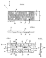
- 1 to 5 is a block bridge which has on its underside 15 a plurality of support webs 23, 23 'which are arranged parallel to the longitudinal edges.
- the support webs 23 closest to the longitudinal edges are flush on the outside with the longitudinal edge 17.
- the support webs 23 'parallel to these support webs 23' are arranged at a distance sa and form in the region of the end edges 22 inlet funnels 30 which are connected to one another by a water passage channel 31, so that, for example, condensation water is not prevented from flowing out by the presence of a block bridge .
- the longitudinal webs 23, 23 ' are parallel and symmetrical to the longitudinal axis 26.
- the construction of the support part 10 is stiffened by transverse webs 24, which connect the longitudinal webs 23, 23 'to one another.
- the curvatures 18, 18 ' are designed such that they are oriented transversely to the longitudinal axis 26 of the support part 10. This orientation has the advantage that the support member 10 can be pushed under pressure between the frame and the glazing without a sharp protruding edge of a curvature 18, 18 'could hinder this insertion by hooking onto an edge of the glazing.
- the curvature 18, 18 ' it is connected to two flexible curvature edge sections 21 which lie diametrically opposite one another and extend transversely to the longitudinal axis 26.
- the special design of such curved edge sections 21 can be found, for example, in German utility model 91 08 808.
- each longitudinal edge 17 is arranged or assigned two resiliently projecting curvatures 18 or 18'.
- All four arches 18, 18 ' are arranged symmetrically to one another, that is to say with respect to the longitudinal axis 26 and transversely thereto.
- Their curvature length wl which is measured transversely to the longitudinal axis 26, corresponds approximately to the distance sa between two support webs 23, 23 'parallel to the longitudinal edges. The arch length wl is thus less than half the plate width pb.
- the entire distance sa between the webs 23, 23 ' can be used to form the arches 18, 18', whereby it should be noted that the material thickness in the area of the arches 18, 18 'due to the required flexibility of the arch edge sections 21 and the elasticity of the curvature 18, 18 'is in each case smaller than the thickness of the plate 14.
- the arrangement of the curvatures 18, 18 'from the end edges 22 is at a distance a, which in the case of the embodiment according to FIGS. 1 to 5 is dimensioned such that the curvatures 18, 18' are not arranged in the region of the funnel 30.
- the curvatures 18, 18 ' are arranged at a distance wa from an adjacent transverse web 24, this distance wa ensuring that the function of the curvature 18, 18' is not impaired.
- FIG. 6 shows the underside of a support part 11, which is also provided with curvatures 18, but which overlap extend the entire width pb.
- the special feature of this support part 11 is its consistently lattice-like structure of the underside 15 of the plate 14, which is why this support part 11 can be referred to as a lattice block. In such a lattice block there is therefore no longitudinal channel. Rather, longitudinal webs 23, 23 'and transverse webs 15 form a closed grid over the entire plate width pb.
- this grid the webs of which are all of the same height and thus serve to support the frame surface, consists in the fact that the distance sa between the support webs 23, 23 'adjacent to one longitudinal edge 17 and in a certain relation to the distance sb of the two Support webs 23 'is set, which are adjacent to the longitudinal axis 26.
- the sum of the distances sa is namely smaller than the distance sb between the webs 23 '.
- This forms a special grid, the load capacity of which is particularly large in the region of the longitudinal edges 17. On the other hand, this results in a corresponding material saving in the area of the longitudinal axis that has no longitudinal webs.
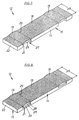
- the bulges 19 are each designed so that they have approximately a sector-shaped cross section. As a result, its resilient bulge edge portion 21 is located there where the curvature 19 merges into the non-curved plate 14. These curvature edge sections 21 extend over the entire plate width pb.
- the curvature edge sections 21 presuppose a sufficient weakening of the plate thickness 14, that is to say a groove 27 or a slot 28.
- the groove 27 is a transverse groove which extends over the entire plate width pb. The weakening of the plate thickness or the depth of the transverse groove 27 is so great that the curvature edge in the area of its section 21 is smaller than the maximum curvature thickness.
- the groove bottom 29 of the transverse slot 27 is flat.
- the same also applies to the transverse slot 28, which has a plate bottom 33 closing on the frame side.
- the plate bottom 33 is of the same thickness everywhere, so that a rectangular cross section of the transverse slot 28 arises as a result of the flat groove bottom 29.
- the supporting part 13 is overall slightly stiffer than the supporting part 12.
- the supporting part 13 can apply greater clamping forces.
- the underside 15 of the support parts 12, 13 can expediently be formed.
- An embodiment according to FIG. 4 or FIG. 6 is conceivable, the webs 23, 23 'having to be omitted in the areas of the arches 19 in order to ensure their flexibility.
- the curvatures 19 are arranged adjacent to the end edges 22 in both support parts 12, 13 of FIGS. 7, 8. Each support part 12, 13 thus has two curvatures 19. There is a correspondingly symmetrical design, combined with a correspondingly doubled clamping force, namely compared to a support part with a single curvature 19.
Landscapes
- Engineering & Computer Science (AREA)
- Civil Engineering (AREA)
- Structural Engineering (AREA)
- Securing Of Glass Panes Or The Like (AREA)
- Packaging Frangible Articles (AREA)
- Re-Forming, After-Treatment, Cutting And Transporting Of Glass Products (AREA)
Abstract
Description
- Die Erfindung bezieht sich auf ein Abstützteil für Glasscheiben von Fenstern, Türen od.dgl., das im wesentlichen als Platte ausgebildet ist, deren Unterseite auf einer Rahmenfläche aufliegt, deren Oberseite die Verglasung od.dgl. abstützt, und die mindestens eine aus der Plattenebene glasseitig federnd vorspringende, quer zu einer Plattenlängskante gerichtete Wölbung aufweist, die allseitig durchbrechungsfrei mit der Platte über einen zumindest an einer Wölbungskante nachgiebigen Wölbungskantenabschnitt verbunden ist.
- Ein Abstützteil mit den vorgenannten Merkmalen ist aus dem Deutschen Gebrauchsmuster 91 08 808 bekannt. Die bekannte Wölbung erstreckt sich quer zur Platte von einer Längskante zur anderen. Wenn die abzustützende Verglasung eine Isolierglasscheibe ist, werden deren beide Glasscheiben von einer einzigen Wölbung beaufschlagt, und zwar bei der üblicherweise vorhandenen Anpassung der Breite des Abstützteils an die Isolierglasscheibe von längskantennahen Wölbungsbereichen. Die längskantennahen Wölbungsbereiche springen von der Plattenoberseite aus weniger weit vor, als der dazwischen gelegene mittlere Wölbungsbereich. Dieser am weitesten vorspringende mittlere Wölbungsbereich wäre am ehesten geeignet, direkt auf die Verglasung zu drücken, und zwar mit der durch die konstruktive Auslegung des Abstützteils vorgesehenen Kraft. Der am weitesten vorspringende mittlere Wölbungsbereich ist auch am ehesten geeignet, einen größeren Abstand zwischen der Oberseite des Abstützteils und der Verglasung zu überbrücken, wenn ein solcher aufgrund der gegebenen Bautoleranzen vorhanden ist oder sich etwa im Laufe der Handhabung von Fensterrahmen und Verglasung einstellt, etwa während des Einbaus der Verglasung in den Fensterrahmen. Das bekannte Abstützteil muß daher so ausgelegt werden, daß auch noch die kantennahen Wölbungsbereiche die von der Konstruktion her erforderlichen Klemmkräfte aufbringen und Distanzen überbrücken kann. Das bedeutet eine vergleichsweise überdimensionierte Ausgestaltung des bekannten Abstützteils im Bereich der vorspringenden Wölbung. Insoweit ist dieses bekannte Abstützteil noch verbesserungsfähig.
- Der Erfindung liegt die Aufgabe zugrunde, ein Abstützteil mit den eingangs genannten Merkmalen so zu verbessern, daß es vorteilhaft im Hinblick auf längskantenseitig aufsitzende Glasscheiben ausgebildet ist.
- Diese Aufgabe wird dadurch gelöst, daß die Platte nahe jeder Längskante mindestens eine federnd vorspringende Wölbung aufweist, deren quer zur Plattenlängskante gemessene Wölbungslänge kleiner als die halbe Plattenbreite ist.
- Für die Erfindung ist von Bedeutung, daß das Abstützteil im Hinblick auf eine gezielte Abstützung der Glasscheiben einer Isolierglasscheibe besser ausgebildet wird. Infolge der Anordnung einer Wölbung nahe einer Plattenlängskante ist gewährleistet, daß sich die Glasscheibe auf der üblicherweise direkt benachbarten maximalen Wölbung abstützt. Daher ist ein optimaler Klemmeffekt gesichert, und zwar auch dann, wenn der infolge der Bautoleranzen vorhandene Abstand zwischen dem Abstützteil und der Isolierglasscheibe im Bereich der betroffenen Wölbung etwas größer sein sollte, als an sich vorgesehen. Infolge der geringen Wölbungslänge ist die Wölbung bei herkömmlicher Ausbildung auch steifer. Sie kann daher tragfähiger bzw. klemmkräftiger ausgebildet werden. Nicht zuletzt ist das Abstützteil bzw. deren Wölbung auch haltbarer, weil letztere spezieller auf die Belastungsaufgaben abgestimmt werden kann, nämlich auf die Abstützung einer einzigen Glasscheibe.
- Vorteilhafterweise wird das Abstützteil so ausgebildet, daß es nahe jeder Plattenlängskante zwei federnd vorspringende Wölbungen aufweist, und daß eine Wölbung einer Längskante und eine Wölbung der anderen Längskante denselben Abstand von einer Stirnkante der Platte haben. Es wird also eine Doppelabstützung jeder Glasscheibe einer Isolierglasscheibe vorgesehen. Insgesamt wird jede Glasscheibe einer Isolierglasscheibe doppelt abgestützt. Die doppelte Abstützung jeder Glasscheibe gewährleistet infolge der Bildung zweier Klemmstellen doppelte Sicherheit. Die symmetrische Anordnung aller Wölbungen trägt dazu bei, daß Zweifel über die richtige Einbaulage nicht aufkommen können. Eine vorteilhafte Ausgestaltung des Abstützteils ist gegeben, wenn an der Plattenunterseite nahe jeder Längskante zwei längskantenparallele Abstützstege mit Abstand zueinander angeordnet sind, und wobei die Wölbungslänge etwa gleich dem Abstand der Abstützstege voneinander ist. Es herrscht dann eine vollständige Freizügigkeit bei der Ausbildung der Wölbungen trotz des Vorhandenseins der parallelen Abstützstege auf der Plattenunterseite.
- Sofern die vorbeschriebenen Abstützstege an der Plattenunterseite in Abständen durch Querstege miteinander verbunden sind, wird eine Ausgestaltung des Abstützteils bevorzugt, bei dem die Wölbungen in Bezug auf zwischen den Abstützstegen vorhandene Querstege mit Abstand zu letzteren angeordnet sind. Hierdurch ergibt sich die erforderliche Freiheit bei der Ausbildung der Wölbungen in deren seitlicher Richtung, also in Längsrichtung des Abstützteils. Insbesondere kann die Breite der Wölbungen in diesen Richtungen frei gewählt werden, ohne durch die Ausbildung der Abstützstege der Plattenunterseite beeinträchtigt zu sein.
- Eine besondere Ausgestaltung eines Abstützteils, welche nicht notwendigerweise die vorbeschriebenen Merkmale der Wölbung bzw. der Wölbungen der Platte aufweisen muß und auch überhaupt keine Wölbungen aufzuweisen braucht, ist dadurch gekennzeichnet, daß an der Plattenunterseite längskantenparallele Abstützstege und diese miteinander verbindende, gleich hohe Querstege angeordnet sind, und daß der Abstand zwischen den beiden der Längsachse benachbarten, längskantenparallelen Abstützstegen größer ist, als die Summe der Abstände zwischen dem längskantennächsten und dem letzterem benachbarten Abstützsteg. Die auf der Plattenunterseite vorhandenen Abstützstege bilden ein Gitter, welches einen beträchtlichen Materialaufwand darstellt. Bei den bekannten Abstützteilen bzw. Gitterklötzen erstreckt sich dieses Gitter gleichförmig über die gesamte Breite und über die gesamte Länge des Abstützteils. Um die Masse der Abstützteile zu reduzieren, also die beim Spritzgießen erforderliche Kunststoffmasse, wird durch die neue Ausgestaltung des Abstützteils dafür gesorgt, daß die gitterförmige Ausgestaltung im wesentlichen nur im Bereich der Plattenlängskanten des Abstützteils vorhanden sind. Hier sind die Belastungen durch die Glasscheiben einer Isolierglasscheibe am größten. In der Mitte zwischen den Längskanten wird ein weiterer längskantenparalleler Abstützsteg weniger benötigt. Es ergibt sich daher die vorteilhafte Möglichkeit, daß Abstützteil im wesentlichen wie vorbeschrieben zu dimensionieren, also mit einem breiten, längsabstützstegfreien Bereich.
- Des weiteren bezieht sich die Erfindung auf ein Abstützteil für Glasscheiben von Fenstern, Türen od.dgl., das im wesentlichen als Platte ausgebildet ist, deren Unterseite auf einer Rahmenfläche aufliegt und deren Oberseite die Verglasung od.dgl. abstützt sowie mindestens eine aus der Plattenebene glasseitig federnd vorspringende Wölbung aufweist, die allseitig durchbrechungsfrei mit der Platte über einen zumindest an einer Wölbungskante nachgiebigen Wölbungskantenabschnitt verbunden ist. Auch ein derartiges Abstützteil, das aus dem Deutschen Gebrauchsmuster 91 08 808 bekannt ist, läßt sich hinsichtlich der Wirkung seiner Wölbungen im Sinne der oben genannten Aufgabenstellung verbessern. Eine solche Verbesserung wird dadurch erreicht, daß die Platte unterseitig mindestens einen sich über die gesamte Plattenbreite erstreckenden rahmenseitig geschlossenen Querschlitz und/oder eine sich über die gesamte Plattenbreite erstreckende rahmenseitig offene Quernut aufweist, die mit der parallel zu den Längskanten orientierten Wölbung den nachgiebigen Wölbungskantenabschnitt bildet bzw. bilden. Bei dem vorgenannten Abstützteil ist von Bedeutung, daß sich dessen Wölbung parallel zu den Längskanten orientiert. Die Wölbung kann infolgedessen vorteilhafterweise so ausgestaltet werden, daß ihre Querschnitte bzw. Schnitte durch die Wölbung quer zu den Längskanten stets gleiche Wölbungshöhe in Relation zur Isolierglasscheibe haben. Es spielt infolgedessen keine Rolle, an welcher Stelle einer Wölbung die Isolierglasscheibe bzw. ihre beiden Glasscheiben auf das Abstützteil drücken. Stets wird die maximale Wölbung des Abstützteils beaufschlagt. Die Wölbung eines Abstützteils kann auch vergleichsweise robust ausgebildet werden, so daß sich entsprechend starke Klemmkräfte erzielen lassen. Im Falle einer rahmenseitig offenen Quernut kann eine starke Beaufschlagung der Wölbung zu einer geringfügigen Längung des Abstützteils führen, wobei durch die Längung die spezifische Materialbeanspruchung im nachgiebigen Wölbungskantenabschnitt klein gehalten werden kann. Für demgegenüber noch weiter wesentlich erhöhte Klemmkräfte empfiehlt sich die Ausbildung des Abstützteils mit dem rahmenseitig geschlossenen Querschlitz, wobei die im Bereich des Querschlitzes vorhandene rahmenseitige Auflagefläche des Abstützteils dessen Versteifung bewirkt.
- Zweckmäßigerweise hat die Wölbung einen ebenen Querschlitz- oder Nutenboden. Es ergibt sich eine im wesentlichen sektorförmige Querschnittsgestaltung bei einem plattenlängskantenparallelen Schnitt durch das Abstützteil. Der Wölbungskantenabschnitt erstreckt sich über die gesamte zwischen den Plattenlängskanten vorhandene Breite des Abstützteils in gleicher baulicher Ausgestaltung.
- Um eine symmetrische Ausgestaltung des Abstützteils zu erreichen, bei der insbesondere auch kein Zweifel über die Anordnung des Abstützteils auf der Rahmenfläche besteht, wird das Abstützteil so ausgebildet, daß je eine Wölbung einer Stirnkante benachbart ist.
- Die Erfindung wird anhand von in der Zeichnung dargestellten Ausführungsbeispielen erläutert. Es zeigt:
- Fig.1
- eine perspektivische Ansicht einer ersten Ausführungsform eines erfindungsgemäßen Abstützteils,
- Fig.2
- eine Aufsicht des Ausführungsbeispiels der Fig.1,
- Fig.3
- eine Seitenansicht des Abstützteils der Fig.2 in Richtung A,
- Fig.4
- eine Unteransicht des Abstützteils der Fig.2,
- Fig.5
- eine Seitenansicht der Stirnseite des Abstützteils in Richtung B der Fig.4,
- Fig.6
- eine Unteransicht eines weiteren Abstützteils, und
- Fig.7,8
- perspektivische Ansichten weiterer Abstützteile.
- Die in den Figuren dargestellten Abstützteile 10 bis 13 bestehen im wesentlichen aus je einer Platte 14, die jeweils eine geschlossene bzw. durchbrechungsfreie Oberseite 16 hat, und deren Unterseite 15 den unterschiedlichen Erfordernissen entsprechend ausgebildet ist.
- Das Abstützteil der Fig.1 bis 5 ist eine Klotzbrücke, die an ihrer Unterseite 15 mehrere Abstützstege 23,23' hat, die längskantenparallel angeordnet sind. Die längskantennächsten Abstützstege 23 schließen außenseitig bündig mit der Längskante 17 ab. Die zu diesen Abstützstegen 23 parallelen Abstützstege 23' sind im Abstand sa angeordnet und bilden im Bereich der Stirnkanten 22 Einlauftrichter 30, die durch einen Wasserdurchtrittskanal 31 miteinander verbunden sind, so daß beispielsweise durch Kondensation anfallendes Wasser durch das Vorhandensein einer Klotzbrücke nicht am Abströmen gehindert wird. Die Längsstege 23,23' sind parallel und symmetrisch zur Längsachse 26 ausgebildet. Die Konstruktion des Abstützteils 10 wird durch Querstege 24 versteift, welche die Längsstege 23,23' miteinander verbinden.
- Um das Abstützteil 10 zwischen einer Rahmenfläche eines Fensterrahmens od.dgl. einerseits und einer Verglasung des Fensters andererseits festsetzen zu können, wodurch die Verglasung innerhalb des Fensterrahmens ordnungsgemäß abgestützt wird, sind in der Platte 14 des Abstützteils 10 Wölbungen 18, 18' vorhanden. Die Wölbungen 18,18' sind insgesamt nachgiebig, so daß sie von einer auf ihnen ruhenden Verglasung zusammengedrückt werden. Die Fig.3,5 zeigen den Vorsprung der Wölbungen 18 in nicht durch eine Verglasung komprimiertem Zustand und es ist ersichtlich, daß ihr Überstand 32 z.B. 1,5 mm betragen kann und damit genügend groß ist, um Bautoleranzen auszugleichen und erforderliche Klemmkräfte zu erzeugen.
- Die Wölbungen 18,18' sind so ausgebildet, daß sie quer zur Längsachse 26 des Abstützteils 10 orientiert sind. Diese Orientierung hat den Vorteil, daß das Abstützteil 10 unter Druckanwendung zwischen den Rahmen und die Verglasung geschoben werden kann, ohne daß eine scharf vorspringende Kante einer Wölbung 18,18' dieses Einschieben behindern könnte, indem sie an einer Kante der Verglasung festhakt. Um die Nachgiebigkeit der Wölbung 18,18' zu erreichen, ist diese mit zwei nachgiebigen Wölbungskantenabschnitten 21 verbunden, die einander diametral gegenüberliegen und sich quer zur Längsachse 26 erstrecken. Die spezielle Ausbildung solcher Wölbungskantenabschnitte 21 kann beispielsweise dem Deutschen Gebrauchsmuster 91 08 808 entnommen werden.
- Im Abstützteil 10 ist die spezielle Anordnung der Wölbungen 18,18' so getroffen, daß jeder Längskante 17 zwei federnd vorspringende Wölbungen 18 oder 18' benachbart angeordnet bzw. zugeordnet sind. Alle vier Wölbungen 18,18' sind symmetrisch zueinander angeordnet, also bezogen auf die Längsachse 26 und quer dazu. Ihre Wölbungslänge wl, die quer zur Längsachse 26 gemessen wird, entspricht etwa dem Abstand sa zweier längskantenparalleler Abstützstege 23,23'. Damit ist die Wölbungslänge wl kleiner als die halbe Plattenbreite pb. Durch diese Bemessung kann der gesamte Abstand sa zwischen den Stegen 23,23' zur Ausbildung der Wölbungen 18,18' ausgenutzt werden, wobei zu beachten ist, daß die Werkstoffdicke im Bereich der Wölbungen 18,18' infolge der erforderlichen Nachgiebigkeit der Wölbungskantenabschnitte 21 und der Elastizität der Wölbung 18, 18' jeweils kleiner ist, als die Dicke der Platte 14.
- Die Anordnung der Wölbungen 18,18' von den Stirnkanten 22 weist den Abstand a auf, der im Falle der Ausbildung gemäß den Fig.1 bis 5 so bemessen ist, daß die Wölbungen 18,18' nicht im Bereich der Trichter 30 angeordnet sind. Außerdem sind die Wölbungen 18,18' in einem Abstand wa von einem benachbarten Quersteg 24 angeordnet, wobei dieser Abstand wa gewährleistet, daß die Funktion der Wölbung 18,18' nicht beeinträchtigt wird.
- Fig.6 zeigt die Unterseite eines Abstützteils 11, welches ebenfalls mit Wölbungen 18 versehen ist, die sich jedoch über die gesamte Breite pb erstrecken. Die Besonderheit dieses Abstützteils 11 ist seine durchweg gitterartige Struktur der Unterseite 15 der Platte 14, weswegen dieses Abstützteil 11 als Gitterklotz bezeichnet werden kann. Bei einem derartigen Gitterklotz ist also kein längsdurchlaufender Kanal vorhanden. Vielmehr bilden Längsstege 23,23' und Querstege 15 ein über die gesamte Plattenbreite pb geschlossenes Gitter. Die Besonderheit dieses Gitters, dessen Stege alle gleich hoch ausgebildet sind und damit der Abstützung auf der Rahmenfläche dienen, besteht darin, daß der Abstand sa zwischen den einer Längskante 17 benachbarten längskantenparallelen Abstützstegen 23,23' in eine bestimmte Relation zu dem Abstand sb derjenigen beiden Abstützstege 23' gesetzt ist, die der Längsachse 26 benachbart sind. Die Summe der Abstände sa ist nämlich kleiner, als der Abstand sb zwischen den Stegen 23'. Dadurch wird ein spezielles Gitter ausgebildet, dessen Tragfähigkeit im Bereich der Längskanten 17 besonders groß ist. Andererseits ergibt sich daraus eine entsprechende Materialeinsparung in demjenigen Bereich der Längsachse, der keine Längsstege aufweist.
- Die Fig.7,8 zeigen Ausgestaltungen von Abstützteilen 12, 13, die sich von den Ausbildungen der vorbeschriebenen Abstützteile 10,11 erheblich unterscheiden. Insbesondere ist von Bedeutung, daß beide Abstützteile 12,13 Wölbungen 19 aufweisen, die in Längsrichtung der Abstützteile orientiert sind. Andererseits erstrecken sich die Wölbungen 19 über die gesamte Plattenbreite pb. Die Ausbildung der Wölbungen 19 ist aber dergestalt, daß quer zur Längserstreckung der Abstützteile 12, 13 keine Wölbungen vorhanden ist. Querschnitte des Abstützteils im Wölbungsbereich ergeben also gleiche Höhen bzw. Plattendicken im gesamten Breitenbereich der Abstützteile 12,13. Es wird damit gewährleistet, daß die Verglasung unabhängig von ihrer relativen Positionierung in Bezug auf das Abstützteil 12,13 jeweils in gleichem Maße durch die Wölbung 19 beaufschlagt wird bzw. letztere zusammendrückt, so daß die Klemmkräfte jeweils gleich groß sind.
- Die Wölbungen 19 sind jeweils so ausgestaltet, daß sie etwa einen sektorförmigen Querschnitt aufweisen. Infolgedessen wird ihr nachgiebiger Wölbungskantenabschnitt 21 dort angeordnet, wo die Wölbung 19 in die ungewölbte Platte 14 übergeht. Diese Wölbungskantenabschnitte 21 erstrecken sich über die gesamte Plattenbreite pb.
- Die Wölbungskantenabschnitte 21 setzen eine ausreichende Schwächung der Plattendicke 14 voraus, also eine Nut 27 oder ein Schlitz 28. Die Nut 27 ist eine Quernut, die sich über die gesamte Plattenbreite pb erstreckt. Die Schwächung der Plattendicke bzw. die Tiefe der Quernut 27 ist so groß, daß die Wölbungskante im Bereich ihres Abschnitts 21 kleiner ist, als die maximale Wölbungsdicke. Der Nutenboden 29 des Querschlitzes 27 ist eben. Dasselbe gilt auch für den Querschlitz 28, die einen rahmenseitig verschließenden Plattenboden 33 hat. Der Plattenboden 33 ist überall gleich dick, so daß infolge des ebenen Nutenbodens 29 ein rechteckiger Querschnitt des Querschlitzes 28 entsteht.
- Infolge des Plattenbodens 33 ist das Abstützteil 13 insgesamt geringfügig steifer, als das Abstützteil 12. Das Abstützteil 13 kann größere Klemmkräfte aufzubringen.
- Die Unterseite 15 der Abstützteile 12,13 kann zweckmäßig ausgebildet werden. Denkbar ist eine Ausbildung gemäß Fig.4 oder Fig.6, wobei die Stege 23,23' in den Bereichen der Wölbungen 19 entfallen müssen, um deren Nachgiebigkeit zu gewährleisten.
- Die Wölbungen 19 sind in beiden Abstützteilen 12,13 der Fig.7,8 den Stirnkanten 22 benachbart angeordnet. Jedes Abstützteil 12,13 hat also zwei Wölbungen 19. Es liegt eine entsprechend symmetrische Ausbildung vor, kombiniert mit entsprechend verdoppelter Klemmkraft, nämlich gegenüber einem Abstützteil mit einer einzigen Wölbung 19.
Claims (8)
- Abstützteil (10 bis 13) für Glasscheiben von Fenstern, Türen od.dgl., das im wesentlichen als Platte (14) ausgebildet ist, deren Unterseite (15) auf einer Rahmenfläche aufliegt, deren Oberseite (16) die Verglasung od.dgl. abstützt, und die mindestens eine aus der Plattenebene glasseitig federnd vorspringende, quer zu einer Plattenlängskante (17) gerichtete Wölbung (18,18') aufweist, die allseitig durchbrechungsfrei mit der Platte (14) über einen zumindest an einer Wölbungskante (20) nachgiebigen Wölbungskantenabschnitt (21) verbunden ist, dadurch gekennzeichnet, daß die Platte (14) nahe jeder Längskante (17) mindestens eine federnd vorspringende Wölbung (18, 18') aufweist, deren quer zur Plattenlängskante (17) gemessene Wölbungslänge (wl) kleiner als die halbe Plattenbreite (pb) ist.
- Abstützteil nach Anspruch 1, dadurch gekennzeichnet, daß es nahe jeder Plattenlängskante (17) zwei federnd vorspringende Wölbungen (18 oder 18') aufweist, und daß eine Wölbung (18) einer Längskante (17) und eine Wölbung (18') der anderen Längskante (17) denselben Abstand (a) von einer Stirnkante (22) der Platte (14) haben.
- Abstützteil nach Anspruch 1 oder 2, dadurch gekennzeichnet, daß an der Plattenunterseite (15) nahe jeder Längskante (17) zwei längskantenparallele Abstützstege (23,23') mit Abstand (sa) zueinander angeordnet sind, und daß die Wölbungslänge (wl) etwa gleich dem Abstand (sa) der Abstützstege (23,23') voneinander ist.
- Abstützteil nach einem oder mehreren der Ansprüche 1 bis 3, dadurch gekennzeichnet, daß die Wölbungen (18,18') in Bezug auf zwischen den Abstützstegen (23,23') vorhandene Querstege (24) mit Abstand (wa) zu letzteren angeordnet sind.
- Abstützteil insbesondere nach einem oder mehreren der Ansprüche 1 bis 4, dadurch gekennzeichnet, daß an der Plattenunterseite (15) längskantenparallele Abstützstege (23,23') und diese miteinander verbindende, gleich hohe Querstege (25) angeordnet sind, und daß der Abstand (sb) zwischen den beiden der Längsachse (26) benachbarten, längskantenparallelen Abstützstegen (23') größer ist, als die Summe der Abstände (sa) zwischen dem längskantennächsten (23) und dem letzterem (23') benachbarten Abstützsteg.
- Abstützteil (12,13) für Glasscheiben von Fenstern, Türen od.dgl., das im wesentlichen als Platte (14) ausgebildet ist, deren Unterseite (15) auf einer Rahmenfläche aufliegt und deren Oberseite (16) die Verglasung od.dgl. abstützt sowie mindestens eine aus der Plattenebene glasseitig federnd vorspringende Wölbung (19) aufweist, die allseitig durchbrechungsfrei mit der Platte (14) über einen zumindest an einer Wölbungskante (20) nachgiebigen Wölbungskantenabschnitt (21) verbunden ist, dadurch gekennzeichnet, daß die Platte (14) unterseitig mindestens einen sich über die gesamte Plattenbreite (pb) erstreckenden rahmenseitig geschlossenen Querschlitz (27) und/oder eine sich über die gesamte Plattenbreite (pb) erstreckende rahmenseitig offene Quernut (28) aufweist, die mit der parallel zu den Längskanten (17) orientierten Wölbung (19) den nachgiebigen Wölbungskantenabschnitt bildet bzw. bilden.
- Abstützteil nach Anspruch 6, dadurch gekennzeichnet, daß die Wölbung (19) einen ebenen Querschlitz- oder Nutenboden (29) hat.
- Abstützteil nach Anspruch 6 oder 7, dadurch gekennzeichnet, daß je eine Wölbung (19) einer Stirnkante (22) benachbart ist.
Applications Claiming Priority (2)
| Application Number | Priority Date | Filing Date | Title |
|---|---|---|---|
| DE4239735 | 1992-11-26 | ||
| DE4239735A DE4239735A1 (de) | 1992-11-26 | 1992-11-26 | Abstützteil für Glasscheiben von Fenstern, Türen o. dgl. |
Publications (2)
| Publication Number | Publication Date |
|---|---|
| EP0599051A1 true EP0599051A1 (de) | 1994-06-01 |
| EP0599051B1 EP0599051B1 (de) | 1998-01-21 |
Family
ID=6473691
Family Applications (1)
| Application Number | Title | Priority Date | Filing Date |
|---|---|---|---|
| EP93116913A Expired - Lifetime EP0599051B1 (de) | 1992-11-26 | 1993-10-20 | Abstützteil für Glasscheiben von Fenstern, Türen od. dgl. |
Country Status (5)
| Country | Link |
|---|---|
| EP (1) | EP0599051B1 (de) |
| AT (1) | ATE162586T1 (de) |
| DE (2) | DE4239735A1 (de) |
| DK (1) | DK0599051T3 (de) |
| ES (1) | ES2112371T3 (de) |
Cited By (5)
| Publication number | Priority date | Publication date | Assignee | Title |
|---|---|---|---|---|
| EP0716206A3 (de) * | 1994-12-10 | 1996-11-20 | Niemann Hans Dieter | Klotz zur Abstützung von Glasscheiben in Tür- oder Fensterrahmen und Verfahren zum Zusammenbau eines Tür- oder Fensterrahmens mit einer Glasscheibe |
| WO1999033378A1 (en) * | 1997-12-24 | 1999-07-08 | Keith John Nurcombe | Panel and frame arrangement |
| EP2017426A2 (de) | 2006-04-07 | 2009-01-21 | Simon Christopher Braid | Fensterverglasungseinheitmontageanordnung |
| GB2547911A (en) * | 2016-03-02 | 2017-09-06 | Christopher Braid Simon | A packing element for a panel |
| CN110271737A (zh) * | 2019-08-06 | 2019-09-24 | 宁波丽成超级树脂有限公司 | 一种柔性液晶玻璃面板处理装置用碳纤维复合平板 |
Families Citing this family (3)
| Publication number | Priority date | Publication date | Assignee | Title |
|---|---|---|---|---|
| DE29709017U1 (de) * | 1997-05-22 | 1998-09-24 | Niemann, Hans Dieter, 50169 Kerpen | Verglasungsklotz |
| CN106829479B (zh) * | 2017-03-25 | 2022-05-13 | 广东高力威机械科技有限公司 | 立式玻璃检测输送台及其检测方法 |
| DE102017223068A1 (de) * | 2017-12-18 | 2019-07-11 | Adolf Würth Gmbh & Co Kg | Montageklotz |
Citations (5)
| Publication number | Priority date | Publication date | Assignee | Title |
|---|---|---|---|---|
| US2617159A (en) * | 1949-10-13 | 1952-11-11 | Libbey Owens Ford Glass Co | Mounting device for glazing units |
| US2723427A (en) * | 1952-12-04 | 1955-11-15 | Pittsburgh Plate Glass Co | Multiple glazed window glazing clip |
| WO1984000574A1 (en) * | 1982-07-30 | 1984-02-16 | Lars Erik Eriksson | Elements for supporting and bracing sealed-glazing units |
| DE9108808U1 (de) * | 1991-07-17 | 1991-09-12 | Niemann, Hans Dieter, 5014 Kerpen | Abstützteil für Glasscheiben von Fenstern, Türen o.dgl. |
| DE9116399U1 (de) * | 1991-07-11 | 1992-09-17 | Deflex-Dichtsysteme GmbH, 4100 Duisburg | Glasklotzbrücke |
-
1992
- 1992-11-26 DE DE4239735A patent/DE4239735A1/de not_active Withdrawn
-
1993
- 1993-10-20 ES ES93116913T patent/ES2112371T3/es not_active Expired - Lifetime
- 1993-10-20 AT AT93116913T patent/ATE162586T1/de active
- 1993-10-20 DK DK93116913T patent/DK0599051T3/da active
- 1993-10-20 DE DE59308037T patent/DE59308037D1/de not_active Expired - Fee Related
- 1993-10-20 EP EP93116913A patent/EP0599051B1/de not_active Expired - Lifetime
Patent Citations (5)
| Publication number | Priority date | Publication date | Assignee | Title |
|---|---|---|---|---|
| US2617159A (en) * | 1949-10-13 | 1952-11-11 | Libbey Owens Ford Glass Co | Mounting device for glazing units |
| US2723427A (en) * | 1952-12-04 | 1955-11-15 | Pittsburgh Plate Glass Co | Multiple glazed window glazing clip |
| WO1984000574A1 (en) * | 1982-07-30 | 1984-02-16 | Lars Erik Eriksson | Elements for supporting and bracing sealed-glazing units |
| DE9116399U1 (de) * | 1991-07-11 | 1992-09-17 | Deflex-Dichtsysteme GmbH, 4100 Duisburg | Glasklotzbrücke |
| DE9108808U1 (de) * | 1991-07-17 | 1991-09-12 | Niemann, Hans Dieter, 5014 Kerpen | Abstützteil für Glasscheiben von Fenstern, Türen o.dgl. |
Cited By (6)
| Publication number | Priority date | Publication date | Assignee | Title |
|---|---|---|---|---|
| EP0716206A3 (de) * | 1994-12-10 | 1996-11-20 | Niemann Hans Dieter | Klotz zur Abstützung von Glasscheiben in Tür- oder Fensterrahmen und Verfahren zum Zusammenbau eines Tür- oder Fensterrahmens mit einer Glasscheibe |
| WO1999033378A1 (en) * | 1997-12-24 | 1999-07-08 | Keith John Nurcombe | Panel and frame arrangement |
| GB2332694B (en) * | 1997-12-24 | 2002-10-30 | Keith John Nurcombe | Panel and frame arrangement |
| EP2017426A2 (de) | 2006-04-07 | 2009-01-21 | Simon Christopher Braid | Fensterverglasungseinheitmontageanordnung |
| GB2547911A (en) * | 2016-03-02 | 2017-09-06 | Christopher Braid Simon | A packing element for a panel |
| CN110271737A (zh) * | 2019-08-06 | 2019-09-24 | 宁波丽成超级树脂有限公司 | 一种柔性液晶玻璃面板处理装置用碳纤维复合平板 |
Also Published As
| Publication number | Publication date |
|---|---|
| ES2112371T3 (es) | 1998-04-01 |
| ATE162586T1 (de) | 1998-02-15 |
| DE4239735A1 (de) | 1994-06-01 |
| DE59308037D1 (de) | 1998-02-26 |
| DK0599051T3 (da) | 1998-09-14 |
| EP0599051B1 (de) | 1998-01-21 |
Similar Documents
| Publication | Publication Date | Title |
|---|---|---|
| EP0304539A1 (de) | Schaltbrücke für elektrische Schaltgeräte, insbesondere Schütze | |
| EP1235990A1 (de) | Führungsschiene für ein linearlager | |
| DE9216955U1 (de) | Steckverbinder für Hohlprofile | |
| EP0114220B1 (de) | Klotzbrücke zum Festsetzen von Glasscheiben od. dgl. in Tür- oder Fensterrahmen | |
| EP0599051B1 (de) | Abstützteil für Glasscheiben von Fenstern, Türen od. dgl. | |
| EP0315936B1 (de) | Klotzteil zum Festsetzen von Glasscheiben od. dgl. | |
| CH632049A5 (de) | Zur stuetzung eines randes eines plattenfoermigen koerpers, insbesondere einer isolierglastafel, bestimmtes element. | |
| EP0523282B1 (de) | Abstützteil für Glasscheiben von Fenstern, Türen od. dgl. | |
| DE3235026C2 (de) | ||
| EP0149443A2 (de) | Klemmverbindung zwischen einer Doppelstegplatte und einem Profil, insbesondere bei Kleingewächshäusern | |
| DE19822291C2 (de) | Glasfalzeinlage | |
| EP0400374B1 (de) | Einrichtung zur Verklotzung von Scheiben in Tür- oder Fensterrahmen | |
| DE1810483B2 (de) | Versetzbare Trennwand mit Profil pfosten | |
| DE2606614A1 (de) | Rahmen fuer einen fenster- oder tuerfluegel | |
| DE10044192C1 (de) | Glasfalzeinlage | |
| EP0687790A1 (de) | Linearverbinder für hohle Abstandsprofile eines Mehrscheibenisolierglases | |
| DE3414958A1 (de) | Verklotzungssystem | |
| DE9217883U1 (de) | Klotzteil zum Festsetzen von Glasscheiben o.dgl. in Nuten von Tür- oder Fensterrahmen | |
| EP0698308B1 (de) | Unterteil für einen installationskanal | |
| DE4041811A1 (de) | Federschiene | |
| DE3231600A1 (de) | Aluminium-fensterbank | |
| DE29808988U1 (de) | Glasfalzeinlage | |
| EP0755479B1 (de) | Verglasungsklotz | |
| DE7702843U1 (de) | Fuehrungsschiene | |
| DE3942060C2 (de) | Abstandhalter |
Legal Events
| Date | Code | Title | Description |
|---|---|---|---|
| PUAI | Public reference made under article 153(3) epc to a published international application that has entered the european phase |
Free format text: ORIGINAL CODE: 0009012 |
|
| AK | Designated contracting states |
Kind code of ref document: A1 Designated state(s): AT BE CH DE DK ES FR GB IT LI NL |
|
| 17P | Request for examination filed |
Effective date: 19941123 |
|
| 17Q | First examination report despatched |
Effective date: 19960430 |
|
| GRAG | Despatch of communication of intention to grant |
Free format text: ORIGINAL CODE: EPIDOS AGRA |
|
| GRAG | Despatch of communication of intention to grant |
Free format text: ORIGINAL CODE: EPIDOS AGRA |
|
| GRAH | Despatch of communication of intention to grant a patent |
Free format text: ORIGINAL CODE: EPIDOS IGRA |
|
| GRAH | Despatch of communication of intention to grant a patent |
Free format text: ORIGINAL CODE: EPIDOS IGRA |
|
| GRAA | (expected) grant |
Free format text: ORIGINAL CODE: 0009210 |
|
| AK | Designated contracting states |
Kind code of ref document: B1 Designated state(s): AT BE CH DE DK ES FR GB IT LI NL |
|
| REF | Corresponds to: |
Ref document number: 162586 Country of ref document: AT Date of ref document: 19980215 Kind code of ref document: T |
|
| REG | Reference to a national code |
Ref country code: CH Ref legal event code: EP |
|
| REG | Reference to a national code |
Ref country code: CH Ref legal event code: NV Representative=s name: E. BLUM & CO. PATENTANWAELTE |
|
| REF | Corresponds to: |
Ref document number: 59308037 Country of ref document: DE Date of ref document: 19980226 |
|
| ET | Fr: translation filed | ||
| REG | Reference to a national code |
Ref country code: ES Ref legal event code: FG2A Ref document number: 2112371 Country of ref document: ES Kind code of ref document: T3 |
|
| ITF | It: translation for a ep patent filed | ||
| GBT | Gb: translation of ep patent filed (gb section 77(6)(a)/1977) |
Effective date: 19980402 |
|
| REG | Reference to a national code |
Ref country code: DK Ref legal event code: T3 |
|
| PGFP | Annual fee paid to national office [announced via postgrant information from national office to epo] |
Ref country code: AT Payment date: 19980923 Year of fee payment: 6 |
|
| PGFP | Annual fee paid to national office [announced via postgrant information from national office to epo] |
Ref country code: CH Payment date: 19980929 Year of fee payment: 6 |
|
| PGFP | Annual fee paid to national office [announced via postgrant information from national office to epo] |
Ref country code: DE Payment date: 19981015 Year of fee payment: 6 |
|
| PG25 | Lapsed in a contracting state [announced via postgrant information from national office to epo] |
Ref country code: GB Free format text: LAPSE BECAUSE OF NON-PAYMENT OF DUE FEES Effective date: 19981020 Ref country code: DK Free format text: LAPSE BECAUSE OF NON-PAYMENT OF DUE FEES Effective date: 19981020 |
|
| PG25 | Lapsed in a contracting state [announced via postgrant information from national office to epo] |
Ref country code: ES Free format text: LAPSE BECAUSE OF NON-PAYMENT OF DUE FEES Effective date: 19981021 |
|
| PG25 | Lapsed in a contracting state [announced via postgrant information from national office to epo] |
Ref country code: BE Free format text: LAPSE BECAUSE OF NON-PAYMENT OF DUE FEES Effective date: 19981031 |
|
| PLBE | No opposition filed within time limit |
Free format text: ORIGINAL CODE: 0009261 |
|
| STAA | Information on the status of an ep patent application or granted ep patent |
Free format text: STATUS: NO OPPOSITION FILED WITHIN TIME LIMIT |
|
| 26N | No opposition filed | ||
| BERE | Be: lapsed |
Owner name: NIEMANN HANS-DIETER Effective date: 19981031 |
|
| PG25 | Lapsed in a contracting state [announced via postgrant information from national office to epo] |
Ref country code: NL Free format text: LAPSE BECAUSE OF NON-PAYMENT OF DUE FEES Effective date: 19990501 |
|
| GBPC | Gb: european patent ceased through non-payment of renewal fee |
Effective date: 19981020 |
|
| PG25 | Lapsed in a contracting state [announced via postgrant information from national office to epo] |
Ref country code: FR Free format text: LAPSE BECAUSE OF NON-PAYMENT OF DUE FEES Effective date: 19990630 |
|
| NLV4 | Nl: lapsed or anulled due to non-payment of the annual fee |
Effective date: 19990501 |
|
| REG | Reference to a national code |
Ref country code: FR Ref legal event code: ST |
|
| PG25 | Lapsed in a contracting state [announced via postgrant information from national office to epo] |
Ref country code: AT Free format text: LAPSE BECAUSE OF NON-PAYMENT OF DUE FEES Effective date: 19991020 |
|
| PG25 | Lapsed in a contracting state [announced via postgrant information from national office to epo] |
Ref country code: LI Free format text: LAPSE BECAUSE OF NON-PAYMENT OF DUE FEES Effective date: 19991031 Ref country code: CH Free format text: LAPSE BECAUSE OF NON-PAYMENT OF DUE FEES Effective date: 19991031 |
|
| REG | Reference to a national code |
Ref country code: CH Ref legal event code: PL |
|
| PG25 | Lapsed in a contracting state [announced via postgrant information from national office to epo] |
Ref country code: DE Free format text: LAPSE BECAUSE OF NON-PAYMENT OF DUE FEES Effective date: 20000801 |
|
| REG | Reference to a national code |
Ref country code: DK Ref legal event code: EBP |
|
| REG | Reference to a national code |
Ref country code: ES Ref legal event code: FD2A Effective date: 19991113 |
|
| PG25 | Lapsed in a contracting state [announced via postgrant information from national office to epo] |
Ref country code: IT Free format text: LAPSE BECAUSE OF NON-PAYMENT OF DUE FEES Effective date: 20051020 |