EP0597456B1 - Vorrichtung und Verfahren zum Verbinden eines Drahtes mit einem Kontaktelement - Google Patents
Vorrichtung und Verfahren zum Verbinden eines Drahtes mit einem Kontaktelement Download PDFInfo
- Publication number
- EP0597456B1 EP0597456B1 EP93118210A EP93118210A EP0597456B1 EP 0597456 B1 EP0597456 B1 EP 0597456B1 EP 93118210 A EP93118210 A EP 93118210A EP 93118210 A EP93118210 A EP 93118210A EP 0597456 B1 EP0597456 B1 EP 0597456B1
- Authority
- EP
- European Patent Office
- Prior art keywords
- crimping
- pressure
- contact element
- jaw
- punch
- Prior art date
- Legal status (The legal status is an assumption and is not a legal conclusion. Google has not performed a legal analysis and makes no representation as to the accuracy of the status listed.)
- Expired - Lifetime
Links
- 238000000034 method Methods 0.000 title claims description 6
- 238000002788 crimping Methods 0.000 claims abstract description 58
- 239000000463 material Substances 0.000 claims description 3
- 238000004146 energy storage Methods 0.000 claims 3
- 230000006835 compression Effects 0.000 abstract description 8
- 238000007906 compression Methods 0.000 abstract description 8
- 210000003128 head Anatomy 0.000 description 3
- 239000002184 metal Substances 0.000 description 3
- 210000000887 face Anatomy 0.000 description 2
- 238000007373 indentation Methods 0.000 description 2
- 230000001419 dependent effect Effects 0.000 description 1
- 238000011161 development Methods 0.000 description 1
- 230000018109 developmental process Effects 0.000 description 1
- 230000002349 favourable effect Effects 0.000 description 1
- 210000001061 forehead Anatomy 0.000 description 1
- 238000009413 insulation Methods 0.000 description 1
- 238000003754 machining Methods 0.000 description 1
- 230000000149 penetrating effect Effects 0.000 description 1
Images


Classifications
-
- H—ELECTRICITY
- H01—ELECTRIC ELEMENTS
- H01R—ELECTRICALLY-CONDUCTIVE CONNECTIONS; STRUCTURAL ASSOCIATIONS OF A PLURALITY OF MUTUALLY-INSULATED ELECTRICAL CONNECTING ELEMENTS; COUPLING DEVICES; CURRENT COLLECTORS
- H01R43/00—Apparatus or processes specially adapted for manufacturing, assembling, maintaining, or repairing of line connectors or current collectors or for joining electric conductors
- H01R43/04—Apparatus or processes specially adapted for manufacturing, assembling, maintaining, or repairing of line connectors or current collectors or for joining electric conductors for forming connections by deformation, e.g. crimping tool
- H01R43/058—Crimping mandrels
- H01R43/0585—Crimping mandrels for crimping apparatus with more than two radially actuated mandrels
-
- H—ELECTRICITY
- H01—ELECTRIC ELEMENTS
- H01R—ELECTRICALLY-CONDUCTIVE CONNECTIONS; STRUCTURAL ASSOCIATIONS OF A PLURALITY OF MUTUALLY-INSULATED ELECTRICAL CONNECTING ELEMENTS; COUPLING DEVICES; CURRENT COLLECTORS
- H01R43/00—Apparatus or processes specially adapted for manufacturing, assembling, maintaining, or repairing of line connectors or current collectors or for joining electric conductors
- H01R43/04—Apparatus or processes specially adapted for manufacturing, assembling, maintaining, or repairing of line connectors or current collectors or for joining electric conductors for forming connections by deformation, e.g. crimping tool
- H01R43/048—Crimping apparatus or processes
-
- Y—GENERAL TAGGING OF NEW TECHNOLOGICAL DEVELOPMENTS; GENERAL TAGGING OF CROSS-SECTIONAL TECHNOLOGIES SPANNING OVER SEVERAL SECTIONS OF THE IPC; TECHNICAL SUBJECTS COVERED BY FORMER USPC CROSS-REFERENCE ART COLLECTIONS [XRACs] AND DIGESTS
- Y10—TECHNICAL SUBJECTS COVERED BY FORMER USPC
- Y10T—TECHNICAL SUBJECTS COVERED BY FORMER US CLASSIFICATION
- Y10T29/00—Metal working
- Y10T29/49—Method of mechanical manufacture
- Y10T29/49002—Electrical device making
- Y10T29/49117—Conductor or circuit manufacturing
- Y10T29/49174—Assembling terminal to elongated conductor
- Y10T29/49181—Assembling terminal to elongated conductor by deforming
- Y10T29/49185—Assembling terminal to elongated conductor by deforming of terminal
-
- Y—GENERAL TAGGING OF NEW TECHNOLOGICAL DEVELOPMENTS; GENERAL TAGGING OF CROSS-SECTIONAL TECHNOLOGIES SPANNING OVER SEVERAL SECTIONS OF THE IPC; TECHNICAL SUBJECTS COVERED BY FORMER USPC CROSS-REFERENCE ART COLLECTIONS [XRACs] AND DIGESTS
- Y10—TECHNICAL SUBJECTS COVERED BY FORMER USPC
- Y10T—TECHNICAL SUBJECTS COVERED BY FORMER US CLASSIFICATION
- Y10T29/00—Metal working
- Y10T29/53—Means to assemble or disassemble
- Y10T29/5313—Means to assemble electrical device
- Y10T29/532—Conductor
- Y10T29/53209—Terminal or connector
- Y10T29/53213—Assembled to wire-type conductor
- Y10T29/53235—Means to fasten by deformation
Definitions
- the invention relates to a crimping tool with crimping dies for connecting a Wire with a contact element by deforming Clamping parts of the contact element by means of crimping dies in a crimp position, especially for interchangeable placement in a stop press, wherein to create multiple deformation areas on Contact element a number corresponding to their arrangement Crimp stamping is arranged around a receiving opening of the crimping tool.
- the invention also covers a connection method for contact elements.
- the to the described Crimping process necessary so-called crimp height of the acting Stamp edge / s is dependent on the wire cross-sections or the shape of the contact element set by hand.
- the edges of the cross-section U-shaped metal flags are rolled up by the crimper, so that a - also cross-sectionally - approximately heart-shaped structure arises.
- the inventor was aware of this state of the art set the goal of a device of the type mentioned to produce several indentations, e.g. in a sleeve-shaped Contact element, as well as a quick change tool for impact presses to design. The latter can then be used as a flexible basic device be used.
- a receiving opening arranged by pressure jaws can be transferred into the crimp position, whereby the pressure jaws in turn angled towards them arranged, movable pressure stamp are movable.
- the pressure jaw lies to return it Inclined surface (s) opposite a parallel inclined surface, assigned to a second inclined surface of that stamp is.
- the interacting return surfaces of the pressure jaws and stamps run to restore the Starting position inclined to the axis of symmetry.
- the pressure jaw has a wedge surface on which the axis of the assigned Crimp stamp crosses and on a stamp surface parallel to it is pushable.
- the crimp stamp itself is invented by an energy accumulator, in particular a compression spring, returned from the crimp position.
- the axis of the crimping die has also proven to be cheap approximately at right angles to the wedge surface and / or the crimp stamp against the force of an energy store in the Arrange crimp position transferable.
- a cuboid material block both the wedge surface and an oppositely inclined one Oblique groove are formed, the latter the Offers inclined surfaces for the crimping and the return movement.
- the Angled groove of the pressure jaw like a strip from the pressure stamp protruding rib, which has those inclined surfaces. This too - with a lifting and lowering rotating head connected - stamps are easily made from one To produce material block by machining.
- the guiding of the pressure jaw towards the crimping stamp is advantageously carried out against the force of an energy store, which - preferably as Coil spring - one connected to the pressure jaw and a fixed guide penetrating safety pin.
- the mentioned guide for the safety bolt is a hole in part of a housing in which slideways for the Pressure jaws run. Shear lanes are transverse to these slideways directed for the printing stamp.
- a tool equipped in this way is used the force of the impact press on the pressure stamp of the crimping tool and each partial force of the pressure stamp in at least one angled to it Implemented force of a pressure jaw; the latter is applied to the crimp stamp.
- a stop press 10 for processing wires or cables points below a - containing control and pressure devices and provided on frame legs 12 - press housing 14 with adjusting disc 16 and press ram 18 - with a working stroke of 40 mm - a quick-change crimping tool 20 with turret 22 on that of that Press stamp 18 is applied.
- This unit 10/20 is used to connect an insulated electrical wire to one separated from a blank strand or sheet metal strip 24 sleeve-shaped contact element 26. This is on the previously stripped end of that wire and the subsequent one Section of the insulation pressed under deformation or crimped; during crimping, the sleeve 26 deforms so that e.g. the strand of the wire end flows and air pockets are prevented.
- the crimping insert 30 is exchangeable in a housing 32 with a base plate 34, with a front plate 35 of thickness 1 of 10 mm, with side plates 36 and is equipped with a housing body 37; the depth a here measures 35 mm, the diameter d of a central one Hole 33 about 18 mm.
- the depth a measures 35 mm, the diameter d of a central one Hole 33 about 18 mm.
- the cross plate 43 is in the top dead center position the stop press 10 at a distance h from the housing 32 (Fig. 4, 7).
- the stop press 10 is in its lower Dead center, the cross plate 43 according to FIGS. 6, 8 runs close to the Housing body 37.
- the one transferred from the stop press 10 to the rotary head 22 Press stroke enables individual tool setting; the force F1 is on the cross plate 43 on the left and the right stamp 40, 40a - each with a width b of 19 mm, but different lengths n, n1 of 94 mm of the left stamp 40 or 100 mm of the right stamp 40a - distributed.
- the stroke of 40 mm of the stop press 10 transferred directly, so that too these are capable of performing a stroke of this magnitude.
- the printing stamps 40, 40a are each with two printing slopes 50 equipped with an angle w of about 15 ° as side surfaces are offered by ribs 52 and by a measure e from here 3 mm over a first front surface 41 of the printing stamp 40 protrude, whose depth b1 measures about 15 mm.
- a transverse shoulder 42s is formed to the Crimp insert 30 is between the first or outer Front surface 41 and a second - inner - front surface 42 .
- the one another end faces of the ribs 52 are designated 53, and the upper rib 52 is like one in front view "7" designed; the forehead of the one running on the stamp head surface 39 Crossbar of the upper rib 52 can be seen at 54.
- the base surface 55 of the lower straight line Rib 50 is at a distance z from the lower stamp surface 39t; this is shorter with the left stamp 40 than with the other.
- the pressure stamp 40 moves - likewise the other pressure stamp 40a - on the other side of the axis of symmetry M downwards, act the vertically moving bevels 50 and the parallel provided on the other rib side Back bevels 56 of the ribs 52 exactly with corresponding Sloping surfaces 58 - or back surfaces 60 - the horizontal guided pressure jaws 46.47 together.
- the vertical triggers Force F2 the horizontal force F3 - the longitudinal movement turns into a transverse movement.
- Pressure stamp 40.40a and pressure jaws 46.47 have a forced retraction, so that when returning the stop press 10 pressure jaws 46, 47 guided in the slideways 44 again in 7 are drawn.
- FIG. 15 shows in the one Workpiece cuboid manufactured - here: lower right - Pressure jaws 47 a side cutout 62 of depth f from here introduced 7 mm, from the inner surface of an oblique groove 64 the width g of 5 mm at an angle of inclination t in the direction of pressure x starting from about 75 °, the side walls of which are that inclined surface 58 and the back surface 60.
- This FIG. 15 also shows in the cuboid end surface 61 has a bore 61a for receiving the mentioned Locking bolt 48.
- the surfaces 58, 60, 66 are inclined to the same extent, however, the wedge surface 66 faces downward here.
- the dimension of the transverse stroke F 3 generated when the pressure jaws 46, 47 are actuated is denoted by k.
- the lower left pressure jaw 47 is hatched in FIGS. 7, 8.
- the crimp stamps 28 are retrieved by means not shown Springs as soon as the wedge surfaces 66 face 29 the crimp stamp 28 have released. At the "Running apart" of the crimp stamp 28 expands feed opening limited by its tips 27.
Landscapes
- Engineering & Computer Science (AREA)
- Manufacturing & Machinery (AREA)
- Manufacturing Of Electrical Connectors (AREA)
- Connections By Means Of Piercing Elements, Nuts, Or Screws (AREA)
- Wire Bonding (AREA)
- Coupling Device And Connection With Printed Circuit (AREA)
- Wire Processing (AREA)
Description
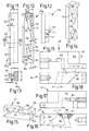
- Fig. 1:
- eine Schrägsicht auf ein Crimpwerkzeug in einer Anschlagpresse;
- Fig. 2:
- eine vergrößerte Schrägsicht auf einen Teil eines hülsenartigen Kontaktelementes;
- Fig. 3:
- den Querschnitt durch das Kontaktelement nach einem Verformvorgang;
- Fig. 4:
- die Frontansicht des Crimpwerkzeuges;
- Fig. 5:
- den gegenüber Fig. 4 verkleinerten Schnitt gemäß Linie M durch das Crimpwerkzeug;
- Fig. 6:
- einen Querschnitt durch das Crimpwerkzeug mit linkem und rechtem Druckstempel, dazwischenliegendem Crimpeinsatz und diesem geordneten seitlichen Druckbacken;
- Fig. 7:
- einen Querschnitt durch das Crimpwerkzeug in oberer Totpunktlage;
- Fig. 8:
- einen Querschnitt durch das Crimpwerkzeug in unterer Totpunktlage.
- Fig. 9:
- den linken Druckstempel des Crimpwerkzeuges;
- Fig. 10:
- den gegenüber Fig. 9 vergrößerten rechten Druckstempel in Frontansicht;
- Fig. 11:
- eine Seitenansicht zu Fig. 10;
- Fig. 12:
- einen Teil der anderen Seitenansicht zu Fig. 10;
- Fig. 13:
- den Schnitt durch Fig. 11 nach deren Linie XIII -XIII;
- Fig. 14:
- eine Schrägsicht auf den oberen Bereich des Druckstempels nach Fig. 10 bis 13;
- Fig. 15:
- eine Schrägsicht auf den in Fig. 6 bis 8 rechten unteren Druckbacken;
- Fig. 16:
- die vergrößerte Seitenansicht zu Fig. 15;
- Fig. 17:
- die Sicht unter den Druckbacken der Fig. 15,16;
- Fig. 18:
- die Seitenansicht des oberen linken Druckbackens der Fig. 6;
- Fig. 19:
- die Sicht unter den Druckbacken der Fig. 18.
- F1=
- vertikaler Pressenhub;
- F2=
- Übernahme von F1 als Längshub auf die Druckstempel 40,40a des Crimpwerkzeuges 20;
- F3=
- Übernahme des Längshubes F2 für den Querhub der Druckbacken 46,47;
- F4=
- Übernahme des Querhubes F3 als Diagonalhub für die Crimpstempel 28.
Claims (12)
- Crimpwerkzeug mit Crimpstempeln (28) zum Verbinden eines Drahtes mit einem Kontaktelement durch Verformen von Klemmteilen des Kontaktelements mittels der Crimpstempel in einer Crimpstellung, insbesondere zum auswechselbaren Anordnen in einer Anschlagpresse, wobei
zum Erzeugen mehrerer Verformungsbereiche (B) am Kontaktelement (26) eine deren Anordnung entsprechende Zahl von Crimpstempeln (28) um eine Aufnahmeöffnung (31) des Crimpwerkzeuges angeordnet ist, dadurch gekennzeichnet, daß jeder Crimpstempel durch einen Druckbacken (46, 47) zur Aufnahmeöffnung hin in die Crimpstellung überführbar ist, wobei die Druckbacken durch zu ihnen abgewinkelt angeordnete Druckstempel (40, 40a) bewegbar sind. - Vorrichtung nach Anspruch 1, gekennzeichnet durch beidseits einer Symmetriegeraden (M) angeordnete und zu ihr etwa parallele Druckstempel (40, 40a) des Crimpwerkzeuges (20) mit in einem Winkel (w) zur Symmetrieachse geneigten Flächen (50), die in die Bewegungsbahn (44) von Schrägflächen (58) der Druckbacken (46, 47) eingreifen.
- Vorrichtung nach Anspruch 1 oder 2, dadurch gekennzeichnet, daß zum Rückführen des Druckbackens (46, 47) dessen Schrägfläche/n (58) jeweils eine parallele Schrägfläche (60) gegenüberliegt, die einer zweiten geneigten Fläche (56) des Druckstempels (40, 40a) zugeordnet ist.
- Vorrichtung nach Anspruch 1 oder 3, dadurch gekennzeichnet, daß die zusammenwirkenden Rückholflächen (60 und 56) von Druckbacken (46, 48) und Druckstempel (40,40a) zur Symmetrieachse (M) geneigt sind.
- Vorrichtung nach einem der Ansprüche 1 bis 4, dadurch gekennzeichnet, daß der Druckbacken (46, 47) eine Keilfläche (66) aufweist, welche die Achse des zugeordneten Crimpstempels (28) quert und auf eine zu ihr parallele Stempelfläche (29) drückbar ist, wobei gegebenenfalls die die Achse (Q) des Crimpstempels (28) etwa rechtwinkelig zur Keilfläche (66) verläuft.
- Vorrichtung nach einem der Ansprüche 1 bis 3, dadurch gekennzeichnet, daß der Crimpstempel (28) gegen die Kraft eines Kraftspeichers in die Crimpstellung überführbar angeordnet ist.
- Vorrichtung nach wenigstens einem der Ansprüche 1 bis 6, dadurch gekennzeichnet, daß in einen den Druckbacken (46, 47) bildenden Werkstoffblock sowohl die Keilfläche (66) als auch eine gegenläufig geneigte Schrägnut (64) eingeformt sind, wobei letztere die Schrägflächen (58, 60) für die Crimp- und die Rückholbewegung anbietet.
- Vorrichtung nach wenigstens einem der Ansprüche 1 bis 7, dadurch gekennzeichnet, daß in die Schrägnut (64) des Druckbackens (46, 47) eine leistenartig vom Druckstempel (40) abragende Rippe (52) eingreift, welche die geneigten Flächen (50, 56) aufweist.
- Vorrichtung nach wenigstens einem der Ansprüche 1 bis 8, dadurch gekennzeichnet, daß der Druckstempel (40) mit einem heb- und senkbaren Drehkopf (22) verbunden und dieser an einen Pressenstempel (18) anschließbar ist, oder daß der Druckbacken (46, 47) gegen die Kraft eines Kraftspeichers (49) zum Crimpstempel (28) hin führbar ist.
- Vorrichtung nach wenigstens einem der Ansprüche 1 bis 9, dadurch gekennzeichnet, daß der Kraftspeicher (49) für den Druckbacken (46, 47) einen mit diesem verbundenen sowie eine festliegende Führung (36a) durchsetzenden Sicherungsbolzen (48) umfängt, und/oder, daß die Führung (36a) für den Sicherungsbolzen (48) eine Bohrung in einem Gehäuseteil (36) ist, wobei im Gehäuse (32) Gleitbahnen (44) für die Druckbacken (46, 47) verlaufen.
- Vorrichtung nach wenigstens einem der Ansprüche 1 bis 10, dadurch gekennzeichnet, daß quer zu den Gleitbahnen (44) Schubbahnen (38) für die Druckstempel (40) verlaufen, und/oder, daß zwischen den Schubbahnen (38) ein austauschbarer Crimpeinsatz (30) angeordnet und dieser mit Führungen (29) für die Crimpstempel (28) versehen ist, wobei gegebenenfalls die Führungen (29) radial zur Aufnahmeöffnung (31) im Crimpeinsatz (30) verlaufen, die sich bevorzugt zu den Führungen (29) hin verjüngt.
- Verfahren zum Verbinden eines Drahtes mit einem Kontaktelement durch Verformen von Klemmteilen des Kontaktelements (26) mittels Crimpstempeln (28) eines Crimpwerkzeugs in einer Anschlagpresse, wobei zum Erzeugen mehrerer Verformungsbereiche (B) am Kontaktelement eine deren Anordnung entsprechende Zahl von Crimpstempeln um eine Aufnahmeöffnung (31) des Crimpwerkzeugs angeordnet ist und die Kraft (F1) der Anschlagpresse (10) auf Druckstempel (40, 40a) des Crimpwerkzeuges (20) aufgeteilt, jede dieser Teilkräfte (F2) der Druckstempel in zumindest eine dazu abgewinkelt stehende Kraft (F3) eines Druckbackens umgesetzt und mit dieser der Crimpstempel (28) beaufschlagt wird (F4).
Applications Claiming Priority (4)
| Application Number | Priority Date | Filing Date | Title |
|---|---|---|---|
| DE4238018 | 1992-11-11 | ||
| DE4238018 | 1992-11-11 | ||
| DE4240498 | 1992-12-02 | ||
| DE4240498A DE4240498C2 (de) | 1992-11-11 | 1992-12-02 | Crimpwerkzeug zum Verbinden eines Drahtes mit einem Kontaktelement od.dgl. |
Publications (3)
| Publication Number | Publication Date |
|---|---|
| EP0597456A2 EP0597456A2 (de) | 1994-05-18 |
| EP0597456A3 EP0597456A3 (en) | 1996-11-13 |
| EP0597456B1 true EP0597456B1 (de) | 1999-05-26 |
Family
ID=25920351
Family Applications (1)
| Application Number | Title | Priority Date | Filing Date |
|---|---|---|---|
| EP93118210A Expired - Lifetime EP0597456B1 (de) | 1992-11-11 | 1993-11-10 | Vorrichtung und Verfahren zum Verbinden eines Drahtes mit einem Kontaktelement |
Country Status (7)
| Country | Link |
|---|---|
| US (1) | US5477608A (de) |
| EP (1) | EP0597456B1 (de) |
| AT (1) | ATE180600T1 (de) |
| DE (2) | DE4240498C2 (de) |
| DK (1) | DK0597456T3 (de) |
| ES (1) | ES2134236T3 (de) |
| GR (1) | GR3030962T3 (de) |
Families Citing this family (7)
| Publication number | Priority date | Publication date | Assignee | Title |
|---|---|---|---|---|
| DE19520928C2 (de) * | 1995-06-08 | 2003-05-15 | Bernhard Schaefer Werkzeug Und | Vorrichtung zum Verbinden eines Drahtes mit einem Kontaktelement |
| US6243947B1 (en) * | 1998-09-22 | 2001-06-12 | Sumitomo Wiring Systems, Ltd. | Method for processing an end of a shielded cable |
| WO2004109461A2 (en) * | 2003-06-04 | 2004-12-16 | Zusi Christopher J | Automated machine setup with modular tooling |
| DE102007063669B4 (de) * | 2007-01-29 | 2011-04-28 | Rennsteig Werkzeuge Gmbh | Crimpeinsatz für ein Crimpwerkzeug |
| WO2008150978A2 (en) * | 2007-06-01 | 2008-12-11 | The Siemon Company | Termination tool with longitudinal and transverse crimping capabilities |
| CH701681A1 (de) * | 2009-08-21 | 2011-02-28 | Schleuniger Holding Ag | Crimpwerkzeug und Verfahren zur Herstellung eines 4-Punkt-Crimps. |
| EP4716032A1 (de) | 2024-09-23 | 2026-03-25 | Schäfer Werkzeug- und Sondermaschinenbau GmbH | Vorrichtung zum verbinden eines kontaktelements mit einem leiter sowie verfahren |
Family Cites Families (18)
| Publication number | Priority date | Publication date | Assignee | Title |
|---|---|---|---|---|
| US2733458A (en) * | 1956-02-07 | Trurnit | ||
| CA573800A (en) * | 1959-04-07 | H. Appel Gerhard | Stroke adjustment means for forming machines | |
| GB723433A (en) * | 1953-03-04 | 1955-02-09 | George Henry Mercer | Improvements in methods of and machines for cold swaging and tagging metal stock |
| FR1145871A (fr) * | 1956-03-19 | 1957-10-30 | Machine destinée à la fabrication de barres profilées | |
| US2970500A (en) * | 1958-09-10 | 1961-02-07 | Appel Process Ltd | Forming machines |
| BE621603A (de) * | 1961-08-29 | |||
| US3626363A (en) * | 1969-07-29 | 1971-12-07 | Itt | Roll-formed contact and crimping device therefor |
| US3728889A (en) * | 1969-07-29 | 1973-04-24 | Itt | Crimping device |
| US4041766A (en) * | 1976-06-03 | 1977-08-16 | Gte Sylvania Incorporated | Swaging device for use within a die apparatus |
| US4178679A (en) * | 1978-03-13 | 1979-12-18 | Bernard Lichtenstein | Contact crimping machine |
| US4229963A (en) * | 1978-05-26 | 1980-10-28 | Savinov Evgeny A | Machine for noncutting metal shaping |
| DE3508397C2 (de) * | 1984-03-09 | 1986-06-12 | Zoller & Fröhlich GmbH & Co KG, 7988 Wangen | Maschine zum Aufquetschbestücken von Kabeladerenden mit Aderendhülsen o.dgl. Anschlußelementen |
| EP0166863B1 (de) * | 1984-03-09 | 1989-06-07 | ZOLLER & FRÖHLICH GMBH & CO. KG. | Maschine zum Aufquetschbestücken von Kabeladerenden mit Aderendhülsen od. dgl. Anschlusselementen |
| US4611484A (en) * | 1984-12-10 | 1986-09-16 | Amp Incorporated | Quick change mounting plate |
| US4711484A (en) * | 1987-02-19 | 1987-12-08 | Tuerk James R | Tarp cover system for flat bed vehicles |
| FR2615050B1 (fr) * | 1987-05-06 | 1992-09-11 | Telemecanique Electrique | Dispositif de pose et de sertissage d'embouts sur des conducteurs electriques |
| US4905490A (en) * | 1988-08-25 | 1990-03-06 | Wilson Glenn E | Lock combination decoder |
| DE4039051A1 (de) * | 1990-11-30 | 1992-06-17 | Bernhard Schaefer Werkzeug Und | Vorrichtung zum verbinden eines drahtes mit einem kontaktelement od. dgl. |
-
1992
- 1992-12-02 DE DE4240498A patent/DE4240498C2/de not_active Expired - Fee Related
-
1993
- 1993-11-09 US US08/150,445 patent/US5477608A/en not_active Expired - Fee Related
- 1993-11-10 ES ES93118210T patent/ES2134236T3/es not_active Expired - Lifetime
- 1993-11-10 DK DK93118210T patent/DK0597456T3/da active
- 1993-11-10 DE DE59309606T patent/DE59309606D1/de not_active Expired - Lifetime
- 1993-11-10 AT AT93118210T patent/ATE180600T1/de not_active IP Right Cessation
- 1993-11-10 EP EP93118210A patent/EP0597456B1/de not_active Expired - Lifetime
-
1999
- 1999-08-11 GR GR990402043T patent/GR3030962T3/el unknown
Also Published As
| Publication number | Publication date |
|---|---|
| DK0597456T3 (da) | 1999-12-06 |
| US5477608A (en) | 1995-12-26 |
| GR3030962T3 (en) | 1999-11-30 |
| DE4240498C2 (de) | 1996-05-02 |
| DE4240498A1 (de) | 1994-05-19 |
| ATE180600T1 (de) | 1999-06-15 |
| EP0597456A2 (de) | 1994-05-18 |
| EP0597456A3 (en) | 1996-11-13 |
| ES2134236T3 (es) | 1999-10-01 |
| DE59309606D1 (de) | 1999-07-01 |
Similar Documents
| Publication | Publication Date | Title |
|---|---|---|
| DE60215809T2 (de) | Längenverstellbares stanzwerkzeug | |
| EP0468335B1 (de) | Werkzeug zum Crimpen eines Verbinders mit einem Leiter einerseits und einer Isolierung andererseits | |
| DE19832884C1 (de) | Preßzange mit einem Zangenkopf und einem Positionierer | |
| EP2874804B1 (de) | Keiltrieb | |
| EP0542144B1 (de) | Vorrichtung zum Verbinden eines Drahtes mit einem Stecker, Kontaktelement od.dgl. | |
| EP2616197A1 (de) | Vorrichtung und verfahren zur herstellung von zumindest teilweise geschlossenen hohlprofilen mit drehbaren gesenkhälften und geringer taktzeit | |
| DE69704928T2 (de) | Verfahren und Maschine zum Schmieden eines Gegenstandes mit einem deformierten Endteil | |
| DE1602567B2 (de) | Sicherungseinrichtung am auswerfer einer stantmaschine | |
| DE19603281C2 (de) | Vorrichtung zur Herstellung von unter Preßsitz zusammengefügten elektrischen Kabelbäumen und zugehöriges Verfahren | |
| DE3876918T2 (de) | Werkzeugaufbau fuer drahteinschiebung. | |
| DE4240498C2 (de) | Crimpwerkzeug zum Verbinden eines Drahtes mit einem Kontaktelement od.dgl. | |
| DE2928707C2 (de) | Vorrichtung zum Herstellen von Gabelelementen | |
| DE3908867A1 (de) | Verfahren und vorrichtung zur herstellung von doppelanschlaegen an elektrischen verbindern | |
| DE3434470C2 (de) | Biegepresse | |
| EP0021166B1 (de) | Schmiedevorrichtung | |
| DE4039051C2 (de) | ||
| EP0226136B1 (de) | Vorrichtung zum spanlosen Bearbeiten von Bauteilen | |
| DE1903547A1 (de) | Verfahren zum Verjuengen der Enden von flexiblen Wellen | |
| EP0166863A1 (de) | Maschine zum Aufquetschbestücken von Kabeladerenden mit Aderendhülsen od. dgl. Anschlusselementen | |
| DE3304075C2 (de) | ||
| DE3815587A1 (de) | Vorrichtung zum aufsetzen und aufquetschen von anschlussstuecken auf elektrischen leitern | |
| EP0583223B1 (de) | Crimpwerkzeug für elektrische Stecker und Verwendung desselben | |
| DE2909214C2 (de) | Verfahren zum Herstellen eines Polschuhs für elektrische Maschinen | |
| DE19520928A1 (de) | Vorrichtung zum Verbinden eines Drahtes o. dgl. Rohlings mit einem Kontaktelement o. dgl. | |
| DE2344831B2 (de) | Verfahren zur Herstellung gekrümmter Fittings und Verwendung einer Einrichtung zur Durchführung des Verfahrens |
Legal Events
| Date | Code | Title | Description |
|---|---|---|---|
| PUAI | Public reference made under article 153(3) epc to a published international application that has entered the european phase |
Free format text: ORIGINAL CODE: 0009012 |
|
| AK | Designated contracting states |
Kind code of ref document: A2 Designated state(s): AT BE CH DE DK ES FR GB GR IE IT LI LU MC NL PT SE |
|
| PUAL | Search report despatched |
Free format text: ORIGINAL CODE: 0009013 |
|
| AK | Designated contracting states |
Kind code of ref document: A3 Designated state(s): AT BE CH DE DK ES FR GB GR IE IT LI LU MC NL PT SE |
|
| 17P | Request for examination filed |
Effective date: 19961122 |
|
| GRAG | Despatch of communication of intention to grant |
Free format text: ORIGINAL CODE: EPIDOS AGRA |
|
| 17Q | First examination report despatched |
Effective date: 19980929 |
|
| GRAG | Despatch of communication of intention to grant |
Free format text: ORIGINAL CODE: EPIDOS AGRA |
|
| GRAH | Despatch of communication of intention to grant a patent |
Free format text: ORIGINAL CODE: EPIDOS IGRA |
|
| GRAH | Despatch of communication of intention to grant a patent |
Free format text: ORIGINAL CODE: EPIDOS IGRA |
|
| GRAA | (expected) grant |
Free format text: ORIGINAL CODE: 0009210 |
|
| AK | Designated contracting states |
Kind code of ref document: B1 Designated state(s): AT BE CH DE DK ES FR GB GR IE IT LI LU MC NL PT SE |
|
| REF | Corresponds to: |
Ref document number: 180600 Country of ref document: AT Date of ref document: 19990615 Kind code of ref document: T |
|
| REG | Reference to a national code |
Ref country code: CH Ref legal event code: NV Representative=s name: HEPP, WENGER & RYFFEL AG Ref country code: CH Ref legal event code: EP |
|
| GBT | Gb: translation of ep patent filed (gb section 77(6)(a)/1977) |
Effective date: 19990607 |
|
| REF | Corresponds to: |
Ref document number: 59309606 Country of ref document: DE Date of ref document: 19990701 |
|
| ET | Fr: translation filed | ||
| REG | Reference to a national code |
Ref country code: IE Ref legal event code: FG4D Free format text: GERMAN |
|
| ITF | It: translation for a ep patent filed | ||
| REG | Reference to a national code |
Ref country code: ES Ref legal event code: FG2A Ref document number: 2134236 Country of ref document: ES Kind code of ref document: T3 |
|
| REG | Reference to a national code |
Ref country code: PT Ref legal event code: SC4A Free format text: AVAILABILITY OF NATIONAL TRANSLATION Effective date: 19990825 |
|
| REG | Reference to a national code |
Ref country code: DK Ref legal event code: T3 |
|
| PLBE | No opposition filed within time limit |
Free format text: ORIGINAL CODE: 0009261 |
|
| STAA | Information on the status of an ep patent application or granted ep patent |
Free format text: STATUS: NO OPPOSITION FILED WITHIN TIME LIMIT |
|
| 26N | No opposition filed | ||
| PGFP | Annual fee paid to national office [announced via postgrant information from national office to epo] |
Ref country code: GR Payment date: 20011018 Year of fee payment: 9 |
|
| PGFP | Annual fee paid to national office [announced via postgrant information from national office to epo] |
Ref country code: MC Payment date: 20011019 Year of fee payment: 9 |
|
| PGFP | Annual fee paid to national office [announced via postgrant information from national office to epo] |
Ref country code: GB Payment date: 20011022 Year of fee payment: 9 |
|
| PGFP | Annual fee paid to national office [announced via postgrant information from national office to epo] |
Ref country code: PT Payment date: 20011029 Year of fee payment: 9 |
|
| PGFP | Annual fee paid to national office [announced via postgrant information from national office to epo] |
Ref country code: ES Payment date: 20011114 Year of fee payment: 9 |
|
| PGFP | Annual fee paid to national office [announced via postgrant information from national office to epo] |
Ref country code: SE Payment date: 20011121 Year of fee payment: 9 |
|
| PGFP | Annual fee paid to national office [announced via postgrant information from national office to epo] |
Ref country code: FR Payment date: 20011122 Year of fee payment: 9 |
|
| PGFP | Annual fee paid to national office [announced via postgrant information from national office to epo] |
Ref country code: AT Payment date: 20011123 Year of fee payment: 9 |
|
| PGFP | Annual fee paid to national office [announced via postgrant information from national office to epo] |
Ref country code: DK Payment date: 20011126 Year of fee payment: 9 |
|
| PGFP | Annual fee paid to national office [announced via postgrant information from national office to epo] |
Ref country code: NL Payment date: 20011127 Year of fee payment: 9 Ref country code: BE Payment date: 20011127 Year of fee payment: 9 |
|
| PGFP | Annual fee paid to national office [announced via postgrant information from national office to epo] |
Ref country code: IE Payment date: 20011128 Year of fee payment: 9 |
|
| PGFP | Annual fee paid to national office [announced via postgrant information from national office to epo] |
Ref country code: LU Payment date: 20011129 Year of fee payment: 9 |
|
| REG | Reference to a national code |
Ref country code: GB Ref legal event code: IF02 |
|
| PG25 | Lapsed in a contracting state [announced via postgrant information from national office to epo] |
Ref country code: LU Free format text: LAPSE BECAUSE OF NON-PAYMENT OF DUE FEES Effective date: 20021110 Ref country code: GB Free format text: LAPSE BECAUSE OF NON-PAYMENT OF DUE FEES Effective date: 20021110 Ref country code: AT Free format text: LAPSE BECAUSE OF NON-PAYMENT OF DUE FEES Effective date: 20021110 |
|
| PG25 | Lapsed in a contracting state [announced via postgrant information from national office to epo] |
Ref country code: SE Free format text: LAPSE BECAUSE OF NON-PAYMENT OF DUE FEES Effective date: 20021111 Ref country code: IE Free format text: LAPSE BECAUSE OF NON-PAYMENT OF DUE FEES Effective date: 20021111 Ref country code: ES Free format text: LAPSE BECAUSE OF NON-PAYMENT OF DUE FEES Effective date: 20021111 |
|
| PG25 | Lapsed in a contracting state [announced via postgrant information from national office to epo] |
Ref country code: BE Free format text: LAPSE BECAUSE OF NON-PAYMENT OF DUE FEES Effective date: 20021130 |
|
| PG25 | Lapsed in a contracting state [announced via postgrant information from national office to epo] |
Ref country code: DK Free format text: LAPSE BECAUSE OF NON-PAYMENT OF DUE FEES Effective date: 20021231 |
|
| BERE | Be: lapsed |
Owner name: BERNHARD *SCHAFER WERKZEUG- U. SONDERMASCHINEN G.M Effective date: 20021130 |
|
| PG25 | Lapsed in a contracting state [announced via postgrant information from national office to epo] |
Ref country code: PT Free format text: LAPSE BECAUSE OF NON-PAYMENT OF DUE FEES Effective date: 20030531 |
|
| PG25 | Lapsed in a contracting state [announced via postgrant information from national office to epo] |
Ref country code: NL Free format text: LAPSE BECAUSE OF NON-PAYMENT OF DUE FEES Effective date: 20030601 Ref country code: MC Free format text: LAPSE BECAUSE OF NON-PAYMENT OF DUE FEES Effective date: 20030601 |
|
| PG25 | Lapsed in a contracting state [announced via postgrant information from national office to epo] |
Ref country code: GR Free format text: LAPSE BECAUSE OF NON-PAYMENT OF DUE FEES Effective date: 20030609 |
|
| EUG | Se: european patent has lapsed | ||
| GBPC | Gb: european patent ceased through non-payment of renewal fee | ||
| REG | Reference to a national code |
Ref country code: DK Ref legal event code: EBP |
|
| PG25 | Lapsed in a contracting state [announced via postgrant information from national office to epo] |
Ref country code: FR Free format text: LAPSE BECAUSE OF NON-PAYMENT OF DUE FEES Effective date: 20030731 |
|
| NLV4 | Nl: lapsed or anulled due to non-payment of the annual fee |
Effective date: 20030601 |
|
| REG | Reference to a national code |
Ref country code: PT Ref legal event code: MM4A Free format text: LAPSE DUE TO NON-PAYMENT OF FEES Effective date: 20030531 |
|
| REG | Reference to a national code |
Ref country code: IE Ref legal event code: MM4A |
|
| REG | Reference to a national code |
Ref country code: FR Ref legal event code: ST |
|
| REG | Reference to a national code |
Ref country code: ES Ref legal event code: FD2A Effective date: 20031213 |
|
| PG25 | Lapsed in a contracting state [announced via postgrant information from national office to epo] |
Ref country code: IT Free format text: LAPSE BECAUSE OF NON-PAYMENT OF DUE FEES Effective date: 20091110 |
|
| PGRI | Patent reinstated in contracting state [announced from national office to epo] |
Ref country code: IT Effective date: 20110616 |
|
| PGFP | Annual fee paid to national office [announced via postgrant information from national office to epo] |
Ref country code: DE Payment date: 20121114 Year of fee payment: 20 Ref country code: CH Payment date: 20121122 Year of fee payment: 20 |
|
| PGFP | Annual fee paid to national office [announced via postgrant information from national office to epo] |
Ref country code: IT Payment date: 20121116 Year of fee payment: 20 |
|
| REG | Reference to a national code |
Ref country code: DE Ref legal event code: R071 Ref document number: 59309606 Country of ref document: DE |
|
| REG | Reference to a national code |
Ref country code: CH Ref legal event code: PL |
|
| PG25 | Lapsed in a contracting state [announced via postgrant information from national office to epo] |
Ref country code: DE Free format text: LAPSE BECAUSE OF EXPIRATION OF PROTECTION Effective date: 20131112 |