EP0597245B1 - Atemschutzmaske mit Überdruck im Maskeninnenraum - Google Patents
Atemschutzmaske mit Überdruck im Maskeninnenraum Download PDFInfo
- Publication number
- EP0597245B1 EP0597245B1 EP93116117A EP93116117A EP0597245B1 EP 0597245 B1 EP0597245 B1 EP 0597245B1 EP 93116117 A EP93116117 A EP 93116117A EP 93116117 A EP93116117 A EP 93116117A EP 0597245 B1 EP0597245 B1 EP 0597245B1
- Authority
- EP
- European Patent Office
- Prior art keywords
- mask
- respiratory mask
- sensor
- protective respiratory
- area
- Prior art date
- Legal status (The legal status is an assumption and is not a legal conclusion. Google has not performed a legal analysis and makes no representation as to the accuracy of the status listed.)
- Expired - Lifetime
Links
- 230000000241 respiratory effect Effects 0.000 title claims description 14
- 239000012528 membrane Substances 0.000 claims description 15
- 238000007789 sealing Methods 0.000 claims description 6
- 230000003993 interaction Effects 0.000 claims description 5
- 210000004072 lung Anatomy 0.000 claims description 5
- 230000001681 protective effect Effects 0.000 claims 9
- 238000006073 displacement reaction Methods 0.000 claims 1
- 230000029058 respiratory gaseous exchange Effects 0.000 description 14
- 238000009423 ventilation Methods 0.000 description 5
- 230000009471 action Effects 0.000 description 2
- 230000008859 change Effects 0.000 description 2
- 230000008901 benefit Effects 0.000 description 1
- 230000002028 premature Effects 0.000 description 1
- 239000000523 sample Substances 0.000 description 1
- 230000007704 transition Effects 0.000 description 1
Images


Classifications
-
- A—HUMAN NECESSITIES
- A62—LIFE-SAVING; FIRE-FIGHTING
- A62B—DEVICES, APPARATUS OR METHODS FOR LIFE-SAVING
- A62B9/00—Component parts for respiratory or breathing apparatus
- A62B9/02—Valves
- A62B9/022—Breathing demand regulators
- A62B9/025—Breathing demand regulators with tilting opening action
-
- A—HUMAN NECESSITIES
- A62—LIFE-SAVING; FIRE-FIGHTING
- A62B—DEVICES, APPARATUS OR METHODS FOR LIFE-SAVING
- A62B18/00—Breathing masks or helmets, e.g. affording protection against chemical agents or for use at high altitudes or incorporating a pump or compressor for reducing the inhalation effort
- A62B18/08—Component parts for gas-masks or gas-helmets, e.g. windows, straps, speech transmitters, signal-devices
- A62B18/10—Valves
Definitions
- the invention relates to a breathing mask with positive pressure in the interior of the mask with a regulator on a connection piece of the breathing mask, a switching element on the regulator for generating the excess pressure and an actuating element acting on the switching element on the connecting piece for switching on the excess pressure.
- a regulator with overpressure generation in the mask interior which has the features mentioned in the preamble of claim 1, has become known from EP-B 91 843.
- the known regulator is provided with an attachment connector which can be plugged onto a connection piece of a respiratory mask.
- the regulator has a switching element for generating the excess pressure, which is connected to a sensor as an actuating element, which triggers the switchover to positive pressure ventilation.
- the positive pressure ventilation is switched on when the attachment piece with the sensor is inserted into the connecting piece.
- a disadvantage of the known regulators is that the switch to positive pressure ventilation is carried out regardless of whether the mask wearer has put on the respirator or not. If the regulator is plugged into the connector and the pressure switch is switched to overpressure mode, compressed gas continuously escapes through the metering valve of the regulator in the environment, which can lead to premature depletion of the breathing gas supply.
- a mouthpiece valve for breathing apparatus has become known from DE 28 42 247, which consists of a valve housing and a tube which can be displaced in the valve housing as the actuating element.
- the tube When the mouthpiece on the valve housing is put on, the tube is displaced in the direction of the mouthpiece, as a result of which the passage is released for the breathing gas.
- the known mouthpiece valve only serves to interrupt the supply of breathing gas when the mouthpiece is put down.
- a disadvantage of the known mouthpiece valve is that the tube must always be held against the full force of a return spring when the valve is in the open position.
- a lung-controlled diaphragm valve for respiratory masks has become known with a switching element in the form of a rocker arm pretensioned by spring elements, which can be brought from a stable switch-off position by pressure on a driver as an actuating element into the operating position for positive pressure ventilation.
- a disadvantage of the known diaphragm valve is that the switchover from the switch-off position to the operating position can be carried out regardless of whether the respirator mask is on or not; or it can happen that the respirator is removed and the mask wearer fails to bring the rocker arm into the switch-off position. In this case, breathing gas is lost unused.
- the present invention has for its object to improve a respirator with a regulator in such a way that the switch to overpressure operation is effective only with a respirator.
- the object is achieved in that the actuating element is guided out of the connecting piece to a border area between the respiratory protection mask and the face of a mask wearer in such a way that when the respirator mask is put on, it is brought into the switched-on position by interaction with a part of the face surface of the mask wearer.
- the advantage of the invention lies essentially in the fact that the regulator is switched to positive pressure ventilation only when a breathing mask is put on, in that a part of the face of the mask wearer is brought into engagement with an actuating element of the regulator. This prevents the regulator from being switched on accidentally or prematurely.
- the actuating element can, for example, be designed as a pin which is deflected when the respirator mask is put on, e.g. axially displaced, and actuated the switching element of the regulator.
- an electromechanical switch as the actuating element, which acts on the switching element generating the excess pressure via a control circuit.
- the part of the face surface which triggers the switching is the chin area of the mask wearer.
- the chin area is expedient because the breathing gas supply with the regulator is also in the mouth or chin area, and deformations of the sealing wheel in the chin area can be transferred particularly well to the actuating element in the form of a change of path when the respirator mask is put on.
- the switching element is expediently designed as a rocker arm mounted in a first joint and the actuating element as a rocker-like sensor mounted in a second joint, which are braced against one another by means of a coil spring acting on the rocker arm and a tension spring acting on the sensor.
- a change of path can be transmitted particularly well to the rocker-mounted sensor if it is attached below the chin.
- Appropriate positioning of the second joint on the sensor allows the actuating force transmitted to the mask carrier to be set in such a way that it is not perceived as disturbing.
- the sensor, the rocker arm and the springs are expediently attached to a bearing block on the connecting piece.
- the rocker arm in the area of the first joint has an offset area on which the sensor tip of the sensor rests when the regulator is switched off. If the sensor is now deflected through the chin of the mask wearer in the operating position, ie when the respirator mask is put on, the sensor tip slides out of the cranked area of the rocker arm, thereby the rocker arm is pivoted about the first joint under the action of the coil spring attached to it and gas metering is possible via the inlet valve of the regulator. When the respirator mask is removed, the tip of the probe slides back into the cranked area of the rocker arm due to the interaction of the tension and coil springs, causing the rocker arm to return to the stable switch-off position. The presence of an offset area on the rocker arm achieves a defined switchover point between the switch-off position and the operating position.
- the rocker arm and a valve control lever influencing the inlet valve of the regulator are articulated in one eye of a driver actuating the diaphragm of the regulator.
- Figure 1 shows a partial view of a respirator (1) in longitudinal section with a mask body (2) and with a sealing edge (3) attached to the mask body (2), which lies against the face of a mask wearer (4) and has a depression (6) in a chin area (5).
- a valve housing (7) is inserted into the mask body (2), which encloses a regulator (8) with a membrane (9), a driver (10), a rocker arm (11) and an inlet valve (12).
- the valve housing (7) is designed as an inlet valve housing (13), with a compressed gas connection (14) through which the breathing gas enters a primary pressure chamber (15) in the inlet valve housing (13).
- the inlet valve (12) consists of a valve body (16), which rests on a valve seat (17) and a compensation piston (18) connected to the valve body (16) for back pressure compensation, which is actuated by a valve control lever (34).
- the valve control lever (34) is rotatably mounted in a joint (35) within the inlet valve housing (13) and has an eccentric disk (37) in the region of the joint (35), through which the compensation piston (18 ) is operated.
- the valve control lever (34) and the rocker arm (11) are articulated together in the driver (10).
- the rocker arm (11) is rotatably mounted in a first joint (19) on a bearing block (36) and is preloaded by means of a helical spring (20).
- the coil spring (20) is mounted on the rocker arm (11) in such a way that the rocker arm (11) can be switched from an operating position in which the inlet valve (12) can be actuated by the membrane (9) to a stable switch-off position , in which the inlet valve (12) is closed.
- the rocker arm (11) has Area of the first joint (19) a cranking area (21).
- a sensor (23) which rests on the one hand in the chin area (5) of the sealing edge (3) and on the other hand acts on the rocker arm (11), is also rotatably mounted on the bearing block (36) in a second joint (22) and by means of a tension spring (24) biased towards the rocker arm (11).
- An inner mask (25) is buttoned into the valve housing (7), which rests on the face of the mask wearer (4) and covers the inside of the recess (6) in the area of the sealing edge (3).
- the inner mask (25) surrounds a mask interior (26) as a secondary pressure space, which is delimited in the area of the valve housing (7) by the membrane (9).
- the membrane (9) of the regulator (8) is fastened in a membrane housing (27) with a membrane cover (28), which are also parts of the valve housing (7).
- the membrane (9) is pressed against a membrane valve seat (30) on the membrane housing by means of a membrane spring (29).
- the membrane cover (28) is provided with exhalation openings (31).
- the diaphragm housing (27) is followed by a connecting piece (32), which is also part of the valve housing (7) and contains the bearing block (36).
- Figure 1 shows the rocker arm (11) and the membrane (9) of the regulator (8) at the transition from the switch-off position (solid line) in the operating position with a respirator mask (dashed line).
- Inlet valve (12) can be opened via the diaphragm (9) in that a pressure drop is generated in the mask interior (26) by the inhalation of the mask carrier (4), the diaphragm (9) is deflected and the valve control lever (34) is moved via the driver (10). is rotated in the joint (35) such that the valve body (16) lifts off the valve seat (17) by rotating the eccentric disk (37), which is connected to the valve control lever (34), and breathing gas from the primary pressure chamber (15) into the mask interior (26) flows.
- the valve control lever (34) is also drawn in dashed lines in the operating position. With increasing pressure in the mask interior (26), the inlet valve (12) closes again. During exhalation, a pressure increase occurs in the interior of the mask (26), as a result of which the diaphragm (9) is pressed against the diaphragm spring (29) in the open position and the exhaled gas reaches the surroundings via the diaphragm valve seat (30) and the exhalation openings (31).
- the sensor (23) rotates around the second joint (22) and moves in the direction of the arrow (33), causing the rocker arm (11) to jump into the stable switch-off position in which the inlet valve (12) is blocked and the inflow of breathing gas into the mask interior (26) is interrupted (solid line of rocker arm (11), membrane (9) and valve control lever (34)).
- FIGS. 2 and 3 The interaction of the sensor (23) with the rocker arm (11) is illustrated in FIGS. 2 and 3. The same components are identified by the same reference numerals in FIG. 1.
- Figure 2 shows the bearing block (36) with the sensor (23) and the rocker arm (11), which around the joints (22, 19) are pivotable and braced against one another by springs (20, 24) fastened to the bearing block (36).
- the coil spring (20) is attached to a first attachment point (39) of the rocker arm (11) and the tension spring (24) is attached to a second attachment point (41) of the sensor.
- the sensor (23) is in the switch-off position and the sensor tip (38) lies on the offset area (21) of the rocker arm (11).
- the offset area (21) extends from the first joint (19) up to approximately 70% of the total distance between the first joint (19) and the first attachment point (39).
- the offset area (21) serves to have a defined switchover point between the switch-off position and the operating position.
- Figure 3 shows the sensor (23) and the rocker arm (11) in the operating position, in which the sensor (23) was deflected by the chin of the mask wearer when the respirator mask was put on.
- the sensor tip (38) slides out of the offset area (21) along the rocker arm (11), whereby this is pivoted upwards by the coil spring (20) and gas metering via the inlet valve (12), Fig. 1, is possible.
- the tension spring (24) is dimensioned such that it returns the sensor (23) to the switch-off position when the respirator mask (1) is removed, contrary to the action of the coil spring (20).
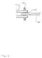
- FIG 4 illustrates the articulated connection of the rocker arm (11) and the valve control lever (34) with the driver (10).
- the driver (10) has on its rod-shaped shaft an eye (40) through which both the rocker arm (11) and the valve star lever (34) are guided and follow the movement of the membrane (9), Figure 1.
Landscapes
- Health & Medical Sciences (AREA)
- Pulmonology (AREA)
- General Health & Medical Sciences (AREA)
- Business, Economics & Management (AREA)
- Emergency Management (AREA)
- Respiratory Apparatuses And Protective Means (AREA)
Description
- Die Erfindung betrifft eine Atemschutzmaske mit Überdruck im Maskeninnenraum mit einem Lungenautomaten an einem Anschlußstutzen der Atemschutzmaske, einem Schaltglied am Lungenautomaten zur Erzeugung des Überdrucks und einem auf das Schaltglied wirkenden Betätigungselement am Anschlußstutzen zur Einschaltung des Überdrucks.
- Ein Lungenautomat mit Überdruckerzeugung im Maskeninnenraum, der die im Oberbegriff des Anspruchs 1 genannten Merkmale aufweist, ist aus der EP-B 91 843 bekanntgeworden. Der bekannte Lungenautomat ist mit einem Ansatzverbindungsstück versehen, welches auf einen Anschlußstutzen einer Atemschutzmaske aufsteckbar ist. Der Lungenautomat besitzt ein Schaltglied zur Erzeugung des Überdrucks, das mit einem Fühler als Betätigungselement verbunden ist, welcher die Umschaltung auf Überdruckbeatmung auslöst. Die Überdruckbeatmung wird eingeschaltet, wenn das Ansatzstück mit dem Fühler in den Anschlußstutzen eingesteckt wird.
- Nachteilig bei dem bekannten Lungenautomaten ist, daß die Umschaltung auf Überdruckbeatmung unabhängig davon vorgenommen wird, ob der Maskenträger die Atemschutzmaske angelegt hat oder nicht. Ist der Lungenautomat bei nicht angelegter Atemschutzmaske in den Anschlußstutzen eingesteckt und auf Überdruckbetrieb geschaltet, entweicht kontinuierlich Druckgas über das Dosierventil des Lungenautomaten in die Umgebung, was zu einem vorzeitigen Aufbrauch des Atemgasvorrates führen kann.
- Aus der DE 28 42 247 ist ein Mundstückventil für Atemschutzgeräte bekanntgeworden, welches aus einem Ventilgehäuse und einem im Ventilgehäuse verschiebbaren Tubus als Betätigungselement besteht. Beim Anlegen des am Ventilgehäuse befindlichen Mundstücks wird der Tubus in Richtung des Mundstückes verschoben, wodurch der Durchgang für das Atemgas freigegeben ist. Das bekannte Mundstückventil dient nur zum Unterbrechen der Atemgaszufuhr bei abgelegtem Mundstück. Nachteilig bei dem bekannten Mundstückventil ist, daß der Tubus bei der Öffnungsstellung des Ventils immer gegen die volle Kraft einer Rückstellfeder gehalten werden muß.
- Aus der DE-C 35 39 668 ist ein lungengesteuertes Membranventil für Atemschutzmasken bekanntgeworden mit einem Schaltglied in Form eines durch Federelemente vorgespannten Kipphebels, welcher aus einer stabilen Abschaltlage durch Druck auf einen Mitnehmer als Betätigungselement in die Betriebsstellung für die Überdruckbeatmung bringbar ist.
- Nachteilig bei dem bekannten Membranventil ist, daß die Umschaltung von der Abschaltlage auf die Betriebsstellung unabhängig davon ausgeführt werden kann, ob die Atemschutzmaske angelegt ist oder nicht; bzw. es kann der Fall eintreten, daß die Atemschutzmaske abgelegt wird und der Maskenträger es unterläßt, den Kipphebel in die Abschaltlage zu bringen. In diesem Fall geht Atemgas ungenutzt verloren.
- Der vorliegenden Erfindung liegt die Aufgabe zugrunde, eine Atemschutzmaske mit einem Lungenautomaten derart zu verbessern, daß die Umschaltung auf Überdruckbetrieb nur bei angelegter Atemschutzmaske wirksam ist.
- Die Lösung der Aufgabe erfolgt dadurch, daß das Betätigungselement derart aus dem Anschlußstutzen heraus an einen Grenzbereich zwischen Atemschutzmaske und Gesicht eines Masketrägers geführt ist, daß es beim Anlegen der Atemschutzmaske durch Wechselwirkung mit einem Gesichtsflächenteil des Maskenträgers in Einschaltstellung gebracht ist.
- Der Vorteil der Erfindung liegt im wesentlichen darin, daß der Lungenautomat erst bei angelegter Atemschutzmaske auf die Überdruckbeatmung geschaltet wird, indem ein Gesichtsflächenteil des Maskenträgers mit einem Betätigungselement des Lungenautomaten in Eingriff gebracht wird. Ein versehentliches oder vorzeitiges Einschalten des Lungenautomaten wird dadurch verhindert. Das Betätigungselement kann beispielsweise als ein Stift ausgeführt sein, der beim Anlegen der Atemschutzmaske ausgelenkt wird, z.B. axial verschoben wird, und dabei das Schaltglied des Lungenautomaten betätigt. Es ist aber auch möglich, als Betätigungselement einen elektromechanischen Schalter vorzusehen, welcher über eine Steuerungsschaltung auf das den Überdruck erzeugende Schaltglied einwirkt.
- Vorteilhafte Ausgestaltungen der Erfindung sind in den Unteransprüchen angegeben.
- Es ist vorteilhaft, als Grenzbereich zwischen Atemschutzmaske und Gesicht des Maskenträgers eine Mulde des Dichtrades der Atemschutzmaske zu nehmen, wobei das die Umschaltung auslösende Gesichtsflächenteil der Kinnbereich des Maskenträgers ist. Der Kinnbereich ist deswegen zweckmäßig, da sich die Atemgaszuführung mit dem Lungenautomaten ebenfalls im Mund- bzw. Kinnbereich befindet, und sich Verformungen des Dichtrades im Kinnbereich beim Aufsetzen der Atemschutzmaske besonders gut auf das Betätigungselement in Form einer Wegänderung übertragen lassen.
- In zweckmäßiger Weise ist das Schaltglied als ein in einem ersten Gelenk gelagerter Kipphebel und das Betätigungselement als ein wippenförmig in einem zweiten Gelenk gelagerter Fühler ausgeführt, welche mittels einer am Kipphebel angreifenden Schraubenfeder und einer am Fühler angreifenden Zugfeder gegeneinander verspannt sind. Auf den wippenförmig gelagerten Fühler läßt sich eine Wegänderung besonders gut übertragen, wenn dieser unterhalb des Kinns angebracht ist. Durch eine entsprechende Positionierung des zweiten Gelenks am Fühler läßt sich die auf den Maskenträger übertragene Betätigungskraft so einstellen, daß sie nicht als störend empfunden wird. Der Fühler, der Kipphebel und die Federn sind zweckmäßigerweise an einem Lagerbock am Anschlußstutzen befestigt.
- In zweckmäßiger Weise besitzt der Kipphebel im Bereich des ersten Gelenks einen Kröpfungsbereich, auf welchem in der Abschaltlage des Lungenautomaten die Fühlerspitze des Fühlers aufliegt. Wird nun in der Betriebsstellung, d.h. beim Anlegen der Atemschutzmaske, der Fühler durch das Kinn des Maskenträgers ausgelenkt, gleitet die Fühlerspitze aus dem Kröpfungsbereich des Kipphebels heraus, wodurch der Kipphebel unter der Wirkung der an ihm befestigten Schraubenfeder um das erste Gelenk geschwenkt wird und eine Gasdosierung über das Einlaßventil des Lungenautomaten möglich ist. Beim Ablegen der Atemschutzmaske gleitet die Fühlerspitze durch das Zusammenspiel der Zug- und der Schraubenfeder in den Kröpfungsbereich des Kipphebels zurück, wodurch dieser die stabile Abschaltlage wieder einnimmt. Durch das Vorhandensein eines Kröpfungsbereichs am Kipphebel wird ein definierter Umschaltpunkt zwischen Abschaltlage und Betriebsstellung erreicht.
- In zweckmäßiger Weise sind der Kipphebel und ein das Einlaßventil des Lungenautomaten beeinflussender Ventilsteuerhebel gelenkig in einem Auge eines die Membran des Lungenautomaten betätigenden Mitnehmers verbunden.
- Ein Ausführungsbeispiel der Erfindung ist in der Zeichnung dargestellt und im folgenden näher erläutert.
- Es zeigen:
- Figur 1
- eine Atemschutzmaske mit einem Lungenautomaten im Schnitt,
- Figur 2
- eine schematische Darstellung der Überdruckeinschaltvorrichtung,
- Figur 3
- die Überdruckschaltvorrichtung nach der Figur 2 in Betriebsstellung,
- Figur 4
- eine Teilansicht A nach der Figur 1 mit Blick auf den Mitnehmer.
- Figur 1 zeigt eine Teilansicht einer Atemschutzmaske (1) im Längsschnitt mit einem Maskenkörper (2) und mit einem an dem Maskenkörper (2) befestigten Dichtrand (3), welcher am Gesicht eines Maskenträgers (4) anliegt und in einem Kinnbereich (5) eine Mulde (6) besitzt. In den Maskenkörper (2) ist ein Ventilgehäuse (7) eingesetzt, welches einen Lungenautomaten (8) mit einer Membran (9), einem Mitnehmer (10), einem Kipphebel (11) und einem Einlaßventil (12) umschließt. Im Bereich des Einlaßventils (12) ist das Ventilgehäuse (7) als ein Einlaßventilgehäuse (13) ausgebildet, mit einem Druckgasanschluß (14), durch welchen das Atemgas in einen Primärdruckraum (15) im Einlaßventilgehäuse (13) gelangt. Das Einlaßventil (12) besteht aus einem Ventilkörper (16), welcher auf einem Ventilsitz aufliegt (17) und einem mit dem Ventilkörper (16) verbundenen Kompensationskolben (18) zur Vordruckkompensation, welcher durch einen Ventilsteuerhebel (34) betätigt wird. Der Ventilsteuerhebel (34) ist in einem Gelenk (35) innerhalb des Einlaßventilgehäuses (13) drehbar gelagert, und besitzt im Bereich des Gelenks (35) eine Exzenterscheibe (37), durch welche bei der Schwenkbewegung des Ventilsteuerhebels (34) der Kompensationskolben (18) betätigt wird. Der Ventilsteuerhebel (34) und der Kipphebel (11) sind in dem Mitnehmer (10) gelenkig zusammen geführt. Der Kipphebel (11) ist in einem ersten Gelenk (19), an einem Lagerbock (36) drehbar gelagert und mittels einer Schraubenfeder (20) vorgespannt. Die Schraubenfeder (20) ist an dem Kipphebel (11), in der Weise montiert, daß der Kipphebel (11) von einer Betriebsstellung, in der das Einlaßventil (12) durch die Membran (9) betätigbar ist, in eine stabile Abschaltlage schaltbar ist, in welcher das Einlaßventil (12) geschlossen ist. Zur Realisierung der Umschaltfunktion besitzt der Kipphebel (11) im Bereich des ersten Gelenks (19) einen Kröpfungsbereich (21). Ein Fühler (23), welcher einerseits im Kinnbereich (5) des Dichtrandes (3) anliegt und andererseits auf den Kipphebel (11) einwirkt, ist ebenfalls an dem Lagerbock (36) in einem zweiten Gelenk (22) drehbar gelagert und mittels einer Zugfeder (24) gegenüber dem Kipphebel (11) vorgespannt. In das Ventilgehäuse (7) ist eine Innenmaske (25) eingeknöpft, welche an dem Gesicht des Maskenträgers (4) anliegt und im Bereich des Dichtrandes (3) die Innenseite der Mulde (6) überdeckt. Die Innenmaske (25) umschließt als Sekundärdruckraum einen Maskeninnenraum (26), der im Bereich des Ventilgehäuses (7) durch die Membran (9) begrenzt wird. Bei aufgesetzter Atemschutzmaske (1) stützt sich der Fühler (23) über die Innenmaske (25) und die Mulde (6) an der Unterseite des Kinns des Maskenträgers (4) ab.
- Die Membran (9) des Lungenautomaten (8) ist in einem Membrangehäuse (27) mit einem Membrandeckel (28) befestigt, welche ebenfalls Teile des Ventilgehäuses (7) sind. Die Membran (9) wird mittels einer Membranfeder (29) gegen einen Membranventilsitz (30) am Membrangehäuse gedrückt. Der Membrandeckel (28) ist mit Ausatemöffnungen (31) versehen.
In Richtung der Innenmaske (25) schließt sich an das Membrangehäuse (27) ein Anschlußstutzen (32) an, welcher ebenfalls Teil des Ventilgehäuses (7) ist und den Lagerbock (36) enthält. - Figur 1 zeigt den Kipphebel (11) und die Membran (9) des Lungenautomaten (8) beim Übergang von der Abschaltlage (ausgezogene Linie) in der Betriebsstellung bei angelegter Atemschutzmaske (gestrichelte Linie). In der Betriebsstellung ist das Einlaßventil (12) über die Membran (9) dadurch öffenbar, daß durch die Einatmung des Maskenträgers (4) im Maskeninnenraum (26) eine Druckabsenkung erzeugt wird , die Membran (9) ausgelenkt und über den Mitnehmer (10) der Ventilsteuerhebel (34) derart in dem Gelenk (35) gedreht wird, daß der Ventilkörper (16) durch Drehung der Exzenterscheibe (37), welche mit dem Ventilsteuerhebel (34) verbunden ist, vom Ventilsitz (17) abhebt und Atemgas vom Primärdruckraum (15) in den Maskeninnenraum (26) strömt. Der Ventilsteuerhebel (34) ist in der Betriebsstellung ebenfalls gestrichelt gezeichnet. Mit steigendem Druck im Maskeninnenraum (26) schließt das Einlaßventil (12) wieder. Bei der Ausatmung entsteht im Maskeninnenraum (26) ein Druckanstieg, wodurch die Membran (9) gegen die Membranfeder (29) in Öffnungsstellung gedrückt wird und das Ausatemgas über den Membranventilsitz (30) und die Ausatemöffnungen (31) in die Umgebung gelangt.
- Wird die Atemschutzmaske (1) abgelegt, vollführt der Fühler (23) eine Drehung um das zweite Gelenk (22) und bewegt sich in Richtung des Pfeils (33), wodurch der Kipphebel (11) in die stabile Abschaltlage überspringt, in der das Einlaßventil (12) abgesperrt und der Zustrom an Atemgas in den Maskeninnenraum (26) unterbrochen ist (ausgezogene Linie von Kipphebel (11), Membran (9) und Ventilsteuerhebel (34)).
- In den Figuren 2 und 3 ist das Zusammenwirken des Fühlers (23) mit dem Kipphebel (11) veranschaulicht. Gleiche Komponenten sind mit gleichen Bezugsziffern der Figur 1 bezeichnet.
- Figur 2 zeigt den Lagerbock (36) mit dem Fühler (23) und dem Kipphebel (11), welche um die Gelenke (22, 19) schwenkbar und durch am Lagerbock (36) befestigte Federn (20, 24) gegeneinander verspannt sind. Die Schraubenfeder (20) ist an einem ersten Befestigungspunkt (39) des Kipphebels (11) und die Zugfeder (24) an einem zweiten Befestigungspunkt (41) des Fühlers befestigt. Bei der in der Figur 2 gezeigten Position befindet sich der Fühler (23) in der Abschaltlage und die Fühlerspitze (38) liegt auf dem Kröpfungsbereich (21) des Kipphebels (11) auf. Der Kröpfungsbereich (21) erstreckt sich, vom ersten Gelenk (19) ausgehend, bis etwa 70% der Gesamtstrecke zwischen dem erstem Gelenk (19) und dem erstem Befestigungspunkt (39). Der Kröpfungsbereich (21) dient dazu, einen definierten Umschaltpunkt zwischen Abschaltlage und Betriebsstellung zu haben.
- Figur 3 zeigt den Fühler (23) und den Kipphebel (11) in der Betriebsstellung, bei welcher der Fühler (23), beim Anlegen der Atemschutzmaske durch das Kinn des Maskenträgers ausgelenkt wurde. Hierbei gleitet die Fühlerspitze (38) aus dem Kröpfungsbereich (21) heraus längs des Kipphebels (11), wodurch dieser durch die Schraubenfeder (20) nach oben geschwenkt wird und eine Gasdosierung über das Einlaßventil (12), Fig. 1, möglich ist. Wird die Atemschutzmaske wieder abgelegt, ist der Fühler (23) freigegeben und durch das Zusammenspiel der Federn (20, 24), gleitet die Fühlerspitze (38) in Richtung des Kröpfungsbereichs (21), wodurch der Kipphebel (11) die stabile Abschaltlage wieder einnimmt. Genauer gesagt ist die Zugfeder (24) so dimensioniert, daß sie den Fühler (23) bei abgelegter Atemschutzmaske (1), entgegen der Wirkung der Schraubenfeder (20), in die Abschaltlage zurückführt.
- Figur 4 veranschaulicht die gelenkige Verbindung des Kipphebels (11) und des Ventilsteuerhebels (34) mit dem Mitnehmer (10). Der Mitnehmer (10) besitzt an seinem stabförmigen Schaft ein Auge (40) durch welches sowohl der Kipphebel (11) als auch der Ventilsternerhebel (34) geführt sind und der Bewegung der Membran (9), Figur 1, folgen.
Claims (5)
- Atemschutzmaske (1) mit Überdruck im Maskeninnenraum (26) mit einem Lungenautomaten (8) an einem Anschlußstutzen (32) der Atemschutzmaske, einem Schaltglied (11) am Lungenautomaten zur Erzeugung des Überdrucks und einem auf das Schaltglied wirkenden Betätigungselement (23) am Anschlußstutzen zur Einschaltung des Überdrucks, dadurch gekennzeichnet, daß das Betätigungselement (23) in Form eines wegaufnehmenden Fühlers derart aus dem Anschlußstutzen (32) heraus an einen Grenzbereich (6) zwischen Atemschutzmaske (1) und Gesicht eines Maskenträgers (4) geführt ist, daß es beim Anlegen der Atemschutzmaske durch Wechselwirkung mit einem Gesichtsflächenteil (5) des Maskenträgers (4) in Einschaltstellung gebracht ist.
- Atemschutzmaske nach Anspruch 1, dadurch gekennzeichnet, daß der Grenzbereich eine Mulde (6) eines Dichtrandes (3) der Atemschutzmaske (1) ist und das Gesichtsflächenteil der Kinnbereich (5) des Maskenträgers (4) ist.
- Atemschutzmaske nach Anspruch 1 oder 2, dadurch gekennzeichnet, daß das Betätigungselement als ein wippenförmig in einem zweiten Gelenk (22) gelagerter Fühler (23) und das Schaltglied als ein in einem ersten Gelenk (19) gelagerter Kipphebel (11) ausgeführt sind, welche mittels einer am Fühler (23) angreifenden Zugfeder (24) und einer am Kipphebel (11) angreifenden Schraubenfeder (20) gegeneinander verspannt sind.
- Atemschutzmaske nach Anspruch 3, dadurch gekennzeichnet, daß der Kipphebel (11) im Bereich des ersten Gelenks (19) einen Kröpfungsbereich (21) besitzt, auf welchem in der Abschaltlage des Lungenautomaten (8) eine Fühlerspitze (38) des Fühlers (23) aufliegt.
- Atemschutzmaske nach Anspruch 3 oder 4, dadurch gekennzeichnet, daß der Kipphebel (11) und ein ein Einlaßventil (12) beeinflussender Ventilsteuerhebel (34) gelenkig in einem Auge (40) eines die Membran (9) des Lungenautomaten (8) betätigenden Mitnehmers (10) verbunden sind.
Applications Claiming Priority (2)
| Application Number | Priority Date | Filing Date | Title |
|---|---|---|---|
| DE4237294A DE4237294C1 (de) | 1992-11-05 | 1992-11-05 | Atemschutzmaske mit Überdruck im Maskeninnenraum |
| DE4237294 | 1992-11-05 |
Publications (2)
| Publication Number | Publication Date |
|---|---|
| EP0597245A1 EP0597245A1 (de) | 1994-05-18 |
| EP0597245B1 true EP0597245B1 (de) | 1996-07-03 |
Family
ID=6472118
Family Applications (1)
| Application Number | Title | Priority Date | Filing Date |
|---|---|---|---|
| EP93116117A Expired - Lifetime EP0597245B1 (de) | 1992-11-05 | 1993-10-06 | Atemschutzmaske mit Überdruck im Maskeninnenraum |
Country Status (3)
| Country | Link |
|---|---|
| US (1) | US5499624A (de) |
| EP (1) | EP0597245B1 (de) |
| DE (2) | DE4237294C1 (de) |
Families Citing this family (16)
| Publication number | Priority date | Publication date | Assignee | Title |
|---|---|---|---|---|
| DE4418788A1 (de) * | 1994-05-24 | 1995-11-30 | Interspiro Gmbh | Atemanschluß mit Lungenautomat |
| FR2740691B1 (fr) * | 1995-11-02 | 1998-01-09 | France Etat | Cartouche modulatrice de contre pression pour masque respiratoire |
| GB9619459D0 (en) * | 1996-09-18 | 1996-10-30 | Jackson Peter J | Breathing apparatus |
| FR2781381B1 (fr) * | 1998-07-24 | 2000-09-29 | Intertechnique Sa | Regulateur a la demande pour systeme respiratoire |
| US6371110B1 (en) | 1999-03-25 | 2002-04-16 | Enviromental Tectonics Corporation | Automatic release apparatus and methods for respirator devices |
| EP1274486A2 (de) | 2000-04-17 | 2003-01-15 | Scott Technologies, Inc. | Atemmaske und wartungsmodul |
| US7007690B1 (en) * | 2000-08-31 | 2006-03-07 | The United States Of America As Represented By The Secretary Of The Army | Advanced chemical/biological crew mask |
| DE10159219B4 (de) * | 2001-11-27 | 2005-09-29 | Msa Auer Gmbh | Atemschutzmaske für einen Preßluftatmer |
| DE102004052173B3 (de) * | 2004-10-27 | 2006-01-12 | Dräger Safety AG & Co. KGaA | Atemschutzmaske für Normaldruck- und Überdruckbetrieb |
| US7814903B2 (en) * | 2006-06-05 | 2010-10-19 | Gentex Corporation | Integrated control circuit for an oxygen mask |
| US8955516B2 (en) * | 2009-04-08 | 2015-02-17 | Scott Technologies, Inc. | Face seals for respirators and method of manufacturing respirators |
| EP2361656B1 (de) * | 2010-02-26 | 2016-06-08 | Dräger Safety AG & Co. KGaA | Atemschutzmaske |
| AU2016315661B2 (en) | 2015-09-01 | 2019-08-15 | 3M Innovative Properties Company | Providing safety related contextual information in a personal protective equipment system |
| EP4364818B1 (de) | 2016-03-28 | 2025-10-29 | 3M Innovative Properties Company | Atemschutzmaske |
| JP2019529018A (ja) * | 2016-09-12 | 2019-10-17 | カナダ プロスパー アパレル リミテッド | 空気をろ過するためのフェイスマスクおよび空気監視システム |
| US20210368877A1 (en) * | 2020-06-02 | 2021-12-02 | Virender K. Sharma | Personal Air Management Methods and Systems for Reducing or Blocking Exposure to Airborne Pathogens |
Family Cites Families (14)
| Publication number | Priority date | Publication date | Assignee | Title |
|---|---|---|---|---|
| US3073301A (en) * | 1958-07-16 | 1963-01-15 | Air Reduction | Aviation quick release valve |
| US3019788A (en) * | 1959-02-10 | 1962-02-06 | Hughes William | Oxygen dispenser |
| US3186407A (en) * | 1960-03-23 | 1965-06-01 | Kathryn J Morrison | Gas storing and dispensing device |
| FR1378213A (fr) * | 1963-09-13 | 1964-11-13 | Goupil S A Lab | Dispositif inhalateur d'air suroxygéné |
| GB1317172A (en) * | 1970-05-21 | 1973-05-16 | Ml Aviation Co Ltd | Respirators |
| US3629868A (en) * | 1970-07-21 | 1971-12-28 | Trison Corp | Adapter assembly for a welding helmet or the like |
| US4119097A (en) * | 1977-02-03 | 1978-10-10 | Applied Research Commodities Industries, Inc. | Emergency oxygen supply |
| DE2842247C3 (de) * | 1978-09-26 | 1981-03-19 | Auergesellschaft Gmbh, 1000 Berlin | Mundstückventil für Atemschutzgeräte |
| FR2511252A1 (fr) * | 1982-04-02 | 1983-02-18 | Fenzy Sa | Embout pour appareil respiratoire pour le raccordement du masque a une bouteille de gaz respiratoire |
| FR2582524B1 (fr) * | 1985-05-31 | 1989-01-13 | Air Liquide | Cagoule de protection contre les fumees et l'hypoxie |
| GB8524181D0 (en) * | 1985-10-01 | 1985-11-06 | Stewart J S S | Breathing equipment |
| DE3539668A1 (de) * | 1985-11-08 | 1987-05-21 | Draegerwerk Ag | Lungengesteuertes membranventil fuer atemschutzmasken |
| DE3724336A1 (de) * | 1987-07-23 | 1989-02-02 | Draegerwerk Ag | Schutzmaske mit eingebautem sensor zur ueberwachung von lebensfunktionen |
| GB2215615B (en) * | 1988-03-21 | 1991-12-18 | Sabre Safety Ltd | Breathing apparatus |
-
1992
- 1992-11-05 DE DE4237294A patent/DE4237294C1/de not_active Expired - Fee Related
-
1993
- 1993-10-06 DE DE59303132T patent/DE59303132D1/de not_active Expired - Fee Related
- 1993-10-06 EP EP93116117A patent/EP0597245B1/de not_active Expired - Lifetime
- 1993-10-21 US US08/140,764 patent/US5499624A/en not_active Expired - Fee Related
Also Published As
| Publication number | Publication date |
|---|---|
| EP0597245A1 (de) | 1994-05-18 |
| DE59303132D1 (de) | 1996-08-08 |
| DE4237294C1 (de) | 1993-11-25 |
| US5499624A (en) | 1996-03-19 |
Similar Documents
| Publication | Publication Date | Title |
|---|---|---|
| DE4237294C1 (de) | Atemschutzmaske mit Überdruck im Maskeninnenraum | |
| DE1814300C3 (de) | Membranventil,insbesondere fuer Atmungsgeraete | |
| DE3229240C2 (de) | Für Überdruckbetrieb geeignetes Atemschutzgerät | |
| EP0371209B1 (de) | Lungengesteuertes Ventil | |
| DE69412506T2 (de) | Ventilvorrichtung und atemregulator mit einer solchen vorrichtung | |
| DE69432873T2 (de) | Ventil für Atmungsgerät | |
| DE3327923A1 (de) | Sanitaeres einhebel-wasserventil | |
| EP2805748B1 (de) | Atemmaske mit Notatemventil | |
| DE3002399A1 (de) | Taucherhelm | |
| EP0152528A1 (de) | Atemschutzmaske mit Überdruck im Maskeninnenraum | |
| DE3615664C2 (de) | ||
| DE3872047T2 (de) | Vorrichtung zur betaetigung des ventils eines feuerzeuges. | |
| DE69407221T2 (de) | Regler für selbständiges Luftatemgerät | |
| DE3038100A1 (de) | Atemmaske | |
| EP0122301B1 (de) | Narkosesystem | |
| DE2929249A1 (de) | Kombiniertes bedarfsluftregel- und auslassventil-system | |
| DE102004052173B3 (de) | Atemschutzmaske für Normaldruck- und Überdruckbetrieb | |
| EP0221525B1 (de) | Lungengesteuertes Membranventil für Atemschutzmasken | |
| DE3741454C2 (de) | Kalibrierventil für Gassensoren | |
| DE3436777A1 (de) | Tracheostoma-verschluss | |
| DE7837986U1 (de) | Integralhelm Schuberth-Werk GmbH & Co KG, 3300 Braunschweig | |
| EP0325194A2 (de) | Schaltbares Ueberdruckventil für strömende Medien | |
| DE959620C (de) | Pressgasatemschutzgeraet | |
| DE69504873T2 (de) | Auslass-und füllgerät für eine gasflasche | |
| DE10159219B4 (de) | Atemschutzmaske für einen Preßluftatmer |
Legal Events
| Date | Code | Title | Description |
|---|---|---|---|
| PUAI | Public reference made under article 153(3) epc to a published international application that has entered the european phase |
Free format text: ORIGINAL CODE: 0009012 |
|
| AK | Designated contracting states |
Kind code of ref document: A1 Designated state(s): DE FR GB NL |
|
| 17P | Request for examination filed |
Effective date: 19940606 |
|
| GRAG | Despatch of communication of intention to grant |
Free format text: ORIGINAL CODE: EPIDOS AGRA |
|
| GRAH | Despatch of communication of intention to grant a patent |
Free format text: ORIGINAL CODE: EPIDOS IGRA |
|
| 17Q | First examination report despatched |
Effective date: 19951211 |
|
| GRAH | Despatch of communication of intention to grant a patent |
Free format text: ORIGINAL CODE: EPIDOS IGRA |
|
| GRAA | (expected) grant |
Free format text: ORIGINAL CODE: 0009210 |
|
| AK | Designated contracting states |
Kind code of ref document: B1 Designated state(s): DE FR GB NL |
|
| REF | Corresponds to: |
Ref document number: 59303132 Country of ref document: DE Date of ref document: 19960808 |
|
| GBT | Gb: translation of ep patent filed (gb section 77(6)(a)/1977) |
Effective date: 19960819 |
|
| ET | Fr: translation filed |
Free format text: CORRECTIONS |
|
| PLBE | No opposition filed within time limit |
Free format text: ORIGINAL CODE: 0009261 |
|
| STAA | Information on the status of an ep patent application or granted ep patent |
Free format text: STATUS: NO OPPOSITION FILED WITHIN TIME LIMIT |
|
| 26N | No opposition filed | ||
| PGFP | Annual fee paid to national office [announced via postgrant information from national office to epo] |
Ref country code: GB Payment date: 20000925 Year of fee payment: 8 |
|
| PGFP | Annual fee paid to national office [announced via postgrant information from national office to epo] |
Ref country code: FR Payment date: 20001017 Year of fee payment: 8 |
|
| PGFP | Annual fee paid to national office [announced via postgrant information from national office to epo] |
Ref country code: NL Payment date: 20001020 Year of fee payment: 8 |
|
| PGFP | Annual fee paid to national office [announced via postgrant information from national office to epo] |
Ref country code: DE Payment date: 20001106 Year of fee payment: 8 |
|
| PG25 | Lapsed in a contracting state [announced via postgrant information from national office to epo] |
Ref country code: GB Free format text: LAPSE BECAUSE OF NON-PAYMENT OF DUE FEES Effective date: 20011006 |
|
| REG | Reference to a national code |
Ref country code: GB Ref legal event code: IF02 |
|
| PG25 | Lapsed in a contracting state [announced via postgrant information from national office to epo] |
Ref country code: NL Free format text: LAPSE BECAUSE OF NON-PAYMENT OF DUE FEES Effective date: 20020501 |
|
| GBPC | Gb: european patent ceased through non-payment of renewal fee |
Effective date: 20011006 |
|
| PG25 | Lapsed in a contracting state [announced via postgrant information from national office to epo] |
Ref country code: FR Free format text: LAPSE BECAUSE OF NON-PAYMENT OF DUE FEES Effective date: 20020628 |
|
| NLV4 | Nl: lapsed or anulled due to non-payment of the annual fee |
Effective date: 20020501 |
|
| PG25 | Lapsed in a contracting state [announced via postgrant information from national office to epo] |
Ref country code: DE Free format text: LAPSE BECAUSE OF NON-PAYMENT OF DUE FEES Effective date: 20020702 |
|
| REG | Reference to a national code |
Ref country code: FR Ref legal event code: ST |