EP0596783A1 - Signalleuchte mit modularen Lichteinheiten für Fahrzeuge - Google Patents
Signalleuchte mit modularen Lichteinheiten für Fahrzeuge Download PDFInfo
- Publication number
- EP0596783A1 EP0596783A1 EP93402661A EP93402661A EP0596783A1 EP 0596783 A1 EP0596783 A1 EP 0596783A1 EP 93402661 A EP93402661 A EP 93402661A EP 93402661 A EP93402661 A EP 93402661A EP 0596783 A1 EP0596783 A1 EP 0596783A1
- Authority
- EP
- European Patent Office
- Prior art keywords
- modules
- light
- module
- light according
- signaling
- Prior art date
- Legal status (The legal status is an assumption and is not a legal conclusion. Google has not performed a legal analysis and makes no representation as to the accuracy of the status listed.)
- Granted
Links
- 230000011664 signaling Effects 0.000 claims abstract description 31
- 230000003287 optical effect Effects 0.000 claims description 7
- 239000011521 glass Substances 0.000 claims description 6
- 230000000295 complement effect Effects 0.000 claims description 4
- 239000011248 coating agent Substances 0.000 claims description 3
- 238000000576 coating method Methods 0.000 claims description 3
- 230000010287 polarization Effects 0.000 claims description 3
- 230000002093 peripheral effect Effects 0.000 claims description 2
- 230000000873 masking effect Effects 0.000 claims 1
- 238000005286 illumination Methods 0.000 abstract description 2
- 229920003023 plastic Polymers 0.000 description 5
- 238000000034 method Methods 0.000 description 4
- 238000004026 adhesive bonding Methods 0.000 description 3
- 239000004020 conductor Substances 0.000 description 3
- 230000004907 flux Effects 0.000 description 3
- 239000000463 material Substances 0.000 description 3
- 238000000465 moulding Methods 0.000 description 3
- 239000000779 smoke Substances 0.000 description 3
- 239000011449 brick Substances 0.000 description 2
- 230000005855 radiation Effects 0.000 description 2
- 238000003466 welding Methods 0.000 description 2
- 208000031968 Cadaver Diseases 0.000 description 1
- 241001080024 Telles Species 0.000 description 1
- 240000008042 Zea mays Species 0.000 description 1
- 238000004873 anchoring Methods 0.000 description 1
- 239000003086 colorant Substances 0.000 description 1
- 238000009826 distribution Methods 0.000 description 1
- 238000009434 installation Methods 0.000 description 1
- 238000004519 manufacturing process Methods 0.000 description 1
- 239000002184 metal Substances 0.000 description 1
- 238000001465 metallisation Methods 0.000 description 1
- 230000004048 modification Effects 0.000 description 1
- 238000012986 modification Methods 0.000 description 1
- 239000003973 paint Substances 0.000 description 1
- 239000007787 solid Substances 0.000 description 1
Images


Classifications
-
- B—PERFORMING OPERATIONS; TRANSPORTING
- B60—VEHICLES IN GENERAL
- B60Q—ARRANGEMENT OF SIGNALLING OR LIGHTING DEVICES, THE MOUNTING OR SUPPORTING THEREOF OR CIRCUITS THEREFOR, FOR VEHICLES IN GENERAL
- B60Q1/00—Arrangement of optical signalling or lighting devices, the mounting or supporting thereof or circuits therefor
- B60Q1/26—Arrangement of optical signalling or lighting devices, the mounting or supporting thereof or circuits therefor the devices being primarily intended to indicate the vehicle, or parts thereof, or to give signals, to other traffic
-
- F—MECHANICAL ENGINEERING; LIGHTING; HEATING; WEAPONS; BLASTING
- F21—LIGHTING
- F21S—NON-PORTABLE LIGHTING DEVICES; SYSTEMS THEREOF; VEHICLE LIGHTING DEVICES SPECIALLY ADAPTED FOR VEHICLE EXTERIORS
- F21S41/00—Illuminating devices specially adapted for vehicle exteriors, e.g. headlamps
- F21S41/10—Illuminating devices specially adapted for vehicle exteriors, e.g. headlamps characterised by the light source
- F21S41/19—Attachment of light sources or lamp holders
-
- F—MECHANICAL ENGINEERING; LIGHTING; HEATING; WEAPONS; BLASTING
- F21—LIGHTING
- F21S—NON-PORTABLE LIGHTING DEVICES; SYSTEMS THEREOF; VEHICLE LIGHTING DEVICES SPECIALLY ADAPTED FOR VEHICLE EXTERIORS
- F21S43/00—Signalling devices specially adapted for vehicle exteriors, e.g. brake lamps, direction indicator lights or reversing lights
- F21S43/10—Signalling devices specially adapted for vehicle exteriors, e.g. brake lamps, direction indicator lights or reversing lights characterised by the light source
- F21S43/13—Signalling devices specially adapted for vehicle exteriors, e.g. brake lamps, direction indicator lights or reversing lights characterised by the light source characterised by the type of light source
- F21S43/14—Light emitting diodes [LED]
-
- Y—GENERAL TAGGING OF NEW TECHNOLOGICAL DEVELOPMENTS; GENERAL TAGGING OF CROSS-SECTIONAL TECHNOLOGIES SPANNING OVER SEVERAL SECTIONS OF THE IPC; TECHNICAL SUBJECTS COVERED BY FORMER USPC CROSS-REFERENCE ART COLLECTIONS [XRACs] AND DIGESTS
- Y10—TECHNICAL SUBJECTS COVERED BY FORMER USPC
- Y10S—TECHNICAL SUBJECTS COVERED BY FORMER USPC CROSS-REFERENCE ART COLLECTIONS [XRACs] AND DIGESTS
- Y10S362/00—Illumination
- Y10S362/80—Light emitting diode
Definitions
- the present invention relates generally to the signaling lights of motor vehicles.
- a signaling light conventionally comprises a filament lamp mounted on a plate, constituting its bottom, and an indicator.
- Optical arrangements are frequently used to reduce a large proportion of the radiation from the lamp in a direction close to a preferred emission axis, or to give the illuminating surface of the light, despite the use of a intense, almost point source, homogeneous light intensity.
- a signaling light which is subdivided into a plurality of elements each comprising a small filament lamp, for example a lamp of the type without base (“Wedge base”), in cooperation with its own optical arrangements, the aim being to obtain an illuminating surface which is both homogeneous and large, and a light of reduced thickness.
- a lamp with several lamps is however expensive to produce.
- EP-A-0 326 668 discloses a signaling light having the features of the preamble of claim 1.
- Such a known light requires many separate components and in particular a bottom plate, two superimposed printed circuits, an intermediate plate, in addition to the individual light modules.
- the light modules are individually soldered to one of the printed circuits.
- the present invention aims to overcome the drawbacks of the prior art and to propose a signaling light which can be produced easily and economically, with an illuminating range of geometric and photometric characteristics which can be defined very freely, with the further advantages of a thickness extremely limited fire resistance and good reliability, thanks to a clean modular design.
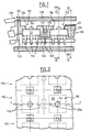
- a light emitting diode module intended to take the place of an elementary component, capable of being juxtaposed with identical modules, for the production of a signaling light, or a set of large area signal lights.
- such a module comprises four light-emitting diodes 110 of the "Brewster" type, available commercially.
- Each light-emitting diode or LED 110 comprises a body 112 of generally square outline and of trapezoidal cross section, in a conventional manner per se. At the center of the outer surface or front surface of the body is a protuberance 114 of substantially hemispherical shape. At the rear of the body 112 extend three metal tabs 116 for electrical connection, the cross section of which in a terminal region is reduced. As shown in FIG. 2, the body 112 of the LED 110 comprises two opposite lateral notches 118 of semi-circular section, intended to ensure the position of the LED in a well-determined position.
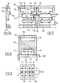
- a module according to this first embodiment comprises a frame 120 elongated along a longitudinal axis xx ( Figure 2), the cross section of which generally has the shape of an "H" ( Figure 4).
- This framework has two lateral uprights 122 interconnected, essentially at mid-height, by a cross member 124.
- This framework is preferably produced by molding plastic material.
- each housing 125 has two ribs lateral 125a (FIG. 2) intended to be engaged in the notches 118 of the body 112 of LEDs.
- plumb with the housings 125, four through openings 126 of generally circular section, opening at the center of said housings.
- the openings 126 are frustoconical, being flared upwards as illustrated, so as to allow all of the slightly divergent light flux to pass (the solid angle is typically 50 °) coming from the associated element 110.
- the frame 120 has two opposite end walls 128 (Figure 1) extending upward.
- a transparent element forming a cover 130 which is advantageously used as an optical element.
- This element 130 is elongated along the axis xx, over the entire length of the framework 120. It has along its four edges grooves 132 open on the side and intended to receive the free ends of the branches 122 and the end walls 128, to ensure a good mutual positioning of these elements.
- the element 130 may comprise, in relief on its internal or external surface, four Fresnel lenses aligned with the light exit openings 126 formed in the framework 120.
- the parts 110, 120 and 130 of the module are assembled by gluing, ultrasonic welding, or any other suitable technique, so as to ensure a perfect cohesion of module 100.
- the frame 120 has at its longitudinal edges and its terminal edges a draft angle a, for example of 5 °.
- This clearance angle makes it possible, as will be seen in detail below, to intimately juxtapose several LED modules with mutual angular offsets which can reach 10 ° in this case, which makes it possible to produce curved surfaces.
- a plurality of modules 100 according to the invention are intended to be mounted on a support plate 200, using means of which a particular embodiment will be described below.
- a module 100 is defined eight positions, denoted P1 to P8 in FIG. 5, located respectively on either side, in transverse direction, of an LED element 110.
- the plate 200 comprises, at well-defined locations, flexible tabs 210 which extend upwards and which each end with a tooth 212 projecting towards the side. Such a tab is illustrated in FIG. 3.
- the width of each tab is chosen to be equal to or slightly less than the width of the passage defined by the side wall 122 of the frame 120 in the "T" and "C” configurations.
- a frame 120 can present in its eight positions a pattern of eight assembly configurations chosen from a very large number (theoretically equal to 38) of possible reasons.
- a particular pattern of assembly configurations can constitute, according to another aspect of the present invention, a coding associated with the type of light-emitting diode module considered.
- a coding associated with the type of light-emitting diode module considered.
- the essential function of such "coding” is to provide polarization during the installation of a plurality of modules 100 on the plate 200, in particular avoiding that modules of different natures cannot be mixed, also avoiding that identical modules cannot be turned upside down, and avoiding that a location of the plate intended to receive a certain type of module cannot accidentally receive a module of a different type.
- a module cannot be positioned on the plate if a clipping tab 210 is located at the right of a "O" configuration. There is thus a keying between module and plate, to ensure that the plate receives the correct type of module.
- FIG. 6 illustrates, by the codes "C”, “T” and “O” mentioned above, seven patterns of particularly suitable configurations.
- Each motif comprises three configurations clipped “C” in a triangle, allowing anchoring on the plate at three points, that is to say by three clipping tabs 210, each longitudinal side comprising at least one of these configurations " VS". This gives the assembly great stability. We can thus identify seven different types of modules.
- the outer surface, facing the element 130, of the cross member 124 it is advantageous for the outer surface, facing the element 130, of the cross member 124 to be coated with a coating 121 of the aluminized type (by application of paint, vacuum metallization, etc. ..), so as to give the module, when it is switched off and viewed from the outside, as homogeneous an appearance as possible.
- a coating 121 of the aluminized type by application of paint, vacuum metallization, etc. ..
- modules comprising any number of such diodes. It is thus possible to design a set of elementary bricks, for example with 1, 2, 4, 8 and 12 diodes arranged in a single row, or also with 4, 6 or 8 diodes arranged side by side in two rows, etc. .., to produce illuminating surfaces (possibly curved) of completely arbitrary shapes and dimensions by a judicious choice of elementary bricks.
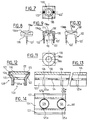
- FIGS. 7 to 11 illustrate a diode module of the "Brewster" type according to another embodiment of the invention.
- This module comprises a frame 120 and a covering element 130 formed in one piece, by molding of transparent plastic.
- the frame 120 is in this case limited to two legs 122 'which project downwards from the median regions on two opposite sides of the element 130, and which engage at least partially in the opposite lateral notches 118 of the LED element 110, identical to that described above.
- this module with a single "Brewster" diode (or, as a variant, with several diodes) can be done on a printed circuit (not shown), the pins of the LED element 110 and the free ends of the legs 122 ' can be engaged in appropriate holes in the printed circuit.
- the element 130 defines a plano-convex lens, its inner face 135, facing the element 110, being convex, while the part opposite to 136a of its outer face is flat, being bordered by a tapered tapered portion 136b. This produces a concentration, along the axis of the element 110, of the light flux that it emits.
- Figures 12 to 14 show another embodiment of a module according to the invention.
- an elongated frame 120 whose cross section has the general shape of an "H", with two lateral branches 122 and a cross member 124 in which are practiced a plurality of aligned openings 126, for example four in number.
- each LED element 110 is received not in a specific housing formed in the cross member 124, but in the cavity defined by the base of the lateral branches 122 and by the cross member 124 To this end, it is provided in the base part of said branches 122, in line with each respective opening 126 and on either side thereof, a semi-circular rib 125a able to engage in an associated notch 118 of the LED element 110.
- FIGS. 12 to 14 Another particularity of the module of FIGS. 12 to 14 resides in that the covering element 130, here provided on its outer surface with Fresnel rungs 137, is embedded between the two branches 122, grooves 123 being formed for this purpose in the outer terminal region of said branches.
- branches 122 of the framework 120 are essentially parallel to each other in the region of their base, but widen upwards beyond the crosspiece 124. It is thus, as previously, possible to produce domed illuminating surfaces .
- the components 110, 120 and 130 of the module are assembled by a conventional gluing or welding technique.
- An advantage specific to this embodiment resides in that it is possible to produce a profile of great length, in which frameworks 120 of various lengths can be cut, in order to produce modules with N elements 110.
- FIG. 15 schematically illustrates a possible mode of electrical connection of two modules 100 arranged in alignment with one another.
- Each module 100 comprises, at each longitudinal end face, a male pin 171 and a female pin 172 located in two well defined positions. At its opposite end, two male and female pins 171, 172 are also arranged in an inverted manner.
- a male pin 171 of a module engages in a female pin opposite 172 of the neighboring module, while a male pin 171 of said neighboring module engages in the female pin 172 of the first cited module.
- a bus type electrical supply circuit is thus produced which circulates in all the connected modules.
- FIGS 16a to 16c illustrate schematically other types of electrical connections possible.
- each “Brewster” type diode 110 is individually connected to a supply circuit by two flexible conductors 301, 302, the ends of which may have lugs (not shown) to be crimped on the pins of said diode.
- FIG. 16b shows a printed circuit 140 received in a cavity in the frame 120, in a manner completely analogous to the case in FIGS. 1 to 6.
- This printed circuit, to which N LED elements 110 are connected is individually connected by two conductors 303, 304 to a supply circuit.
- FIG. 16c illustrates a solution which also uses a printed circuit 140.
- this printed circuit comprises two male conductive pins 141, 142 which protrude, in well determined positions, towards its side opposite to the LED elements 110.
- the plate 200 carries meanwhile female connection elements 221, 222 intended to receive said male pins 141, 142.
- these female connection elements can be part of a circuit called "cut circuit", well known per se for the distribution of supply voltages to filament lamps of a block of traffic lights, this cut-out circuit being generally indicated at 220.
- these male-female electrical connection means can advantageously be used for the mechanical fixing of each module 100 on the plate 200.
- the position of the pair of male pins 141, 142 can vary according to the type of module considered, so as to ensure polarization in the same spirit, but by different technical means, than in the case of the modules produced according to Figures 1 to 6.
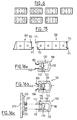
- Figure 17 schematically illustrates, in front elevation, a block of rear vehicle signal lights automotive using light emitting diode modules as described above.
- Figures 18 to 22 illustrate different sections through this block of lights.
- the light unit 400 is separated into two distinct parts, namely a curved outer part 400a, called the wing return, and an inner part (relative to the central axis of the vehicle), of generally flat.
- the external part 400a comprises a bottom 410a and a sight glass or globe 420a, of curved shape, situated at a substantially constant distance from each other.
- the sight glass 420a is mounted on the bottom 410a using a peripheral re-entrant flange 422a, engaged in a complementary groove 412a formed at the periphery of the bottom 410a.
- a seal (not referenced) is conventionally interposed between these two parts.
- the external part 400a comprises two illuminating surfaces P1 and P2 produced exclusively using modules with light-emitting diodes 100 for example as described above. These are modules with four diodes 110.
- the bottom 410a of said part 400a plays the role of the plate such as 200 described with reference to FIGS. 1 to 6, for example comprising clipping means (not shown) for mounting the individual modules.
- the upper range P1 corresponds to a stop light, red
- the lower range P2, of lower height corresponds to a direction indicator flashing light, amber.
- the modules 100 are offset in position relative to each other so as to match the inclination of the bottom 410a and the indicator 420a.
- the two areas P1 and P2 are separated by a thin area 414a made of material, projecting forward, during the molding of the bottom 410a.
- the light 420a can be made of colorless transparent plastic, or of a tinted plastic (for example smoke) so as not to substantially alter the colors generated .
- light-emitting diode modules makes it possible to produce lights of an extremely limited depth, typically 20 to 30 mm, while having illuminating surfaces whose levels of illumination are extremely homogeneous.
- the interior part 400b of the block of lights comprises, in a manner similar to the part 400a, a bottom 410b and an indicator 420b assembled in the same way.
- This part 400b defines two illuminating areas P3 and P4.
- the part P3 intended for example to fulfill the position light function, is also produced using modules with light-emitting diodes, but in a manner different from the ranges P1 and P2. More specifically, there is provided in the lower region of the cavity corresponding to the area P3 a single row of several modules 100 oriented so as to emit the light upwards.
- the surface of the bottom 410b facing the sight glass 420b includes a special treatment so as to fold out, while diffusing it, the light received from the modules 100. In the embodiment of FIGS. 17 to 22, this treatment consists of a shot.
- this treatment consists of a shot.
- this treatment can consist of a series of concave ridges 416b (or even convex ridges) extending horizontally over the surface of the bottom 410b.
- the sight glass 420b can be for example transparent colorless or tinted (smoked).
- an opaque coating for example black, is formed on the interior surface of the sight glass 420b at the level of the row of modules 100, so as to mask said modules when the block of lights is observed from the outside.
- the other illuminating surface P4 of part 400b corresponds for example to the reversing light function or to the rear fog light function. It is carried out here in a conventional manner: the bottom 410b defines at the level of the range P4 a reflector of the parabolic type, which cooperates with a lamp 430 to form a concentrated signaling beam.
- the indicator 420b, at the level of the area P4, can have zones 424b, 425b which are alternately colorless and translucent in smoke color, so as to present a relatively homogeneous appearance with the portion of the indicator corresponding to the area P3 while attenuating not excessively light radiation.
- the reference 440 schematically indicates a supply circuit for the row of modules 100 lighting up in the range P3.
- lights or blocks of lights can be produced using light-emitting diode modules to obtain completely arbitrary contours and shapes.
- additional modules with a single diode or with two diodes, it is understood that it is possible to closely follow any curved contours.
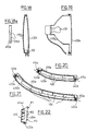
- FIG. 23 represents the inclined rear window 502 of the vehicle, a body element which overcomes it being designated by 504.
- the raised brake light comprises a cover 510 of cross section in the general shape of "L", of which an essentially vertical branch 510a is pressed against the element 504 and of which a horizontal branch 510b is pressed against the bezel 502.
- a brake light which comprises a plurality of modules as described with reference to Figures 12 to 14, arranged in a single horizontal row.
- the modules are arranged in a housing or shell 520 extending horizontally and comprising two half-shells 520a and 520b, the rear half-shell (relative to the direction of light emission) being opaque and comprising means (not shown) for its attachment to the branch 510b of the cover.
- the front half-shell 520b is made of colorless transparent plastic material (or smoke), so as to let pass the light emitted by the LED elements 110 and passing through the covering element or elements 130.
- a printed circuit is received in the half-shell 520a, the connection lugs 116 of the elements 110 being soldered to this circuit.
- This half-shell 520a also houses the flexible electrical connection conductors (not shown).
- the half-shell 520b receives the modules 100, and it has for this purpose, in the thickness of its upper and lower walls, shoulders 522b allowing the setting of the front edge (relative to the direction of emission) of each module.
- the various components of the light are preferably assembled by gluing.
Landscapes
- Engineering & Computer Science (AREA)
- General Engineering & Computer Science (AREA)
- Physics & Mathematics (AREA)
- Microelectronics & Electronic Packaging (AREA)
- Optics & Photonics (AREA)
- Mechanical Engineering (AREA)
- Non-Portable Lighting Devices Or Systems Thereof (AREA)
- Lighting Device Outwards From Vehicle And Optical Signal (AREA)
- Led Device Packages (AREA)
Applications Claiming Priority (2)
| Application Number | Priority Date | Filing Date | Title |
|---|---|---|---|
| FR9213089A FR2697485B1 (fr) | 1992-11-02 | 1992-11-02 | Feu de signalisation à éléments lumineux modulaires, pour véhicule automobile. |
| FR9213089 | 1992-11-02 |
Publications (2)
| Publication Number | Publication Date |
|---|---|
| EP0596783A1 true EP0596783A1 (de) | 1994-05-11 |
| EP0596783B1 EP0596783B1 (de) | 1997-03-12 |
Family
ID=9435079
Family Applications (1)
| Application Number | Title | Priority Date | Filing Date |
|---|---|---|---|
| EP93402661A Expired - Lifetime EP0596783B1 (de) | 1992-11-02 | 1993-10-29 | Signalleuchte mit modularen Lichteinheiten für Fahrzeuge |
Country Status (7)
| Country | Link |
|---|---|
| US (1) | US5436809A (de) |
| EP (1) | EP0596783B1 (de) |
| JP (1) | JPH0891116A (de) |
| BR (1) | BR9304418A (de) |
| DE (1) | DE69308735T2 (de) |
| ES (1) | ES2100497T3 (de) |
| FR (1) | FR2697485B1 (de) |
Cited By (4)
| Publication number | Priority date | Publication date | Assignee | Title |
|---|---|---|---|---|
| GB2292450A (en) * | 1994-08-16 | 1996-02-21 | Sepe Sehati | Safety device for a vehicle |
| DE29602125U1 (de) * | 1996-02-08 | 1996-04-18 | Hella KG Hueck & Co., 59557 Lippstadt | Signalleuchte für Fahrzeuge |
| EP1633597B1 (de) * | 2003-05-28 | 2008-07-02 | Volkswagen AG | Beleuchtungsvorrichtung für fahrzeuge mit einem leuchtdioden umfassenden leuchtmodul |
| EP2169300A1 (de) * | 2008-09-29 | 2010-03-31 | Cemm Thome | Lampe mit LED und Crimpkontakten |
Families Citing this family (119)
| Publication number | Priority date | Publication date | Assignee | Title |
|---|---|---|---|---|
| US6590502B1 (en) | 1992-10-12 | 2003-07-08 | 911Ep, Inc. | Led warning signal light and movable support |
| US5607227A (en) * | 1993-08-27 | 1997-03-04 | Sanyo Electric Co., Ltd. | Linear light source |
| US5580156A (en) * | 1994-09-27 | 1996-12-03 | Koito Manufacturing Co., Ltd. | Marker apparatus |
| US5660461A (en) * | 1994-12-08 | 1997-08-26 | Quantum Devices, Inc. | Arrays of optoelectronic devices and method of making same |
| US5567036A (en) * | 1995-04-05 | 1996-10-22 | Grote Industries, Inc. | Clearance and side marker lamp |
| JP2909023B2 (ja) * | 1996-05-01 | 1999-06-23 | 日吉電子株式会社 | 長尺発光装置 |
| JP3009626B2 (ja) * | 1996-05-20 | 2000-02-14 | 日吉電子株式会社 | Led発光球 |
| US6045243A (en) * | 1996-08-28 | 2000-04-04 | K.W. Muth Company, Inc. | Mirror assembly |
| US5788357A (en) * | 1996-08-28 | 1998-08-04 | K. W. Muth Company, Inc. | Mirror assembly |
| US5877682A (en) * | 1996-08-30 | 1999-03-02 | Mack Trucks, Inc. | Vehicular lamp and method |
| US5745043A (en) * | 1996-10-15 | 1998-04-28 | Clarke Industries, Inc. | Indicator junction module for pressure washer |
| CA2299532C (en) | 1997-08-07 | 2008-07-08 | Decoma International Inc. | Thin light managing system for directing and distributing light from one or more light sources and method for making optics structures for use in the system |
| GB2330679B (en) * | 1997-10-21 | 2002-04-24 | 911 Emergency Products Inc | Warning signal light |
| US6057127A (en) * | 1998-01-29 | 2000-05-02 | Heska Corporation | Equine Fc epsilon receptor alpha chain nucleic acid molecules and uses thereof |
| DE19818403A1 (de) * | 1998-04-24 | 1999-10-28 | Horn Hannes Schulze | Beleuchtungssystem mit Niederspannungs-Leuchten und -Lampen |
| DE19822179A1 (de) * | 1998-05-16 | 1999-11-18 | Volkswagen Ag | Scheinwerfer oder Leuchte |
| DE19837553A1 (de) * | 1998-08-19 | 2000-02-24 | Hella Kg Hueck & Co | Fahrzeugleuchte |
| US7066628B2 (en) * | 2001-03-29 | 2006-06-27 | Fiber Optic Designs, Inc. | Jacketed LED assemblies and light strings containing same |
| US6005724A (en) * | 1998-10-05 | 1999-12-21 | K. W. Muth Company, Inc. | Mirror coating, mirror utilizing same, and a mirror assembly |
| US6257746B1 (en) | 1998-11-03 | 2001-07-10 | K. W. Muth Company, Inc. | Signalling assembly |
| US7931390B2 (en) * | 1999-02-12 | 2011-04-26 | Fiber Optic Designs, Inc. | Jacketed LED assemblies and light strings containing same |
| JP3920486B2 (ja) * | 1999-02-23 | 2007-05-30 | 株式会社小糸製作所 | 車両用灯具 |
| DE19908040A1 (de) * | 1999-02-24 | 2000-08-31 | Diehl Stiftung & Co | Einrichtung zur Beleuchtung von Räumen, Körpern oder Flächen |
| US6614359B2 (en) | 1999-04-06 | 2003-09-02 | 911 Emergency Products, Inc. | Replacement led lamp assembly and modulated power intensity for light source |
| US6462669B1 (en) | 1999-04-06 | 2002-10-08 | E. P . Survivors Llc | Replaceable LED modules |
| WO2000074973A1 (en) | 1999-06-08 | 2000-12-14 | 911 Emergency Products, Inc. | Rotational led reflector |
| US6700502B1 (en) | 1999-06-08 | 2004-03-02 | 911Ep, Inc. | Strip LED light assembly for motor vehicle |
| US6705745B1 (en) | 1999-06-08 | 2004-03-16 | 911Ep, Inc. | Rotational led reflector |
| US6367949B1 (en) | 1999-08-04 | 2002-04-09 | 911 Emergency Products, Inc. | Par 36 LED utility lamp |
| DE19941524A1 (de) * | 1999-09-01 | 2001-03-08 | Hella Kg Hueck & Co | Leuchte für Fahrzeuge |
| DE10012734C1 (de) * | 2000-03-16 | 2001-09-27 | Bjb Gmbh & Co Kg | Illuminationsbausatz für Beleuchtungs-, Anzeige- oder Hinweiszwecke sowie Steckverbinder für einen solchen Illuminationsbausatz |
| US6642840B2 (en) | 2000-07-28 | 2003-11-04 | Lang-Mekra North Amicica, Llc | Rearview mirror assembly with monitor |
| DE10036875A1 (de) | 2000-07-28 | 2002-02-28 | Mekra Lang Gmbh & Co Kg | Rückspiegel, insbesondere für Nutzfahrzeuge mit Kamera und Monitor |
| US7439847B2 (en) | 2002-08-23 | 2008-10-21 | John C. Pederson | Intelligent observation and identification database system |
| WO2002041276A2 (en) * | 2000-11-15 | 2002-05-23 | Snowy Village, Inc. | Led warning light and communication system |
| US8188878B2 (en) | 2000-11-15 | 2012-05-29 | Federal Law Enforcement Development Services, Inc. | LED light communication system |
| DE20105791U1 (de) | 2001-04-03 | 2002-08-14 | MEKRA Lang GmbH & Co. KG, 90765 Fürth | Spiegelanordnung für Kraftfahrzeuge |
| DE20106977U1 (de) | 2001-04-23 | 2002-08-29 | Mekra Lang Gmbh & Co Kg | Warneinrichtung in Kraftfahrzeugen |
| US6871981B2 (en) * | 2001-09-13 | 2005-03-29 | Heads Up Technologies, Inc. | LED lighting device and system |
| DE10147268A1 (de) * | 2001-09-26 | 2003-04-24 | Kastriot Merlaku | Rückwärtslicht-Scheinwerfer für das Fahrzeug mit Leuchtdioden |
| US6550950B1 (en) | 2001-11-27 | 2003-04-22 | Robert A. Fernandez | Light emitting diodes vehicle lamp |
| DE10239840A1 (de) * | 2002-08-29 | 2004-04-01 | Volkswagen Ag | Vorrichtung zum Befestigen einer Sensoreinrichtung in einem Kraftfahrzeug |
| US6678171B1 (en) | 2002-10-24 | 2004-01-13 | Guide Corporation | Fastening arrangement for light emitting diode metal array |
| TW578310B (en) * | 2003-04-02 | 2004-03-01 | Au Optronics Corp | Low temperature poly silicon thin film transistor and method of forming poly silicon layer of the same |
| US6860620B2 (en) * | 2003-05-09 | 2005-03-01 | Agilent Technologies, Inc. | Light unit having light emitting diodes |
| US20050001562A1 (en) * | 2003-07-02 | 2005-01-06 | 911Ep, Inc. | LED compensation circuit |
| US7008091B2 (en) | 2003-12-18 | 2006-03-07 | K.W. Muth Company, Inc. | Electromagnetic radiation assembly |
| DE102004036340A1 (de) * | 2004-07-27 | 2006-03-23 | Schmitz Gotha Fahrzeugwerke Gmbh | Heckleuchtenanordnung für Lastfahrzeuge, insbesondere Anhänger |
| US7205887B2 (en) * | 2004-08-23 | 2007-04-17 | T.Y.C. Brother Industrial Co., Ltd. | Turn indicator unit for a relay-controlled flasher |
| US7850362B2 (en) * | 2004-11-10 | 2010-12-14 | 1 Energy Solutions, Inc. | Removable LED lamp holder with socket |
| US7850361B2 (en) * | 2004-11-10 | 2010-12-14 | 1 Energy Solutions, Inc. | Removable LED lamp holder |
| US20060125615A1 (en) * | 2004-11-29 | 2006-06-15 | Song Won M | Vehicle accelerator and brake indicators |
| US20060192665A1 (en) * | 2005-02-15 | 2006-08-31 | Song Won M | System for improving the visibility of a vehicle during reduced visibility conditions |
| US20060125616A1 (en) * | 2004-11-29 | 2006-06-15 | Song Won M | Method for a changing safety signaling system |
| US7712948B2 (en) * | 2005-02-02 | 2010-05-11 | Koninklijke Philips Electronics N.V. | Light-source module and holder therefor |
| US8016440B2 (en) * | 2005-02-14 | 2011-09-13 | 1 Energy Solutions, Inc. | Interchangeable LED bulbs |
| US7241037B2 (en) * | 2005-03-23 | 2007-07-10 | K.W. Muth Company | Signaling assembly |
| US7327321B2 (en) * | 2005-06-27 | 2008-02-05 | K.W. Muth Company, Inc. | Electromagnetic radiation assembly |
| US20070025109A1 (en) | 2005-07-26 | 2007-02-01 | Yu Jing J | C7, C9 LED bulb and embedded PCB circuit board |
| US7265496B2 (en) * | 2005-09-23 | 2007-09-04 | Fiber Optic Designs, Inc. | Junction circuit for LED lighting chain |
| US7276858B2 (en) | 2005-10-28 | 2007-10-02 | Fiber Optic Designs, Inc. | Decorative lighting string with stacked rectification |
| US7250730B1 (en) * | 2006-01-17 | 2007-07-31 | Fiber Optic Designs, Inc. | Unique lighting string rectification |
| US8083393B2 (en) | 2006-02-09 | 2011-12-27 | 1 Energy Solutions, Inc. | Substantially inseparable LED lamp assembly |
| JP4573128B2 (ja) * | 2006-03-14 | 2010-11-04 | ミネベア株式会社 | 面状照明装置 |
| US20080025024A1 (en) * | 2006-07-31 | 2008-01-31 | Jingjing Yu | Parallel-series led light string |
| US7963670B2 (en) * | 2006-07-31 | 2011-06-21 | 1 Energy Solutions, Inc. | Bypass components in series wired LED light strings |
| US20080062721A1 (en) * | 2006-09-07 | 2008-03-13 | Chunghwa Picture Tubes, Ltd. | Liquid crystal display and back light module thereof |
| US9414458B2 (en) | 2007-05-24 | 2016-08-09 | Federal Law Enforcement Development Services, Inc. | LED light control assembly and system |
| US20090003832A1 (en) | 2007-05-24 | 2009-01-01 | Federal Law Enforcement Development Services, Inc. | Led light broad band over power line communication system |
| US9258864B2 (en) | 2007-05-24 | 2016-02-09 | Federal Law Enforcement Development Services, Inc. | LED light control and management system |
| US9100124B2 (en) | 2007-05-24 | 2015-08-04 | Federal Law Enforcement Development Services, Inc. | LED Light Fixture |
| US9455783B2 (en) | 2013-05-06 | 2016-09-27 | Federal Law Enforcement Development Services, Inc. | Network security and variable pulse wave form with continuous communication |
| US11265082B2 (en) | 2007-05-24 | 2022-03-01 | Federal Law Enforcement Development Services, Inc. | LED light control assembly and system |
| US9294198B2 (en) | 2007-05-24 | 2016-03-22 | Federal Law Enforcement Development Services, Inc. | Pulsed light communication key |
| US7559672B1 (en) * | 2007-06-01 | 2009-07-14 | Inteled Corporation | Linear illumination lens with Fresnel facets |
| US7784993B2 (en) | 2007-07-13 | 2010-08-31 | 1 Energy Solutions, Inc. | Watertight LED lamp |
| KR101395059B1 (ko) * | 2007-11-29 | 2014-05-14 | 삼성디스플레이 주식회사 | 백라이트 유닛 및 이를 포함한 액정 표시 장치 |
| US8376606B2 (en) * | 2008-04-08 | 2013-02-19 | 1 Energy Solutions, Inc. | Water resistant and replaceable LED lamps for light strings |
| US7883261B2 (en) * | 2008-04-08 | 2011-02-08 | 1 Energy Solutions, Inc. | Water-resistant and replaceable LED lamps |
| US20100097803A1 (en) * | 2008-10-20 | 2010-04-22 | Wu Ming-Chang | Multiple Light Source Surface Packaging Structure |
| US8314564B2 (en) | 2008-11-04 | 2012-11-20 | 1 Energy Solutions, Inc. | Capacitive full-wave circuit for LED light strings |
| US8890773B1 (en) | 2009-04-01 | 2014-11-18 | Federal Law Enforcement Development Services, Inc. | Visible light transceiver glasses |
| CN201391793Y (zh) * | 2009-04-20 | 2010-01-27 | 喻北京 | Led灯泡的新型散热结构 |
| US8836224B2 (en) * | 2009-08-26 | 2014-09-16 | 1 Energy Solutions, Inc. | Compact converter plug for LED light strings |
| US8651689B2 (en) * | 2010-09-20 | 2014-02-18 | Shenzhen China Star Optoelectronics Technology Co., Ltd | Light emitting diode light bar structure having heat dissipation function |
| WO2012097291A1 (en) | 2011-01-14 | 2012-07-19 | Federal Law Enforcement Development Services, Inc. | Method of providing lumens and tracking of lumen consumption |
| US9194566B2 (en) | 2012-06-08 | 2015-11-24 | Lg Innotek Co., Ltd. | Lamp unit and vehicle lamp apparatus using the same |
| US9890916B2 (en) * | 2012-06-08 | 2018-02-13 | Lg Innotek Co., Ltd. | Lamp unit and vehicle using the same |
| US8876322B2 (en) | 2012-06-20 | 2014-11-04 | Journée Lighting, Inc. | Linear LED module and socket for same |
| KR102080610B1 (ko) | 2012-11-14 | 2020-02-25 | 엘지이노텍 주식회사 | 램프 및 그를 이용한 차량 램프 장치 |
| US9565782B2 (en) | 2013-02-15 | 2017-02-07 | Ecosense Lighting Inc. | Field replaceable power supply cartridge |
| WO2014160096A1 (en) | 2013-03-13 | 2014-10-02 | Federal Law Enforcement Development Services, Inc. | Led light control and management system |
| US9976710B2 (en) | 2013-10-30 | 2018-05-22 | Lilibrand Llc | Flexible strip lighting apparatus and methods |
| US20150198941A1 (en) | 2014-01-15 | 2015-07-16 | John C. Pederson | Cyber Life Electronic Networking and Commerce Operating Exchange |
| US10477636B1 (en) | 2014-10-28 | 2019-11-12 | Ecosense Lighting Inc. | Lighting systems having multiple light sources |
| US9869450B2 (en) | 2015-02-09 | 2018-01-16 | Ecosense Lighting Inc. | Lighting systems having a truncated parabolic- or hyperbolic-conical light reflector, or a total internal reflection lens; and having another light reflector |
| US11306897B2 (en) | 2015-02-09 | 2022-04-19 | Ecosense Lighting Inc. | Lighting systems generating partially-collimated light emissions |
| US9651227B2 (en) | 2015-03-03 | 2017-05-16 | Ecosense Lighting Inc. | Low-profile lighting system having pivotable lighting enclosure |
| US9746159B1 (en) | 2015-03-03 | 2017-08-29 | Ecosense Lighting Inc. | Lighting system having a sealing system |
| US9568665B2 (en) | 2015-03-03 | 2017-02-14 | Ecosense Lighting Inc. | Lighting systems including lens modules for selectable light distribution |
| US9651216B2 (en) | 2015-03-03 | 2017-05-16 | Ecosense Lighting Inc. | Lighting systems including asymmetric lens modules for selectable light distribution |
| USD785218S1 (en) | 2015-07-06 | 2017-04-25 | Ecosense Lighting Inc. | LED luminaire having a mounting system |
| USD782093S1 (en) | 2015-07-20 | 2017-03-21 | Ecosense Lighting Inc. | LED luminaire having a mounting system |
| USD782094S1 (en) | 2015-07-20 | 2017-03-21 | Ecosense Lighting Inc. | LED luminaire having a mounting system |
| US9651232B1 (en) | 2015-08-03 | 2017-05-16 | Ecosense Lighting Inc. | Lighting system having a mounting device |
| US20170048953A1 (en) | 2015-08-11 | 2017-02-16 | Federal Law Enforcement Development Services, Inc. | Programmable switch and system |
| EP3427307A4 (de) | 2016-03-08 | 2020-01-01 | Lilibrand LLC | Beleuchtungssystem mit linsenanordnung |
| CN110998880A (zh) | 2017-01-27 | 2020-04-10 | 莉莉布兰德有限责任公司 | 具有高显色指数和均匀平面照明的照明系统 |
| US12388056B1 (en) | 2017-01-27 | 2025-08-12 | Korrus, Inc. | Linear lighting systems and processes |
| US20180328552A1 (en) | 2017-03-09 | 2018-11-15 | Lilibrand Llc | Fixtures and lighting accessories for lighting devices |
| FR3071039B1 (fr) * | 2017-09-12 | 2019-08-30 | Valeo Vision | Dispositif lumineux a faible epaisseur et eclairage homogene |
| WO2019213299A1 (en) | 2018-05-01 | 2019-11-07 | Lilibrand Llc | Lighting systems and devices with central silicone module |
| WO2020131933A1 (en) | 2018-12-17 | 2020-06-25 | Lilibrand Llc | Strip lighting systems which comply with ac driving power |
| EP3956925A1 (de) * | 2019-04-18 | 2022-02-23 | Lumileds Holding B.V. | Beleuchtungsvorrichtung |
| US11300880B2 (en) * | 2019-12-09 | 2022-04-12 | Nanya Technology Corporation | Coating system and calibration method thereof |
| EP4501706A3 (de) | 2020-01-09 | 2025-06-04 | Electronic Controls Company | Flexible richtungsabhängige warnleuchte für fahrzeuge |
| USD1010179S1 (en) | 2020-01-09 | 2024-01-02 | Electronic Controls Company | Flexible directional vehicle warning light |
| EP4265961B1 (de) * | 2022-04-22 | 2025-05-28 | Marelli Automotive Lighting Italy S.p.A. Con Socio Unico | Kfz-beleuchtungseinrichtung und zugehöriges herstellungsverfahren |
| EP4524460A1 (de) * | 2023-09-13 | 2025-03-19 | PO LIGHTING CZECH s.r.o. | Kraftfahrzeugbeleuchtungsvorrichtung mit verbessertem aspekt |
Citations (7)
| Publication number | Priority date | Publication date | Assignee | Title |
|---|---|---|---|---|
| DE2941634A1 (de) * | 1978-10-17 | 1980-04-30 | Stanley Electric Co Ltd | Farbiges licht emittierende anzeigeeinrichtung |
| WO1984000799A1 (fr) * | 1982-08-20 | 1984-03-01 | Bosch Gmbh Robert | Lampe pour vehicule automobile constituee de diodes luminescentes ou de puces de diodes luminescentes |
| JPS61119444A (ja) * | 1984-11-16 | 1986-06-06 | Stanley Electric Co Ltd | 車両用標識燈 |
| EP0326668A2 (de) * | 1988-02-02 | 1989-08-09 | Stanley Electric Co., Ltd. | Kombinierte Schlussleuchteneinrichtung für Kraftfahrzeuge |
| EP0328088A2 (de) * | 1988-02-10 | 1989-08-16 | MENTOR GMBH & CO. | Reflektor-Leuchte |
| EP0434471A1 (de) * | 1989-12-21 | 1991-06-26 | Dialight Corporation | Oberflächenmontiertes LED-Gehäuse |
| US5038255A (en) * | 1989-09-09 | 1991-08-06 | Stanley Electric Co., Ltd. | Vehicle lamp |
Family Cites Families (8)
| Publication number | Priority date | Publication date | Assignee | Title |
|---|---|---|---|---|
| JPS5976304A (ja) * | 1982-10-20 | 1984-05-01 | ショーボンド建設株式会社 | 発光ブロツク及び発光表示装置 |
| US4733335A (en) * | 1984-12-28 | 1988-03-22 | Koito Manufacturing Co., Ltd. | Vehicular lamp |
| US4963933A (en) * | 1988-10-05 | 1990-10-16 | Hewlett-Packard Company | LED illuminator bar for copier |
| JPH0612564Y2 (ja) * | 1989-02-09 | 1994-03-30 | 株式会社小糸製作所 | 自動車用信号灯 |
| US5008788A (en) * | 1990-04-02 | 1991-04-16 | Electronic Research Associates, Inc. | Multi-color illumination apparatus |
| US5241457A (en) * | 1991-01-18 | 1993-08-31 | Nippon Sheet Glass Co., Ltd. | Rear window stop lamp for motor vehicles |
| US5174649B1 (en) * | 1991-07-17 | 1998-04-14 | Precision Solar Controls Inc | Led lamp including refractive lens element |
| US5337225A (en) * | 1993-01-06 | 1994-08-09 | The Standard Products Company | Lighting strip system |
-
1992
- 1992-11-02 FR FR9213089A patent/FR2697485B1/fr not_active Expired - Fee Related
-
1993
- 1993-10-29 EP EP93402661A patent/EP0596783B1/de not_active Expired - Lifetime
- 1993-10-29 US US08/144,831 patent/US5436809A/en not_active Expired - Fee Related
- 1993-10-29 DE DE69308735T patent/DE69308735T2/de not_active Expired - Fee Related
- 1993-10-29 BR BR9304418A patent/BR9304418A/pt not_active Application Discontinuation
- 1993-10-29 ES ES93402661T patent/ES2100497T3/es not_active Expired - Lifetime
- 1993-11-02 JP JP27460393A patent/JPH0891116A/ja active Pending
Patent Citations (7)
| Publication number | Priority date | Publication date | Assignee | Title |
|---|---|---|---|---|
| DE2941634A1 (de) * | 1978-10-17 | 1980-04-30 | Stanley Electric Co Ltd | Farbiges licht emittierende anzeigeeinrichtung |
| WO1984000799A1 (fr) * | 1982-08-20 | 1984-03-01 | Bosch Gmbh Robert | Lampe pour vehicule automobile constituee de diodes luminescentes ou de puces de diodes luminescentes |
| JPS61119444A (ja) * | 1984-11-16 | 1986-06-06 | Stanley Electric Co Ltd | 車両用標識燈 |
| EP0326668A2 (de) * | 1988-02-02 | 1989-08-09 | Stanley Electric Co., Ltd. | Kombinierte Schlussleuchteneinrichtung für Kraftfahrzeuge |
| EP0328088A2 (de) * | 1988-02-10 | 1989-08-16 | MENTOR GMBH & CO. | Reflektor-Leuchte |
| US5038255A (en) * | 1989-09-09 | 1991-08-06 | Stanley Electric Co., Ltd. | Vehicle lamp |
| EP0434471A1 (de) * | 1989-12-21 | 1991-06-26 | Dialight Corporation | Oberflächenmontiertes LED-Gehäuse |
Non-Patent Citations (1)
| Title |
|---|
| PATENT ABSTRACTS OF JAPAN vol. 10, no. 307 (M - 527)<2363> 18 October 1986 (1986-10-18) * |
Cited By (5)
| Publication number | Priority date | Publication date | Assignee | Title |
|---|---|---|---|---|
| GB2292450A (en) * | 1994-08-16 | 1996-02-21 | Sepe Sehati | Safety device for a vehicle |
| DE29602125U1 (de) * | 1996-02-08 | 1996-04-18 | Hella KG Hueck & Co., 59557 Lippstadt | Signalleuchte für Fahrzeuge |
| EP1633597B1 (de) * | 2003-05-28 | 2008-07-02 | Volkswagen AG | Beleuchtungsvorrichtung für fahrzeuge mit einem leuchtdioden umfassenden leuchtmodul |
| EP2169300A1 (de) * | 2008-09-29 | 2010-03-31 | Cemm Thome | Lampe mit LED und Crimpkontakten |
| FR2936678A1 (fr) * | 2008-09-29 | 2010-04-02 | Cemm Thome | Lampe a diode electroluminescente |
Also Published As
| Publication number | Publication date |
|---|---|
| FR2697485B1 (fr) | 1995-01-20 |
| DE69308735D1 (de) | 1997-04-17 |
| FR2697485A1 (fr) | 1994-05-06 |
| DE69308735T2 (de) | 1997-08-21 |
| ES2100497T3 (es) | 1997-06-16 |
| EP0596783B1 (de) | 1997-03-12 |
| BR9304418A (pt) | 1994-05-10 |
| JPH0891116A (ja) | 1996-04-09 |
| US5436809A (en) | 1995-07-25 |
Similar Documents
| Publication | Publication Date | Title |
|---|---|---|
| EP0596783B1 (de) | Signalleuchte mit modularen Lichteinheiten für Fahrzeuge | |
| EP0596782B1 (de) | Modulare Einheit für Signalleuchte eines Fahrzeugs | |
| EP0633163B1 (de) | Signalleuchte für ein Kraftfahrzeug mit Elektrolumineszenzdioden und Kombinationsleuchte mit derartigen Signalleuchten | |
| EP0762049B1 (de) | Signalleuchte mit mehreren in Reihe angeordneten Lichtquellen, insbesondere komplementäre Bremsleuchte für Kraftfahrzeuge | |
| FR2707222A1 (fr) | Feu de signalisation perfectionné à diodes électroluminescentes. | |
| FR2699471A1 (fr) | Dispositif lumineux pour véhicules automobiles dont la lampe comprend plusieurs sources de lumière à semi-conducteur. | |
| FR2605713A1 (fr) | Lampe de signalisation, particulierement pour des vehicules a moteur | |
| CA2075272A1 (fr) | Feu de signalisation a elements electroluminescents, notamment pour vehicule automobile | |
| FR2776595A1 (fr) | Feu de signalisation comprenant plusieurs sources lumineuses | |
| FR3056699A1 (fr) | Module lumineux et dispositif lumineux pour vehicule auto-mobile comportant un tel module lumineux | |
| EP0632228B1 (de) | Stylistisches oder optisches Element- mit glänzendem Aussehen und neutraler Farbe- für Kfz-Beleuchtungs- oder Anzeige-Scheinwerfer | |
| FR2557046A1 (fr) | Panneau pour vehicules a moteur | |
| EP2921771A1 (de) | Leuchtmodul für tagfahrlicht eines kraftfahrzeugs | |
| EP0211742B1 (de) | Signalleuchten, insbesondere für Kraftfahrzeuge | |
| EP0784185A1 (de) | Signalleuchte mit einer Zwischenscheibe zur optischen Behandlung des Lichstrahles und für stilistische Gründe sowie Herstellungsverfahren derselben | |
| EP0764812B1 (de) | Kraftfahrzeugsignalleuchte mit tiefem Aussehen | |
| FR2685440A1 (fr) | Glace pour dispositif optique de signalisation equipee d'elements pseudo-catadioptriques. | |
| EP0648969B1 (de) | Anzeigeleuchte mit einer Mehrzahl von Lichtquellen niedriger Leistung und mit verbesserter Optik | |
| EP4090556B1 (de) | Karosserieelement, das vereinfachte ausrüstungsbefestigungsmittel enthält, und fahrzeug, das ein solches karosserieelement umfasst | |
| FR2857434A1 (fr) | Feu de signalisation pour vehicule | |
| EP0758070A1 (de) | Signalleuchte mit gleichmässigem Erscheinungsbild | |
| EP0274315B1 (de) | Signaleinheit für Kraftfahrzeuge mit zwei abgestumpften leuchtenden Flächen | |
| FR3153397A1 (fr) | Dispositif lumineux pour véhicule | |
| FR2785973A1 (fr) | Feu de signalisation pour vehicule | |
| WO2025045798A1 (fr) | Module d'éclairage pour un véhicule automobile |
Legal Events
| Date | Code | Title | Description |
|---|---|---|---|
| PUAI | Public reference made under article 153(3) epc to a published international application that has entered the european phase |
Free format text: ORIGINAL CODE: 0009012 |
|
| AK | Designated contracting states |
Kind code of ref document: A1 Designated state(s): DE ES GB IT |
|
| 17P | Request for examination filed |
Effective date: 19940912 |
|
| 17Q | First examination report despatched |
Effective date: 19951102 |
|
| GRAG | Despatch of communication of intention to grant |
Free format text: ORIGINAL CODE: EPIDOS AGRA |
|
| GRAH | Despatch of communication of intention to grant a patent |
Free format text: ORIGINAL CODE: EPIDOS IGRA |
|
| GRAH | Despatch of communication of intention to grant a patent |
Free format text: ORIGINAL CODE: EPIDOS IGRA |
|
| GRAA | (expected) grant |
Free format text: ORIGINAL CODE: 0009210 |
|
| AK | Designated contracting states |
Kind code of ref document: B1 Designated state(s): DE ES GB IT |
|
| REF | Corresponds to: |
Ref document number: 69308735 Country of ref document: DE Date of ref document: 19970417 |
|
| GBT | Gb: translation of ep patent filed (gb section 77(6)(a)/1977) |
Effective date: 19970422 |
|
| ITF | It: translation for a ep patent filed | ||
| REG | Reference to a national code |
Ref country code: ES Ref legal event code: FG2A Ref document number: 2100497 Country of ref document: ES Kind code of ref document: T3 |
|
| PLBE | No opposition filed within time limit |
Free format text: ORIGINAL CODE: 0009261 |
|
| STAA | Information on the status of an ep patent application or granted ep patent |
Free format text: STATUS: NO OPPOSITION FILED WITHIN TIME LIMIT |
|
| 26N | No opposition filed | ||
| PGFP | Annual fee paid to national office [announced via postgrant information from national office to epo] |
Ref country code: ES Payment date: 19991015 Year of fee payment: 7 |
|
| PGFP | Annual fee paid to national office [announced via postgrant information from national office to epo] |
Ref country code: GB Payment date: 19991022 Year of fee payment: 7 |
|
| PG25 | Lapsed in a contracting state [announced via postgrant information from national office to epo] |
Ref country code: GB Free format text: LAPSE BECAUSE OF NON-PAYMENT OF DUE FEES Effective date: 20001029 |
|
| PG25 | Lapsed in a contracting state [announced via postgrant information from national office to epo] |
Ref country code: ES Free format text: LAPSE BECAUSE OF NON-PAYMENT OF DUE FEES Effective date: 20001030 |
|
| GBPC | Gb: european patent ceased through non-payment of renewal fee |
Effective date: 20001029 |
|
| PGFP | Annual fee paid to national office [announced via postgrant information from national office to epo] |
Ref country code: DE Payment date: 20021007 Year of fee payment: 10 |
|
| PG25 | Lapsed in a contracting state [announced via postgrant information from national office to epo] |
Ref country code: DE Free format text: LAPSE BECAUSE OF NON-PAYMENT OF DUE FEES Effective date: 20040501 |
|
| REG | Reference to a national code |
Ref country code: ES Ref legal event code: FD2A Effective date: 20011113 |
|
| PG25 | Lapsed in a contracting state [announced via postgrant information from national office to epo] |
Ref country code: IT Free format text: LAPSE BECAUSE OF NON-PAYMENT OF DUE FEES;WARNING: LAPSES OF ITALIAN PATENTS WITH EFFECTIVE DATE BEFORE 2007 MAY HAVE OCCURRED AT ANY TIME BEFORE 2007. THE CORRECT EFFECTIVE DATE MAY BE DIFFERENT FROM THE ONE RECORDED. Effective date: 20051029 |