EP0595512A2 - Abdeckung für eine Air-bag-Vorrichtung - Google Patents
Abdeckung für eine Air-bag-Vorrichtung Download PDFInfo
- Publication number
- EP0595512A2 EP0595512A2 EP93308244A EP93308244A EP0595512A2 EP 0595512 A2 EP0595512 A2 EP 0595512A2 EP 93308244 A EP93308244 A EP 93308244A EP 93308244 A EP93308244 A EP 93308244A EP 0595512 A2 EP0595512 A2 EP 0595512A2
- Authority
- EP
- European Patent Office
- Prior art keywords
- cover
- low rigidity
- air bag
- rigidity portion
- cover according
- Prior art date
- Legal status (The legal status is an assumption and is not a legal conclusion. Google has not performed a legal analysis and makes no representation as to the accuracy of the status listed.)
- Withdrawn
Links
Images

Classifications
-
- B—PERFORMING OPERATIONS; TRANSPORTING
- B60—VEHICLES IN GENERAL
- B60R—VEHICLES, VEHICLE FITTINGS, OR VEHICLE PARTS, NOT OTHERWISE PROVIDED FOR
- B60R21/00—Arrangements or fittings on vehicles for protecting or preventing injuries to occupants or pedestrians in case of accidents or other traffic risks
- B60R21/02—Occupant safety arrangements or fittings, e.g. crash pads
- B60R21/16—Inflatable occupant restraints or confinements designed to inflate upon impact or impending impact, e.g. air bags
- B60R21/20—Arrangements for storing inflatable members in their non-use or deflated condition; Arrangement or mounting of air bag modules or components
- B60R21/215—Arrangements for storing inflatable members in their non-use or deflated condition; Arrangement or mounting of air bag modules or components characterised by the covers for the inflatable member
-
- B—PERFORMING OPERATIONS; TRANSPORTING
- B60—VEHICLES IN GENERAL
- B60R—VEHICLES, VEHICLE FITTINGS, OR VEHICLE PARTS, NOT OTHERWISE PROVIDED FOR
- B60R21/00—Arrangements or fittings on vehicles for protecting or preventing injuries to occupants or pedestrians in case of accidents or other traffic risks
- B60R21/02—Occupant safety arrangements or fittings, e.g. crash pads
- B60R21/16—Inflatable occupant restraints or confinements designed to inflate upon impact or impending impact, e.g. air bags
Definitions
- the present invention relates to a cover for an air bag device installed in a steering wheel or an instrument panel of a car.
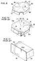
- An air bag device for a driver is installed in a steering wheel of a vehicle, and, as shown in FIG. 10, comprises a retainer 10, an air bag, an inflator for generating gas (neither shown) fixed to the retainer 10 and a cover 12 which covers the air bag in a folded state.
- the inflator When the inflator is actuated, the cover 10 tears along the tear lines 14 and 16, so that flaps are formed. The flaps thus formed by the tear lines pivot open in the directions shown by the arrows 20 about the sides 12a.
- a front opening of the container is covered with a cover (lid) 24, and an inflator (not shown) is mounted on the container 22.
- the cover is shaped generally rectangular. When the inflator is actuated, the cover pivots open about a long side 24a as shown by an arrow 26.
- An object of the present invention is to make less the energy which is absorbed by the cover deformed during the inflator actuation to extend the air bag.
- easily bendable low rigidity line-shaped portions are provided in the cover to make the cover bend along these low rigidity portions when it pivots.
- the cover of the present invention covers the folded air bag of the air bag device and pivots open about one of its sides when the air bag inflates.
- the cover is characterized in that it comprises line-shaped low rigidity portions to allow the cover to bend when the cover pivots open.
- the easily bendable line is oriented in a direction which intersects with an axis about which the cover pivots when it pivots open.
- the cover bends along its low rigidity lines as well as the cover pivots open about its axis of rotation. Accordingly, the stress applied to the cover by the air bag is concentrated in the low rigidity lines, whereby the cover is easily bent along the low rigidity lines even the stress applied to the cover is small. As a result, less energy is consumed in deforming the cover.
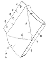
- FIGS. 1 to 4 show a first embodiment of the invention.
- the cover 30 is for an air bag device for a passenger, and is roughly rectangular in shape.
- An ear portion 32 by which the cover 30 is fixed to the container (not shown in FIGS. 1 to 4) is formed along one of the long sides of the cover 30 as an integral part of the cover.
- Bolt holes 34 are provided in this ear portion 32 for fixing the cover 30 to the container.
- the cover 30 is made entirely of synthetic resin, and, as shown in FIG. 2, is provided with a low rigidity portion 36, consisting of a groove formed in the back side of the cover 30.
- the low rigidity portion 36 runs from both ends of the ear portion 32 to a mid-point on the side opposite the ear portion 32.
- the low rigidity portion 36 divides the cover up into three triangular areas: a first area 38, a second area 40 and a third area 42.
- Each of the areas 38, 40 and 42 is provided with a high rigidity portion 44, 46, 48 consisting of a rib.
- the air bag is positioned in the downward side of the cover 30 in FIG. 1.
- the inflator (not shown) is actuated to extend the air bag so that the cover 30 is pushed
- the cover 30 bends along the low rigidity portion 36 whereby the first and second areas 38 and 40 are pushed up, as shown in FIG. 3.
- the cover 30 bends along the ear portion 32, as shown in FIG. 4, the whole cover 30 pivots out into a cabin of a vehicle, and the air bag is allowed to extend into the cabin.
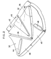
- FIG. 5 is a perspective view of the cover 50 according to another preferred embodiment of the invention
- FIG. 6 is a view illustrating the deformation of the cover 50.
- the cover 50 has a low rigidity portion 54 consisting of a deep groove.
- the groove runs across the cover toward the ear portion 52 from a mid-point of a side opposite the ear portion 52.
- a leading end of the low rigidity portion 56 finishes at half way of the cover 50.
- Another low rigidity portion 56 consisting of a shallow groove, run sideward from the leading end of the low rigidity portion 54.
- the groove runs at a slant across the cover with respect to a longitudinal direction of the ear portion 52.
- a reference numeral 58 denotes a bolt hole provided in the ear portion 52.
- the cover 50 When the air bag (not shown) is extended by the inflator, the cover 50 bends into a V-shape along the low rigidity portion 54, and bends into an inverted V-shape along the low rigidity portion 56, as shown in FIG. 6.
- the pushing effort exerted on the cover 50 by the air bag is concentrated on the low rigidity portions 54 and 56. Accordingly, the cover 50 bends readily along these low rigidity portions, and relatively little energy is consumed in deforming the cover 50.
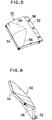
- FIG. 7 is a perspective view of a cover 60 of an air bag device for a passenger according to still another preferred embodiment of the invention
- FIG. 8 is a view illustrating the deformation of the cover 60.
- the cover 60 also has an ear portion 64 provided with bolt holes 62.
- the cover 60 has a low rigidity portions 66, 68 and 69.
- the portion 66 runs across the cover 60 toward the ear portion 64 from a mid-point 66S on the side opposite the ear portion 64.
- the low rigidity portions 68 run from the end point 66E of the low rigidity portion 66, in two directions to both sides of the cover 60.
- the portion 68 runs at a slant with respect to a longitudinal direction of the ear portion 64.
- the low rigidity portions 69 run in two directions to both sides of the cover 60.
- the portion 69 runs from a mid-point 66M of the portion 66 toward the sides.
- the cover 60 bends along the low rigidity portions 68 and 69 into an inverted V-shape, as shown in FIG. 8.
- the cover bends into a V-shape along the low rigidity portion 66 between points 66S and 66M.
- the cover 60 also bends into a inverted V-shape between the points 66M and 66E.
- the pushing effort exerted on the cover 60 by the air bag is concentrated on the low rigidity portions 66, 68 and 69, so that the cover 60 bends readily along the low rigidity portions. Relatively little energy is consumed in deforming the cover 60.
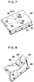
- the invention can also be applied to a cover 70 of an air bag device for a driver.
- the cover 70 has tear lines 72, 74 along both sides thereof and another tear line 76 running between the mid-points of the tear lines 72 and 74.
- Two flap portions 80 and 82 separated by the tear line 76 are each provided with a low rigidity portion 84, 86 each consisting of grooves respectively.
- the tear lines 76, 72 and 74 tear, so that the flap portions 80 and 82 open out into a cabin of a vehicle.
- areas between the tear line 76 and portions 84, 86 are opened first with bending the areas along portions 84, 86. Thereafter, the whole flap portions 80 and 82 pivot open respectively.
- the pushing effort exerted on the cover 70 by the air bag is concentrated on the low rigidity portions 84 and 86, so that the cover bends readily along the low rigidity portions 84, 86. Accordingly, relatively little energy is consumed in deforming the cover.
Applications Claiming Priority (2)
| Application Number | Priority Date | Filing Date | Title |
|---|---|---|---|
| JP4292924A JPH06144141A (ja) | 1992-10-30 | 1992-10-30 | エアバッグ装置のカバー |
| JP292924/92 | 1992-10-30 |
Publications (2)
| Publication Number | Publication Date |
|---|---|
| EP0595512A2 true EP0595512A2 (de) | 1994-05-04 |
| EP0595512A3 EP0595512A3 (de) | 1994-10-05 |
Family
ID=17788173
Family Applications (1)
| Application Number | Title | Priority Date | Filing Date |
|---|---|---|---|
| EP9393308244A Withdrawn EP0595512A3 (de) | 1992-10-30 | 1993-10-15 | Abdeckung für eine Air-bag-Vorrichtung. |
Country Status (4)
| Country | Link |
|---|---|
| EP (1) | EP0595512A3 (de) |
| JP (1) | JPH06144141A (de) |
| KR (1) | KR940008967A (de) |
| CN (1) | CN1088880A (de) |
Cited By (1)
| Publication number | Priority date | Publication date | Assignee | Title |
|---|---|---|---|---|
| EP1050436A1 (de) * | 1999-05-07 | 2000-11-08 | Johnson Controls - Roth | Einrichtung zur Montage und Befestigung eines Verkleidungs- oder Abdeckelements |
Families Citing this family (4)
| Publication number | Priority date | Publication date | Assignee | Title |
|---|---|---|---|---|
| JP2877035B2 (ja) * | 1995-06-15 | 1999-03-31 | 株式会社デンソー | 内燃機関用スパークプラグ |
| JPH09285506A (ja) * | 1996-04-19 | 1997-11-04 | Atom Medical Kk | 保育器 |
| JP3913999B2 (ja) * | 2001-03-02 | 2007-05-09 | カルソニックカンセイ株式会社 | 車両用エアバッグ装置 |
| JP5456288B2 (ja) * | 2008-09-08 | 2014-03-26 | オートリブ ディベロップメント エービー | エアバッグドア構造 |
Citations (4)
| Publication number | Priority date | Publication date | Assignee | Title |
|---|---|---|---|---|
| DE2320272A1 (de) * | 1972-05-19 | 1973-11-29 | Gen Motors Corp | Fahrgast-auffanganlage fuer kraftfahrzeuge |
| US3930664A (en) * | 1972-05-19 | 1976-01-06 | General Motors Corporation | Occupant restraint system |
| DE2536933A1 (de) * | 1974-08-19 | 1976-03-25 | Kohkoku Chemical Ind Co | Sicherheitsvorrichtung und verfahren zu ihrer herstellung |
| DE3116538A1 (de) * | 1981-04-25 | 1982-11-11 | Petri Ag, 8750 Aschaffenburg | Gehaeuse fuer gassack-aufprall-schutzeinrichtungen |
-
1992
- 1992-10-30 JP JP4292924A patent/JPH06144141A/ja active Pending
-
1993
- 1993-06-05 KR KR1019930010162A patent/KR940008967A/ko not_active Application Discontinuation
- 1993-10-15 EP EP9393308244A patent/EP0595512A3/de not_active Withdrawn
- 1993-10-25 CN CN93119423A patent/CN1088880A/zh active Pending
Patent Citations (4)
| Publication number | Priority date | Publication date | Assignee | Title |
|---|---|---|---|---|
| DE2320272A1 (de) * | 1972-05-19 | 1973-11-29 | Gen Motors Corp | Fahrgast-auffanganlage fuer kraftfahrzeuge |
| US3930664A (en) * | 1972-05-19 | 1976-01-06 | General Motors Corporation | Occupant restraint system |
| DE2536933A1 (de) * | 1974-08-19 | 1976-03-25 | Kohkoku Chemical Ind Co | Sicherheitsvorrichtung und verfahren zu ihrer herstellung |
| DE3116538A1 (de) * | 1981-04-25 | 1982-11-11 | Petri Ag, 8750 Aschaffenburg | Gehaeuse fuer gassack-aufprall-schutzeinrichtungen |
Cited By (2)
| Publication number | Priority date | Publication date | Assignee | Title |
|---|---|---|---|---|
| EP1050436A1 (de) * | 1999-05-07 | 2000-11-08 | Johnson Controls - Roth | Einrichtung zur Montage und Befestigung eines Verkleidungs- oder Abdeckelements |
| FR2793201A1 (fr) * | 1999-05-07 | 2000-11-10 | Johnson Controls Roth | Dispositif pour le montage et la fixation d'un element de garniture ou de recouvrement |
Also Published As
| Publication number | Publication date |
|---|---|
| EP0595512A3 (de) | 1994-10-05 |
| KR940008967A (ko) | 1994-05-16 |
| CN1088880A (zh) | 1994-07-06 |
| JPH06144141A (ja) | 1994-05-24 |
Similar Documents
| Publication | Publication Date | Title |
|---|---|---|
| US5060972A (en) | Air bag system | |
| EP0904992B1 (de) | Plazierungsanordnung für einen kopfschützenden Luftsack | |
| US5297813A (en) | Air bag device having a connecting arrangement to facilitate assembly | |
| US5342090A (en) | Passenger air bag module with means for retaining an air bag deployment door to a housing | |
| US5378014A (en) | Dual door arrangement for air bag deployment | |
| EP1211146A1 (de) | Luftsackvorrichtung | |
| US5350191A (en) | Lid of an air bag device for a passenger | |
| JPH10273005A (ja) | 車両用エアバッグ装置 | |
| KR20220026939A (ko) | 차량용 운전석 에어백 장치 | |
| EP0595512A2 (de) | Abdeckung für eine Air-bag-Vorrichtung | |
| US5427409A (en) | Folded airbag cover panel | |
| JPH05262198A (ja) | 助手席用エアバッグ装置のリッド | |
| EP0770522A1 (de) | Vorrichtung zum Erleichtern des Öffnens eines integralen Entfaltungsdeckels in dem Verkleidungsteil eines Luftsacksystems | |
| JPH05270339A (ja) | エアバッグ装置のモジュールカバー | |
| US6168230B1 (en) | Defroster duct installation structure | |
| US5358271A (en) | Structure for attaching a module cover of an air bag device for a passenger | |
| JPH03279053A (ja) | 自動車のエアバッグ装置 | |
| JP3926553B2 (ja) | 車両用エアバッグリッド部構造 | |
| JP2007508992A (ja) | 自動車エアバッグモジュールを収容するためのハウジング | |
| JP2564846Y2 (ja) | 自動車のエアバッグ構造 | |
| JP3144139B2 (ja) | エアバッグの開口リッド構造 | |
| JPH115506A (ja) | エアバッグドア部を有する車両用内装部材 | |
| JPS6232925Y2 (de) | ||
| KR0133115Y1 (ko) | 자동차의 승객용 에어백 구조 | |
| JP3087803B2 (ja) | エアバック用カバー |
Legal Events
| Date | Code | Title | Description |
|---|---|---|---|
| PUAI | Public reference made under article 153(3) epc to a published international application that has entered the european phase |
Free format text: ORIGINAL CODE: 0009012 |
|
| AK | Designated contracting states |
Kind code of ref document: A2 Designated state(s): DE FR GB SE |
|
| PUAL | Search report despatched |
Free format text: ORIGINAL CODE: 0009013 |
|
| AK | Designated contracting states |
Kind code of ref document: A3 Designated state(s): DE FR GB SE |
|
| STAA | Information on the status of an ep patent application or granted ep patent |
Free format text: STATUS: THE APPLICATION IS DEEMED TO BE WITHDRAWN |
|
| 18D | Application deemed to be withdrawn |
Effective date: 19950406 |