EP0592902B1 - Dispositif optique avec une transmission lumineuse variable - Google Patents
Dispositif optique avec une transmission lumineuse variable Download PDFInfo
- Publication number
- EP0592902B1 EP0592902B1 EP93115937A EP93115937A EP0592902B1 EP 0592902 B1 EP0592902 B1 EP 0592902B1 EP 93115937 A EP93115937 A EP 93115937A EP 93115937 A EP93115937 A EP 93115937A EP 0592902 B1 EP0592902 B1 EP 0592902B1
- Authority
- EP
- European Patent Office
- Prior art keywords
- end section
- optical
- section
- mantle
- movable
- Prior art date
- Legal status (The legal status is an assumption and is not a legal conclusion. Google has not performed a legal analysis and makes no representation as to the accuracy of the status listed.)
- Expired - Lifetime
Links
Images


Classifications
-
- G—PHYSICS
- G02—OPTICS
- G02B—OPTICAL ELEMENTS, SYSTEMS OR APPARATUS
- G02B6/00—Light guides; Structural details of arrangements comprising light guides and other optical elements, e.g. couplings
- G02B6/24—Coupling light guides
- G02B6/26—Optical coupling means
- G02B6/28—Optical coupling means having data bus means, i.e. plural waveguides interconnected and providing an inherently bidirectional system by mixing and splitting signals
- G02B6/2804—Optical coupling means having data bus means, i.e. plural waveguides interconnected and providing an inherently bidirectional system by mixing and splitting signals forming multipart couplers without wavelength selective elements, e.g. "T" couplers, star couplers
- G02B6/2817—Optical coupling means having data bus means, i.e. plural waveguides interconnected and providing an inherently bidirectional system by mixing and splitting signals forming multipart couplers without wavelength selective elements, e.g. "T" couplers, star couplers using reflective elements to split or combine optical signals
-
- G—PHYSICS
- G02—OPTICS
- G02B—OPTICAL ELEMENTS, SYSTEMS OR APPARATUS
- G02B6/00—Light guides; Structural details of arrangements comprising light guides and other optical elements, e.g. couplings
- G02B6/24—Coupling light guides
- G02B6/26—Optical coupling means
- G02B6/35—Optical coupling means having switching means
- G02B6/3502—Optical coupling means having switching means involving direct waveguide displacement, e.g. cantilever type waveguide displacement involving waveguide bending, or displacing an interposed waveguide between stationary waveguides
-
- G—PHYSICS
- G02—OPTICS
- G02B—OPTICAL ELEMENTS, SYSTEMS OR APPARATUS
- G02B6/00—Light guides; Structural details of arrangements comprising light guides and other optical elements, e.g. couplings
- G02B6/24—Coupling light guides
- G02B6/26—Optical coupling means
- G02B6/35—Optical coupling means having switching means
- G02B6/351—Optical coupling means having switching means involving stationary waveguides with moving interposed optical elements
- G02B6/3522—Optical coupling means having switching means involving stationary waveguides with moving interposed optical elements the optical element enabling or impairing total internal reflection
-
- G—PHYSICS
- G02—OPTICS
- G02B—OPTICAL ELEMENTS, SYSTEMS OR APPARATUS
- G02B6/00—Light guides; Structural details of arrangements comprising light guides and other optical elements, e.g. couplings
- G02B6/24—Coupling light guides
- G02B6/26—Optical coupling means
- G02B6/35—Optical coupling means having switching means
- G02B6/354—Switching arrangements, i.e. number of input/output ports and interconnection types
- G02B6/3544—2D constellations, i.e. with switching elements and switched beams located in a plane
- G02B6/3546—NxM switch, i.e. a regular array of switches elements of matrix type constellation
-
- G—PHYSICS
- G02—OPTICS
- G02B—OPTICAL ELEMENTS, SYSTEMS OR APPARATUS
- G02B6/00—Light guides; Structural details of arrangements comprising light guides and other optical elements, e.g. couplings
- G02B6/24—Coupling light guides
- G02B6/26—Optical coupling means
- G02B6/35—Optical coupling means having switching means
- G02B6/354—Switching arrangements, i.e. number of input/output ports and interconnection types
- G02B6/3544—2D constellations, i.e. with switching elements and switched beams located in a plane
- G02B6/3548—1xN switch, i.e. one input and a selectable single output of N possible outputs
- G02B6/3552—1x1 switch, e.g. on/off switch
-
- G—PHYSICS
- G02—OPTICS
- G02B—OPTICAL ELEMENTS, SYSTEMS OR APPARATUS
- G02B6/00—Light guides; Structural details of arrangements comprising light guides and other optical elements, e.g. couplings
- G02B6/24—Coupling light guides
- G02B6/26—Optical coupling means
- G02B6/35—Optical coupling means having switching means
- G02B6/3564—Mechanical details of the actuation mechanism associated with the moving element or mounting mechanism details
- G02B6/3568—Mechanical details of the actuation mechanism associated with the moving element or mounting mechanism details characterised by the actuating force
- G02B6/3578—Piezoelectric force
-
- G—PHYSICS
- G02—OPTICS
- G02B—OPTICAL ELEMENTS, SYSTEMS OR APPARATUS
- G02B6/00—Light guides; Structural details of arrangements comprising light guides and other optical elements, e.g. couplings
- G02B6/24—Coupling light guides
- G02B6/36—Mechanical coupling means
- G02B6/38—Mechanical coupling means having fibre to fibre mating means
- G02B6/3807—Dismountable connectors, i.e. comprising plugs
- G02B6/381—Dismountable connectors, i.e. comprising plugs of the ferrule type, e.g. fibre ends embedded in ferrules, connecting a pair of fibres
- G02B6/3818—Dismountable connectors, i.e. comprising plugs of the ferrule type, e.g. fibre ends embedded in ferrules, connecting a pair of fibres of a low-reflection-loss type
- G02B6/3822—Dismountable connectors, i.e. comprising plugs of the ferrule type, e.g. fibre ends embedded in ferrules, connecting a pair of fibres of a low-reflection-loss type with beveled fibre ends
Definitions
- the invention relates to an optical component for influencing the transmission properties of light, with at least two end sections formed by optical waveguides, which consist of a glass fiber and a jacket surrounding the same, wherein at least one end section is movable between two end positions, one end position the two end sections are optically coupled and optically decoupled in the other end position, in which the end sections have inclined surfaces facing one another with an angle of the surface normal to the axis of the glass fibers which exceeds the critical angle of total reflection and in which the travel of the movable end section is considerably smaller than that The diameter of the glass fiber is.
- optical component with a switching function can be found in DE-A-3 644 802.
- optical fiber end sections lying on the same axis are moved radially against one another, so that light can pass from one end section to the other in the coupled state, while in the decoupled state the passage of light is blocked.
- a considerable displacement path must be traveled through, which corresponds practically to the strength of the core zone of the optical waveguides. This shifting path already results in long switching times.
- planar waveguides themselves have comparatively high attenuation values, so that continuity losses of less than 3 dB in an optical switch are unlikely to be realizable.
- the wavelength and polarization dependency and the insufficient crosstalk attenuation are disadvantageous for switching elements in an integrated optical design, in particular for applications in the local network for analog transmission.
- the invention has for its object to develop the optical component described in such a way that it is improved over the known optical components with respect to the transmission loss, the barrier attenuation, the return loss, the crosstalk, the switching times, the manufacturing costs and / or the dimensions and that it is particularly suitable for use in the subscriber access area of telecommunications networks and in this respect comes as close as possible to the requirements for an ideal switch.
- the two opposite end sections are so inclined with respect to the optical axis that there is total reflection.
- the end sections are separated from one another, the supplied light is thus completely reflected. This reflection takes place completely and without loss.
- a small proportion of the electromagnetic field penetrates the optically thinner medium in the form of an exponentially decaying wave.
- Z is the distance from the interface and ⁇ 2 is the wavelength in the optically thinner medium.
- the attenuation of the optical power corresponds to the square of the field amplitude A.
- a value of -55 dB can be calculated for the distance of one wavelength, that is, in the case of light of approximately 1.5 ⁇ m. If thus facing inclined surfaces of the opposite end sections approach each other up to 1.5 ⁇ m, there is practically no coupling of light into the second end section. However, if the approximation continues until there is an optical contact, at least after the Theory - a lossless passage of radiation.
- the manufacturing costs of the optical component which can preferably be used as a switch, are very low.
- complex adaptation measures such as in the case of integrated optical light couplers can be dispensed with.
- the structural dimensions are small.
- the use of the piezoelectric actuator results in good vibration resistance due to the small size required and the possible compact design.
- the most favorable angle of the inclined surface with respect to the optical axis of the optical waveguide can be determined experimentally.
- the surface normal of the inclined surface has an angle to the optical axis that exceeds the critical angle of the total reflection.
- Refractive indices for quartz glass which can be pure or lightly doped, give values between 1.44 and 1.46 for n 1 in the wavelength range from 1.2 to 1.7 ⁇ m, so that the critical angle of total reflection is between 43 ° and 44 ° can be adopted. Accordingly, the angle of the inclined surface can preferably be chosen to be 45 °, so that total reflection is present with a certain safety distance.
- the outer cladding of the optical waveguide is expediently removed in the region of the end sections when the inclined surfaces have been polished. If a quartz glass fiber of 125 microns in diameter is used, the jacket in its longitudinal direction z. B. Be at least about 0.5 mm away, but a distance of 1 mm does not lead to instabilities.
- the piezoelectric actuating element is connected directly to the mutually movable end sections. Temperature influences can be kept as low as possible, and it is also favorable that when using a piezoelectric crystal made of quartz, the thermal expansion coefficients are approximately the same as for optical fibers made of quartz glass.
- the assembly of the control element decides whether there is a passage or a blockage in the de-energized state. If the installation is carried out in abutment of the inclined surfaces, a break contact occurs, while when an intermediate layer is used, the optical component acts like a work contact of a switch. In order to enable deflection symmetrically in both directions, an intermediate layer of 0.75 ⁇ m can also be used, so that a movement arises when moving in one direction around 750 nm and a distance of 1500 nm is created when deflection in the opposite polarity. This possibility of symmetrical deflection for the actuating element is preferred when using the optical component as a modulator. The low installation costs are favorable here, since the system does not require any special distance adjustment.
- the radiation-emitting end section which is referred to here as the first end section
- a third end section which extends transversely away from its end.
- this end section can extend laterally at an angle of 90 °, so that when the optical component is blocked, the radiation totally reflected by the inclined surface of the first end section enters the third end section, which therefore preferably in the optical axis the reflected radiation is attached. Since no or almost no radiation is reflected when the inclined surfaces of the first and second end sections are in contact with one another, a changeover switch can be implemented in this way.
- the third end section is in good optical contact with the glass fiber of the first end section.
- the major part of the jacket is preferably removed at the tapering end of the first end section, whereby according to one embodiment it is even provided that the end of the third end section is concave, so that it surrounds the quartz glass fiber of the first end sections directly on one side.
- any adhesive used should be used in have essentially the same refractive index so that the losses at the transition point are minimal.
- the second end section is preferably movably mounted in the optical component having three end sections and thus forming a changeover switch.
- a fourth end section is also possible to attach a fourth end section to the second end section, the design of which essentially corresponds to the third end section attached to the first end section.
- the use of a second piezoelectric actuating element is advantageous due to the increased mass to be moved. While light power can be passed between the first and the second or the second and the first end section in the optical contact between the inclined surfaces of the end sections, the introduced light power can occur from the first to the third and / or from the second to the fourth end section in the blocked state.
- Fig. 1 shows an embodiment of an optical component according to the invention with a first and a second end section.
- FIG. 2 shows an embodiment of the optical component, a third end section being added to the first end section.
- FIG. 3 shows a modification of the embodiment according to FIG. 2.
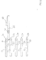
- Fig. 4 shows a further embodiment of an optical component with four end sections.
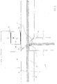
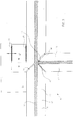
- FIG. 5 shows a further embodiment of an optical component according to the invention, in which switching between a plurality of optical fibers and multiplexing is possible.
- An optical component 10 has an optical waveguide 12 which is divided by a miter cut 14.
- the optical waveguide 12 has a cladding 16 and a core zone or quartz glass fiber 18. Due to the miter cut 14, the optical waveguide 12 is divided into a first end section 20 and a second end section 22, the first end section 20 having a first bevel surface 24 and the second end section being a second bevel surface Have 26, which face each other.
- the cutting angle of the miter cut 14 is approximately 45 °.
- the Inclined surfaces 24 and 26 are each ground or polished in order to achieve a surface with a low roughness depth at least in the area of the quartz glass fiber 18.
- a holding body 28 is provided below the end sections 20 and 22, which has a V-groove at the top. The V-groove serves as a guide element and adjustment aid for the end sections 20 and 22.
- the assembly is carried out so that the inclined surfaces 24 and 26 are at a distance of 2 microns in the rest state.
- the two end sections 20 and 22 are mounted in a protective gas-filled housing.
- the second end section 22 can be moved relative to the first end section 20 to thereby achieve a switching or modulator function.
- a piezoelectric actuating element 30 is designed as a piezoelectric crystal.
- the piezoelectric crystal is fastened to a holding body 32 which bears against the first end section 20 with a contact leg 34.
- the actuating element 30 has two electrodes 36 and 38 lying opposite one another, which preferably bring about a change in the thickness of the piezoelectric actuating element 30.
- the second end section 22 is moved in the radial direction by the change in thickness of the piezoelectric actuating element 30.
- the travel range is so small that you can always work in the lower area of the elastic deformation.
- the holding body 32 is bow-shaped, so that it has, in addition to the contact leg 34, a further contact leg 40 for contacting a spaced area of the second end section 22.
- the sloping surfaces 24 and 26 are flat. A flatness of less than 5 nm can easily be achieved in practice. Thus, it should not pose any problems even on a large industrial scale to ensure a flatness of less than 10 nm, so that the transmission loss can maintain the desired values.
- a housing filled with nitrogen or noble gas as a protective gas is particularly advantageous in order to protect the inclined surfaces 24 and 26 against contamination or chemical changes due to water vapor or other aggressive substances.
- a quartz glass tube can be used as the housing, the electrical leads can be led out at the end. The dimensions of such a quartz glass tube would correspond approximately to those of a conventional fusion coupler.
- the inclined surfaces 24 and 26 could be polished slightly convex.
- the radii of curvature can be considerably larger than is known for optical connectors. It is particularly favorable for the optical component that the moving mass is quite small, as well as that the required displacement is only 1 - 2 ⁇ m. If a diameter of 125 ⁇ m, a density of 2.2 g / cm 3 is assumed for a quartz glass fiber and the quartz glass fiber is moved over a length of 1 mm, the mass to be moved is 30 ⁇ g.
- piezoelectric quartz crystals are known in which gold is used as the electrode material with an electrode area of one square millimeter and a layer thickness of 1 ⁇ m.
- the mass of a gold electrode is 20 ⁇ g. It is therefore of the same order of magnitude as the mass of the optical component to be moved.
- quartz crystals can easily be excited with frequencies up to 150 MHz.
- the oscillation frequency is not significantly reduced by the coupling of the movable end section 22.
- Switching times of up to approximately 10 ns should therefore be possible, so that the optical component can also be used as a modulator for frequencies up to approximately 100 MHz.
- the jacket 16 is at least partially removed in the range of motion. As a result, the actuating element 30 can be attached closer to the core region 18 and the mass to be moved is reduced.
- FIG. 2 A further embodiment of the optical component 10 can be seen in FIG. 2.
- a third end section 42 is provided, which is optically coupled to the first end section 20.
- the jacket 16 is removed at the pointed end of the first end section 20.
- the third end section 42 ends with a flat surface 44. Radiation entering the first end section 20 from the left is reflected on the first inclined surface 24 in the blocked state of the optical component 10. It then enters directly into the core area of the third end section 42. A region of the circumferential surface 16 remains adjacent to the core zone 18 of the first end section 20. As a result, the radiation losses in the transmission state can be kept low.
- the remaining strength of the Jacket 16 can be, for example, a few micrometers.
- the beam passing through the first end section 20 experiences a slight concentration due to the refractive index distribution, since the refractive index distribution has the effect of a weak cylindrical lens.
- This beam deformation results in small coupling losses for the third end section 42.
- These losses can be reduced by interposing a coupling element 46 with a corresponding refractive index distribution to compensate for the refractive index distribution of the optical waveguide 12.
- the coupling member 46 can either be mounted on the flat surface 44 of the third end section 42 or on the ground surface of the end section 20. While in the transmission state the entire light output from the end section 20 enters the end section 22, almost all of the light output from the end section occurs in the blocked state 20 in the third end section 42.
- the holding body 32 is L-shaped, with care being taken to ensure stable relative support between the first end section 20 and the second end section 22.
- the contact leg 34 is firmly connected to the first end section 20 using a suitable adhesive.
- the holding body 32 consists of quartz glass and connects the end sections 20 and 22 to one another via the two electrodes 36 and 38 of the actuating element 30.
- FIG. 3 A further embodiment of the optical component 10 can be seen in FIG. 3.
- This exemplary embodiment differs from the exemplary embodiment shown in FIG. 2 essentially by the configuration of the third end section 42.
- the casing 16 of the third end section is provided in this exemplary embodiment with a cone, which improves adaptation to the suitably tailored casing serving as a guide surface 16 of the first end section 20 allowed.
- FIG. 4 shows a further embodiment of the optical component 10. Compared to the configuration according to FIG. 3, it has an additional fourth end section 48 and an additional adjusting element 50, the configuration of which corresponds to the adjusting element 30.
- the optical component 10 according to FIG. 4 is symmetrical and allows the realization of a bidirectional switch.
- the fourth end section 48 acts as a further coupling fiber and is designed corresponding to the third end section 42 according to FIG. 3, but it does not come on the first end portion 20, but is attached to the second end portion 22. With this switch, the additional beam path results from the second end section 20 into the fourth end section 48.
- a further end section 42 or 48 has to be moved, which extends to the cross section, it appears sensible to use the further piezoelectric actuating element 50.
- the actuating element 50 is preferably actuated synchronously with the actuating element 30. It therefore allows the provision of doubled actuating forces, which is favorable in view of the increased masses to be moved.
- the end sections 42 and 48 are preferably curved in the further course in order to increase the axial mobility.
- Such optical components can preferably be used as bidirectional switches in the subscriber access area.
- a further piezoelectric actuating element 60 is provided, which acts on the movable end section 22 in a direction essentially perpendicular to the action of the actuating element 30. Only part of the actuating element 60 is shown in FIG. 5. The range of movement of the actuating element 60 is considerably larger than the actuating path of the actuating element 30. Even if, as shown in FIG. 5, the actuating element 60 is shown acting directly on the optical waveguide, it can also act on the fastening area of the actuating element 30.
- the optical waveguides 20 each have inclined surfaces 24 which are essentially parallel to one another, an arc-shaped arrangement also being possible.
Landscapes
- Physics & Mathematics (AREA)
- General Physics & Mathematics (AREA)
- Optics & Photonics (AREA)
- Mechanical Light Control Or Optical Switches (AREA)
- Optical Couplings Of Light Guides (AREA)
- Light Guides In General And Applications Therefor (AREA)
Claims (6)
- Composant optique permettant d'influencer les caractéristiques de transmission de la lumière avec au moins deux tronçons d'extrémité (20, 22) formés par des guides d'ondes lumineuses (12) composés d'une fibre optique (18) et d'une gaine (16) qui enrobe celle-ci, l'un au moins des tronçons d'extrémité est mobile entre deux positions extrêmes, dans l'une des positions extrêmes les deux tronçons d'extrémité (20, 22) sont couplés optiquement et dans l'autre position découplés, dans ladite position (20, 22) la normale aux surfaces obliques (24, 26) des tronçons d'extrémité tournées l'une vers l'autre forme avec l'axe de la fibre optique (18) un angle qui dépasse l'angle limite de réflexion totale et la distance de déplacement du tronçon mobile (20, 22) est nettement inférieure au diamètre de la fibre optique (18), caractérisé par le fait- qu'au moins au niveau d'un des tronçons d'extrémité mobiles (20, 22) et au voisinage de l'extrémité mobile de celui-ci la gaine (16) du guide d'ondes lumineuses (12) est partiellement enlevée et- que le déplacement du tronçon d'extrémité (20, 22) mobile se fait transversalement à l'axe du guide d'ondes lumineuses (12) et est provoqué par un élément de réglage piézo-électrique (30).
- Composant selon la revendication 1 caractérisé par le fait que l'élément de réglage piézo-électrique (30) est de préférence un cristal piézo-électrique en quartz.
- Composant selon la revendication 1 caractérisé par le fait que l'élément de réglage piézo-électrique (30) est de préférence une céramique piézo-électrique.
- Composant selon les revendications 1 et 3, caractérisé par le fait qu'au voisinage de l'extrémité conique en pointe d'un tronçon d'extrémité (20) est ajouté sur une surface principalement parallèle à l'axe du premier et du deuxième tronçon d'extrémité (20, 22) et formée par l'enlèvement de la gaine (16), un troisième tronçon d'extrémité (42) dont la gaine (16) est partiellement enlevée, dans lequel troisième tronçon d'extrémité (42) on peut coupler le rayon totalement réfléchi par la surface oblique (24), lorsque le premier et le deuxième tronçon d'extrémité (20, 22) sont découplés.
- Composant selon la revendication 4, caractérisé par le fait- que la gaine (16) est enlevée sur une épaisseur de quelques µm et- que la surface d'extrémité du troisième tronçon d'extrémité (42) est adaptée à une surface plane (44) et que le troisième tronçon d'extrémité (42) est une partie d'un guide d'ondes lumineuses (12) qui se présente transversalement et plus particulièrement perpendiculairement à l'axe du premier et du deuxième tronçon d'extrémité (20, 22)
- Composant selon les revendications 4 ou 5, caractérisé par le fait qu'un surface plane est formée sur le deuxième tronçon d'extrémité (22) par enlèvement de la gaine (16) du guide d'ondes lumineuses correspondant (12) sur laquelle est ajouté un quatrième tronçon d'extrémité (48) avec une surface d'extrémité.
Applications Claiming Priority (2)
| Application Number | Priority Date | Filing Date | Title |
|---|---|---|---|
| DE4233489A DE4233489A1 (de) | 1992-10-05 | 1992-10-05 | Optisches Bauelement |
| DE4233489 | 1992-10-05 |
Publications (2)
| Publication Number | Publication Date |
|---|---|
| EP0592902A1 EP0592902A1 (fr) | 1994-04-20 |
| EP0592902B1 true EP0592902B1 (fr) | 1997-12-17 |
Family
ID=6469698
Family Applications (1)
| Application Number | Title | Priority Date | Filing Date |
|---|---|---|---|
| EP93115937A Expired - Lifetime EP0592902B1 (fr) | 1992-10-05 | 1993-10-02 | Dispositif optique avec une transmission lumineuse variable |
Country Status (4)
| Country | Link |
|---|---|
| US (1) | US5390266A (fr) |
| EP (1) | EP0592902B1 (fr) |
| JP (1) | JPH06202010A (fr) |
| DE (2) | DE4233489A1 (fr) |
Families Citing this family (34)
| Publication number | Priority date | Publication date | Assignee | Title |
|---|---|---|---|---|
| JPH07104146A (ja) * | 1993-10-01 | 1995-04-21 | Ngk Insulators Ltd | 光部品の製造方法 |
| JPH07104148A (ja) * | 1993-10-01 | 1995-04-21 | Nippon Hoso Kyokai <Nhk> | 光部品 |
| DE19934184A1 (de) | 1999-07-21 | 2001-01-25 | Siemens Ag | Optische Kopplungseinrichtung |
| DE19934183A1 (de) * | 1999-07-21 | 2001-01-25 | Siemens Ag | Optische Kopplungseinrichtung |
| US6866426B1 (en) | 2000-04-07 | 2005-03-15 | Shipley Company, L.L.C. | Open face optical fiber array for coupling to integrated optic waveguides and optoelectronic submounts |
| US6842552B1 (en) | 2000-04-13 | 2005-01-11 | Shipley Company, L.L.C. | Optical waveguide switch |
| US6798933B2 (en) * | 2000-04-14 | 2004-09-28 | Shipley Company, L.L.C. | Fiber optic array switch |
| US6832016B2 (en) * | 2000-04-13 | 2004-12-14 | Shipley Company, L.L.C. | Fiber array switch having micromachined front face with roller balls |
| US6826324B2 (en) * | 2000-04-13 | 2004-11-30 | Shipley Company, L.L.C. | Optical waveguide switch |
| US6633691B2 (en) * | 2000-05-02 | 2003-10-14 | Shipley Company, L.L.C. | Optical waveguide switch having stepped waveguide holding member |
| US6748131B2 (en) * | 2000-05-19 | 2004-06-08 | Shipley Company, L.L.C. | Optical waveguide devices and methods of fabricating the same |
| US6870981B2 (en) | 2000-08-24 | 2005-03-22 | Shipley Company, L.L.C. | Optical switch and method for making |
| US6853764B2 (en) * | 2000-08-28 | 2005-02-08 | Shipley Company, L.L.C. | Optical switch assembly and method for making |
| US6519382B1 (en) * | 2000-09-11 | 2003-02-11 | Optical Switch Corporation | Frustrated total internal reflection switch using waveguides and method of operation |
| EP1189093A3 (fr) * | 2000-09-14 | 2003-01-02 | Seiko Instruments Inc. | Commutateur optique et procédé de commande associé |
| US6810162B2 (en) * | 2000-12-20 | 2004-10-26 | Shipley Company, L.L.C. | Optical switch assembly with flex plate and method for making |
| US6672773B1 (en) * | 2000-12-29 | 2004-01-06 | Amkor Technology, Inc. | Optical fiber having tapered end and optical connector with reciprocal opening |
| DE10129923C1 (de) * | 2001-06-21 | 2003-02-27 | Inst Mikrotechnik Mainz Gmbh | Optische Schalteinrichtung |
| US6856735B2 (en) * | 2001-11-06 | 2005-02-15 | Chromux Technologies, Inc. | Tap couplers for fiber optic arrays |
| JP2005509190A (ja) * | 2001-11-08 | 2005-04-07 | ローム・アンド・ハース・エレクトロニック・マテリアルズ,エル.エル.シー. | 光ファイバー終端装置 |
| EP1326107A3 (fr) | 2002-01-04 | 2004-03-10 | JDS Uniphase Corporation | Coupleur optique athermique |
| DE10201127C2 (de) * | 2002-01-09 | 2003-11-20 | Infineon Technologies Ag | Anordnung zum Ein- und/oder Auskoppeln optischer Signale mindestens eines optischen Datenkanals in bzw. aus einem Lichtwellenleiter |
| JP2003308714A (ja) * | 2002-04-17 | 2003-10-31 | Fuji Photo Film Co Ltd | 導光フィルム |
| US6898342B2 (en) * | 2002-08-08 | 2005-05-24 | Intel Corporation | Fiber-aligning optical switch |
| US6829413B2 (en) * | 2002-12-02 | 2004-12-07 | International Business Machines Corporation | Ferrule-less optical fiber apparatus for optical backplane connector systems |
| GB2387447B (en) * | 2003-01-20 | 2004-04-28 | Polatis Ltd | Optical connector with total internal reflection surface |
| JP2005195651A (ja) * | 2003-12-26 | 2005-07-21 | Internatl Business Mach Corp <Ibm> | 光接続基板、光伝送システム、及び製造方法 |
| US20080131048A1 (en) * | 2004-08-24 | 2008-06-05 | Auckland Uniservices Limited | Optical Fibre Switch |
| US20070122087A1 (en) | 2005-11-30 | 2007-05-31 | Finisar Corporation | Optical bus |
| CN102272647A (zh) * | 2008-10-31 | 2011-12-07 | 惠普开发有限公司 | 光学互连组件 |
| US8195016B2 (en) * | 2009-11-02 | 2012-06-05 | Harris Corporation | Optical fiber switch including an index matching elastomeric solid layer and related methods |
| US8175426B2 (en) * | 2009-11-02 | 2012-05-08 | Harris Corporation | Optical fiber switch including an index matching elastomeric solid layer providing core and cladding index of refraction matching and related methods |
| US8938148B2 (en) * | 2012-02-16 | 2015-01-20 | Cisco Technology, Inc. | Variable optical attenuator |
| GB2563929A (en) * | 2017-06-30 | 2019-01-02 | Oclaro Tech Ltd | Spatial filter |
Family Cites Families (23)
| Publication number | Priority date | Publication date | Assignee | Title |
|---|---|---|---|---|
| US3338656A (en) * | 1963-12-12 | 1967-08-29 | Barnes Eng Co | Frustrated internal reflection modulator and a method of making the same |
| DE2737499C3 (de) * | 1977-08-19 | 1981-10-22 | Max-Planck-Gesellschaft zur Förderung der Wissenschaften e.V., 3400 Göttingen | Faseroptisches Schaltungselement |
| GB1594336A (en) * | 1977-12-20 | 1981-07-30 | Plessey Co Ltd | Opitcal apparatus for switching or variably coupling light between a plurality of optical fibre light guides |
| DE2803489A1 (de) * | 1978-01-27 | 1979-08-02 | Strobel Christian | Optischer schnellverschluss |
| DE2840493A1 (de) * | 1978-09-18 | 1980-03-27 | Siemens Ag | Frequenzselektives optisches lichtverteilerelement und verfahren zu seiner herstellung |
| DE2842535A1 (de) * | 1978-09-29 | 1980-05-29 | Siemens Ag | Abzweigelement |
| DE2851646A1 (de) * | 1978-11-29 | 1980-07-17 | Siemens Ag | Koppelelement zum auskoppeln eines lichtanteils aus einem optischen wellenleiter und wiedereinkoppeln desselben in einen abzweigenden optischen wellenleiter |
| DE2851654A1 (de) * | 1978-11-29 | 1980-06-26 | Siemens Ag | Koppelelement zum auskoppeln eines lichtanteils aus einem optischen wellenleiter und wiedereinkoppeln desselben in einen abzweigenden optischen wellenleiter sowie verfahren zur herstellung des elements |
| DE2921035C2 (de) * | 1979-05-23 | 1984-11-22 | Siemens AG, 1000 Berlin und 8000 München | Optisches Verzweigerelement |
| US4456329A (en) * | 1979-10-12 | 1984-06-26 | Westinghouse Electric Corp. | Optical device having multiple wavelength dependent optical paths |
| US4303302A (en) * | 1979-10-30 | 1981-12-01 | Gte Laboratories Incorporated | Piezoelectric optical switch |
| DE3138968A1 (de) * | 1981-09-30 | 1983-04-14 | Siemens AG, 1000 Berlin und 8000 München | Optische steuervorrichtung zum steuern der in einem optischen wellenleiter gefuehrten strahlung, insbesondere optischer schalter |
| DE3206919A1 (de) * | 1982-02-26 | 1983-09-15 | Philips Patentverwaltung Gmbh, 2000 Hamburg | Vorrichtung zum optischen trennen und verbinden von lichtleitern |
| JPS60129723A (ja) * | 1983-12-16 | 1985-07-11 | Canon Inc | 光シヤツタ−およびシヤツタ−アレイ装置 |
| US4725115A (en) * | 1985-08-05 | 1988-02-16 | Gould Inc. | Multi-mode, optical fiber laser coupler |
| DE3644802A1 (de) * | 1986-12-31 | 1988-07-14 | Schmitt Hans Juergen | Elektrisch-steuerbarer glasfaser-schalter |
| DE3716836A1 (de) * | 1987-05-20 | 1988-12-01 | Telefonbau & Normalzeit Gmbh | Optischer schalter |
| JPS6465506A (en) * | 1987-09-04 | 1989-03-10 | Seiko Instr & Electronics | Optical attenuator |
| FR2670909B1 (fr) * | 1990-12-21 | 1994-02-11 | Thomson Csf | Dispositif de connexion optique et appareil de traitement de donnees muni de moyens de transmission optique. |
| DE4101791C1 (fr) * | 1991-01-23 | 1991-12-05 | Ant Nachrichtentechnik Gmbh, 7150 Backnang, De | |
| US5129022A (en) * | 1991-02-04 | 1992-07-07 | Eastman Kodak Company | Method and apparatus for providing reference signals from points along an optical fiber transmission path |
| US5136681A (en) * | 1991-07-09 | 1992-08-04 | Seikoh Giken Co., Ltd. | Optical powder attenuator of variable attenuation type |
| US5253312A (en) * | 1992-06-26 | 1993-10-12 | Cytocare, Inc. | Optical fiber tip for use in a laser delivery system and a method for forming same |
-
1992
- 1992-10-05 DE DE4233489A patent/DE4233489A1/de not_active Withdrawn
-
1993
- 1993-10-02 EP EP93115937A patent/EP0592902B1/fr not_active Expired - Lifetime
- 1993-10-02 DE DE59307848T patent/DE59307848D1/de not_active Expired - Fee Related
- 1993-10-04 US US08/133,731 patent/US5390266A/en not_active Expired - Fee Related
- 1993-10-05 JP JP5249492A patent/JPH06202010A/ja active Pending
Also Published As
| Publication number | Publication date |
|---|---|
| DE59307848D1 (de) | 1998-01-29 |
| US5390266A (en) | 1995-02-14 |
| JPH06202010A (ja) | 1994-07-22 |
| EP0592902A1 (fr) | 1994-04-20 |
| DE4233489A1 (de) | 1994-04-07 |
Similar Documents
| Publication | Publication Date | Title |
|---|---|---|
| EP0592902B1 (fr) | Dispositif optique avec une transmission lumineuse variable | |
| DE69617294T2 (de) | Zweidimensionale Segmentierung eines integrierten Wellenleiters zur Modenanpassung an einer Faser | |
| EP1062537B1 (fr) | Commutateur optique et systeme de commutation modulaire constitue d'elements de commutation optique | |
| DE2851667C2 (fr) | ||
| DE3689605T2 (de) | Geräte mit optischen wellenleitern und mit niedrigen verlusten. | |
| EP0495202B1 (fr) | Dispositif pour changer une onde optique avec un petit diamètre du mode en une onde avec un diamètre plus grand | |
| DE3688607T2 (de) | Teilerstruktur, diese Strukturen verwendendes optisches Schaltelement und diese Schaltelemente verwendende optische Schaltmatrix. | |
| DE3036618A1 (de) | Steuerelement zum steuern einer lichtuebertragung zwischen lichtwellenleitern | |
| EP0275068B1 (fr) | Arrangement optique pour transformer sans feedback la radiation polarisée divergente émise par un laser semi-conducteur en une radiation convergente | |
| EP0968454B1 (fr) | Disjoncteur optique a coupure multiple | |
| EP0259933B1 (fr) | Dispositif de commande de polarisation optique avec structure à guide d'ondes | |
| EP0589902B1 (fr) | Circuit optique integre | |
| EP0315270A2 (fr) | Elément optique à portes multiples avec un modulateur acousto-optique | |
| EP1166474B1 (fr) | Procede permettant, au moyen de cristaux photoniques, de compenser la dispersion de signaux optiques de differentes longueurs d'onde transmis ensemble | |
| EP1203252B1 (fr) | Dispositif de couplage optique | |
| DE3929453C1 (en) | Fibre-Fabry-Perot interferometer - has slot in substrate enabling opposite regions to be moved w.r.t. V=shaped groove for optical fibres | |
| EP1236067B1 (fr) | Dispositif optique de couplage | |
| EP1200866B1 (fr) | Dispositif de couplage optique | |
| DE60311984T2 (de) | Optische filtrierungseinrichtung | |
| EP0194325B1 (fr) | Transition non-réfléchissante entre des fibres optiques | |
| EP0226652B1 (fr) | Capteur | |
| EP1210636B1 (fr) | Dispositif de couplage optique | |
| DE3606682C1 (en) | Optical fibre arrangement for microoptical grating multiplexers and demultiplexers | |
| DE4106201C2 (de) | Nichtlineares, planares optisches Bauelement | |
| DE68903767T2 (de) | Faseroptischer schalter. |
Legal Events
| Date | Code | Title | Description |
|---|---|---|---|
| PUAI | Public reference made under article 153(3) epc to a published international application that has entered the european phase |
Free format text: ORIGINAL CODE: 0009012 |
|
| AK | Designated contracting states |
Kind code of ref document: A1 Designated state(s): DE FR GB IT SE |
|
| 17P | Request for examination filed |
Effective date: 19941229 |
|
| 17Q | First examination report despatched |
Effective date: 19950213 |
|
| RAP1 | Party data changed (applicant data changed or rights of an application transferred) |
Owner name: KE KOMMUNIKATIONS-ELEKTRONIK GMBH & CO |
|
| GRAG | Despatch of communication of intention to grant |
Free format text: ORIGINAL CODE: EPIDOS AGRA |
|
| GRAG | Despatch of communication of intention to grant |
Free format text: ORIGINAL CODE: EPIDOS AGRA |
|
| GRAH | Despatch of communication of intention to grant a patent |
Free format text: ORIGINAL CODE: EPIDOS IGRA |
|
| GRAH | Despatch of communication of intention to grant a patent |
Free format text: ORIGINAL CODE: EPIDOS IGRA |
|
| RAP1 | Party data changed (applicant data changed or rights of an application transferred) |
Owner name: ALCATEL ALSTHOM COMPAGNIE GENERALE D'ELECTRICITE |
|
| GRAA | (expected) grant |
Free format text: ORIGINAL CODE: 0009210 |
|
| AK | Designated contracting states |
Kind code of ref document: B1 Designated state(s): DE FR GB IT SE |
|
| PG25 | Lapsed in a contracting state [announced via postgrant information from national office to epo] |
Ref country code: IT Free format text: LAPSE BECAUSE OF FAILURE TO SUBMIT A TRANSLATION OF THE DESCRIPTION OR TO PAY THE FEE WITHIN THE PRE;WARNING: LAPSES OF ITALIAN PATENTS WITH EFFECTIVE DATE BEFORE 2007 MAY HAVE OCCURRED AT ANY TIME BEFORE 2007. THE CORRECT EFFECTIVE DATE MAY BE DIFFERENT FROM THE ONE RECORDED.SCRIBED TIME-LIMIT Effective date: 19971217 Ref country code: GB Free format text: LAPSE BECAUSE OF FAILURE TO SUBMIT A TRANSLATION OF THE DESCRIPTION OR TO PAY THE FEE WITHIN THE PRESCRIBED TIME-LIMIT Effective date: 19971217 Ref country code: FR Free format text: LAPSE BECAUSE OF FAILURE TO SUBMIT A TRANSLATION OF THE DESCRIPTION OR TO PAY THE FEE WITHIN THE PRESCRIBED TIME-LIMIT Effective date: 19971217 |
|
| REF | Corresponds to: |
Ref document number: 59307848 Country of ref document: DE Date of ref document: 19980129 |
|
| PG25 | Lapsed in a contracting state [announced via postgrant information from national office to epo] |
Ref country code: SE Free format text: LAPSE BECAUSE OF FAILURE TO SUBMIT A TRANSLATION OF THE DESCRIPTION OR TO PAY THE FEE WITHIN THE PRESCRIBED TIME-LIMIT Effective date: 19980317 |
|
| EN | Fr: translation not filed | ||
| GBV | Gb: ep patent (uk) treated as always having been void in accordance with gb section 77(7)/1977 [no translation filed] |
Effective date: 19971217 |
|
| PLBE | No opposition filed within time limit |
Free format text: ORIGINAL CODE: 0009261 |
|
| STAA | Information on the status of an ep patent application or granted ep patent |
Free format text: STATUS: NO OPPOSITION FILED WITHIN TIME LIMIT |
|
| 26N | No opposition filed | ||
| PGFP | Annual fee paid to national office [announced via postgrant information from national office to epo] |
Ref country code: DE Payment date: 20011005 Year of fee payment: 9 |
|
| PG25 | Lapsed in a contracting state [announced via postgrant information from national office to epo] |
Ref country code: DE Free format text: LAPSE BECAUSE OF NON-PAYMENT OF DUE FEES Effective date: 20030501 |