EP0592879B1 - Gassack-Baugruppe für ein Rückhaltesystem in Fahrzeugen - Google Patents
Gassack-Baugruppe für ein Rückhaltesystem in Fahrzeugen Download PDFInfo
- Publication number
- EP0592879B1 EP0592879B1 EP93115797A EP93115797A EP0592879B1 EP 0592879 B1 EP0592879 B1 EP 0592879B1 EP 93115797 A EP93115797 A EP 93115797A EP 93115797 A EP93115797 A EP 93115797A EP 0592879 B1 EP0592879 B1 EP 0592879B1
- Authority
- EP
- European Patent Office
- Prior art keywords
- relief opening
- gas bag
- bag assembly
- housing
- assembly according
- Prior art date
- Legal status (The legal status is an assumption and is not a legal conclusion. Google has not performed a legal analysis and makes no representation as to the accuracy of the status listed.)
- Expired - Lifetime
Links
- 230000000452 restraining effect Effects 0.000 claims 1
- 238000010276 construction Methods 0.000 description 2
- 230000001419 dependent effect Effects 0.000 description 1
- 239000000126 substance Substances 0.000 description 1
Images


Classifications
-
- B—PERFORMING OPERATIONS; TRANSPORTING
- B60—VEHICLES IN GENERAL
- B60R—VEHICLES, VEHICLE FITTINGS, OR VEHICLE PARTS, NOT OTHERWISE PROVIDED FOR
- B60R21/00—Arrangements or fittings on vehicles for protecting or preventing injuries to occupants or pedestrians in case of accidents or other traffic risks
- B60R21/02—Occupant safety arrangements or fittings, e.g. crash pads
- B60R21/16—Inflatable occupant restraints or confinements designed to inflate upon impact or impending impact, e.g. air bags
- B60R21/26—Inflatable occupant restraints or confinements designed to inflate upon impact or impending impact, e.g. air bags characterised by the inflation fluid source or means to control inflation fluid flow
- B60R21/276—Inflatable occupant restraints or confinements designed to inflate upon impact or impending impact, e.g. air bags characterised by the inflation fluid source or means to control inflation fluid flow with means to vent the inflation fluid source, e.g. in case of overpressure
-
- B—PERFORMING OPERATIONS; TRANSPORTING
- B60—VEHICLES IN GENERAL
- B60R—VEHICLES, VEHICLE FITTINGS, OR VEHICLE PARTS, NOT OTHERWISE PROVIDED FOR
- B60R21/00—Arrangements or fittings on vehicles for protecting or preventing injuries to occupants or pedestrians in case of accidents or other traffic risks
- B60R21/02—Occupant safety arrangements or fittings, e.g. crash pads
- B60R21/16—Inflatable occupant restraints or confinements designed to inflate upon impact or impending impact, e.g. air bags
- B60R21/26—Inflatable occupant restraints or confinements designed to inflate upon impact or impending impact, e.g. air bags characterised by the inflation fluid source or means to control inflation fluid flow
- B60R21/276—Inflatable occupant restraints or confinements designed to inflate upon impact or impending impact, e.g. air bags characterised by the inflation fluid source or means to control inflation fluid flow with means to vent the inflation fluid source, e.g. in case of overpressure
- B60R2021/2765—Inflatable occupant restraints or confinements designed to inflate upon impact or impending impact, e.g. air bags characterised by the inflation fluid source or means to control inflation fluid flow with means to vent the inflation fluid source, e.g. in case of overpressure comprising means to control the venting
Definitions
- the invention relates to an airbag assembly for a restraint system in vehicles, with a housing and at least one pyrotechnic gas generator arranged therein, wherein at least one relief opening is arranged in the wall of the housing, which can be closed by a valve element, this valve element by a a temperature change responsive control element is movable, which closes the relief opening or the relief openings at lower ambient temperatures and releases at higher ambient temperatures.
- Such an airbag assembly is known from JP-A-01 229 739.
- the purpose of the relief opening is to allow a portion of the gas generated by the gas generator to escape from the gas bag assembly above a certain ambient temperature.
- the background to such a construction can be seen in the fact that restraint systems in vehicles have to be functional within a wide temperature range from approximately -35 ° C. to + 85 ° C. Due to the properties of the gas-generating substances used, the amount of gas generated by the gas bag assembly fluctuates within this temperature range by up to ⁇ 25% compared to the amount of gas generated at room temperature.
- the mechanical would be The load on the parts of the restraint system activated by the gas generator, for example an inflatable gas bag, is excessively high, if a part of the gas generated could not escape.
- the gas bag assembly known from the above-mentioned document is provided with a piston which is acted upon by a temperature-dependent spring. Depending on the ambient temperature, this piston is adjusted in such a way that a passage from the interior of the gas bag assembly to relief openings is opened.
- the construction disclosed there is unsatisfactory in terms of both space requirements and weight.
- an airbag assembly of the type mentioned is created, which is characterized in that the relief opening is closed below about 20 ° C, is progressively opened between about 20 ° C and about 85 ° C and above about 85 ° C is completely open and that the valve element is formed by a rotatable disk which has a passage opening which can be moved in register with the relief opening in the wall of the housing.
- a valve element represents a slide with minimal space requirement, which is moved in a plane perpendicular to the gas passage direction. Furthermore, the drive power of such a slide is very low.
- control element has a bimetallic spring.
- a spring is particularly suitable for moving the valve element.
- thermally controlled relief valves 12, 14 are arranged in the wall of the housing 10 of the gas bag assembly shown in FIG. 1.
- the number of these relief valves and their arrangement can be freely selected according to the respective requirements.
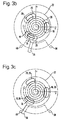
- the thermally controlled relief valve shown in section in FIG. 2 and in plan view in FIGS. 3a, 3b and 3c consists of three relief openings 16, 18 and 20 arranged in the wall 10a of the housing 10, which are arranged on a circle at equal angular intervals , a rotatable disc 22 and a spiral bimetallic spring 24.
- the disc 22 is provided with three through openings 26 which are of the same shape and arrangement as the relief openings 16, 18 and 20 and can be brought into alignment with them by rotating the disc 22.
- the disk 22 is rotatably mounted on a pin 30 which is supported by a bell-shaped cover part 32 which is fastened to the inside of the wall 10a and has through openings 34.
- the inner end of the spiral bimetallic spring 24 is connected to the pin 30 and its outer end to the washer 22.
- the disk 22 is provided with a radially projecting arm 36 which interacts with two stops 38, 40 which are attached to the inside of the wall 10a.
- the stops 38, 40 limit the angle of rotation of the disk 22.
- the spiral bimetallic spring 24 is deformed, causing its outer end connected to the disk 22 to be rotated clockwise. As a result, the disk 22 is rotated, the passage openings 26 of the disk 22 partially covering the relief openings 16, 18, 20. In this state, gas which is generated by one or more pyrotechnic gas generators arranged in the interior of the housing 10 can escape to the outside through the opening 34, the passage openings 26 and the relief openings 16, 18, 20.
- the disc 22 is rotated so far that the arm 36 abuts the stop 40. In this state, the passage openings 26 are brought into congruence with the relief openings 16, 18, 20, so that they are completely released.
Landscapes
- Physics & Mathematics (AREA)
- Fluid Mechanics (AREA)
- Engineering & Computer Science (AREA)
- Mechanical Engineering (AREA)
- Air Bags (AREA)
- Packaging Of Annular Or Rod-Shaped Articles, Wearing Apparel, Cassettes, Or The Like (AREA)
Description
- Die Erfindung betrifft eine Gassack-Baugruppe für ein Rückhaltesystem in Fahrzeugen, mit einem Gehäuse und wenigstens einem in diesem angeordneten pyrotechnischen Gasgenerator, wobei in der Wandung des Gehäuses wenigstens eine Entlastungsöffnung angeordnet ist, die durch ein Ventilelement verschließbar ist, wobei dieses Ventilelement durch ein auf eine Temperaturänderung ansprechendes Steuerelement bewegbar ist, welches die Entlastungsöffnung oder die Entlastungsöffnungen bei niedrigeren Umgebungstemperaturen verschließt und bei höheren Umgebungstemperaturen freigibt.
- Eine solche Gassack-Baugruppe ist aus der JP-A-01 229 739 bekannt. Die Aufgabe der Entlastungsöffnung besteht darin, oberhalb einer gewissen Umgebungstemperatur ein Entweichen eines Teils des vom Gasgenerator erzeugten Gases aus der Gassack-Baugruppe heraus zu ermöglichen. Der Hintergrund einer solchen Konstruktion ist darin zu sehen, daß Rückhaltesysteme in Fahrzeugen innerhalb eines weiten Temperaturbereichs von etwa -35°C bis +85°C funktionsfähig sein müssen. Aufgrund der Eigenschaften der verwendeten gaserzeugenden Stoffe schwankt innerhalb dieses Temperturbereiches die durch die Gassack-Baugruppe erzeugte Gasmenge um bis zu ± 25% gegenüber der bei Raumtemperatur erzeugten Gasmenge. Bei Temperaturen von 85°C und darüber hinaus wäre folglich die mechanische Belastung der durch den Gasgenerator aktivierten Teile des Rückhaltesystems, beispielsweise eines aufblasbaren Gassacks, übermäßig groß, wenn nicht ein Teil des erzeugten Gases entweichen könnte. Die aus dem oben genannten Dokument bekannt Gassack-Baugruppe ist mit einem Kolben versehen, der von einer temperaturabhängigen Feder beaufschlagt ist. In Abhängigkeit von der Umgebungstemperatur wird dieser Kolben derart verstellt, daß ein Durchgang vom Inneren der Gassack-Baugruppe zu Entlastungsöffnungen freigegeben wird. Allerdings ist die dort offenbarte Konstruktion sowohl hinsichtlich des Raumbedarfs als auch hinsichtlich des Gewichts unbefriedigend.
- Durch die Erfindung wird eine Gassack-Baugruppe der eingangs genannten Art geschaffen, die dadurch gekennzeichnet ist, daß die Entlastungsöffnung unterhalb von etwa 20°C verschlossen ist, zwischen etwa 20°C und etwa 85°C progressiv geöffnet wird und oberhalb von etwa 85°C vollständig geöffnet ist und daß das Ventilelement durch eine drehbare Scheibe gebildet ist, die eine in Deckung mit der Entlastungsöffnung in der Wandung des Gehäuses bewegbare Durchtrittsöffnung aufweist. Ein solches Ventilelement stellt einen Schieber mit minimalem Raumbedarf dar, der in einer Ebene senkrecht zur Gasdurchtrittsrichtung bewegt wird. Ferner ist die Antriebsleistung eines solchen Schiebers sehr gering.
- Gemäß einer bevorzugten Ausführungsform ist vorgesehen, daß das Steuerelement eine Bimetallfeder aufweist. Eine solche Feder ist besonders geeignet, das Ventilelement zu bewegen.
- Weitere vorteilhafte Ausgestaltungen der Erfindung sind in den Unteransprüchen gegeben.
- Weitere Merkmale und Vorteile der Erfindung ergeben sich aus der folgenden Beschreibung und aus der Zeichnung, auf die bezug genommen wird. In der Zeichnung zeigen:
- Fig. 1 eine Perspektivansicht einer Gassack-Baugruppe;
- Fig. 2 einen Schnitt durch ein thermisch gesteuertes Entlastungsventil in der Wandung des Gehäuses der Gassack-Baugruppe; und
- Figuren 3a, 3b und 3c schematische Darstellungen des Entlastungsventils in Draufsicht und in drei verschiedenen Stellungen.
- In der Wandung des Gehäuses 10 der in Fig. 1 gezeigten Gassack-Baugruppe sind zwei thermisch gesteuerte Entlastungsventile 12, 14 angeordnet. Die Anzahl dieser Entlastungsventile und ihre Anordnung können nach den jeweiligen Erfordernissen frei gewählt werden.
- Das in Fig. 2 im Schnitt und in den Figuren 3a, 3b und 3c in Draufsicht gezeigte, thermisch gesteuerte Entlastungsventil besteht aus drei in der Wandung 10a des Gehäuses 10 angeordneten Entlastungsöffnungen 16, 18 und 20, die auf einem Kreis in gleichen Winkelabständen angeordnet sind, einer drehbaren Scheibe 22 und einer spiralförmigen Bimetallfeder 24. Die Scheibe 22 ist mit drei Durchtrittsöffnungen 26 versehen, die von gleicher Form und Anordnung wie die Entlastungsöffnungen 16, 18 und 20 sind sowie mit diesen durch Drehung der Scheibe 22 in Deckung gebracht werden können. Die Scheibe 22 ist drehbar auf einem Zapfen 30 gelagert, der von einem glockenförmigen Deckelteil 32 getragen wird, welches an der Innenseite der Wandung 10a befestigt ist und Durchtrittsöffnungen 34 aufweist. Das innere Ende der spiralförmigen Bimetallfeder 24 ist an dem Zapfen 30 und ihr äußeres Ende an der Scheibe 22 angeschlossen. Die Scheibe 22 ist mit einem radial abstehenden Arm 36 versehen, der mit zwei Anschlägen 38, 40 zusammenwirkt, die an der Innenseite der Wandung 10a angebracht sind. Die Anschläge 38, 40 bewirken eine Begrenzung des Drehwinkels der Scheibe 22.
- Bei dem in den Figuren 2 und 3a gezeigten Zustand sind die Entlastungsöffnungen 16, 18, 20 durch die Scheibe 22 verschlossen. Dieser Zustand tritt bei Umgebungstemperaturen von etwa 20 °C und darunter ein. Die Drehstellung der Scheibe 22 wird durch den Anschlag 38 bestimmt.
- Bei höheren Temperaturen als etwa 20 °C tritt eine Verformung der spiralförmigen Bimetallfeder 24 ein, wodurch ihr äußeres, an die Scheibe 22 angeschlossenes Ende im Uhrzeigersinn verdreht wird. Folglich wird die Scheibe 22 verdreht, wobei die Durchtrittsöffnungen 26 der Scheibe 22 mit den Entlastungsöffnungen 16, 18, 20 teilweise zur Deckung kommen. In diesem Zustand kann Gas, welches durch einen oder mehrere im Inneren des Gehäuses 10 angeordnete, pyrotechnische Gasgeneratoren erzeugt wird, durch die Öffnung 34, die Durchtrittsöffnungen 26 und die Entlastungsöffnungen 16, 18, 20 nach außen entweichen.
- Bei weiterer Temperaturerhöhung wird die Scheibe 22 stärker verdreht, so daß die Entlastungsöffnungen 16, 18, 20 progressiv freigegeben werden. Dieser Zustand ist in Fig. 3b dargestellt.
- Bei Temperaturen von etwa 85 °C und darüber ist die Scheibe 22 so weit verdreht, daß der Arm 36 am Anschlag 40 anliegt. In diesem Zustand sind die Durchtrittsöffnungen 26 mit den Entlastungsöffnungen 16, 18, 20 zur Deckung gebracht, so daß diese vollständig freigegeben sind.
Claims (6)
- Gassack-Baugruppe für ein Rückhaltesystem in Fahrzeugen, mit einem Gehäuse (10) und wenigstens einem in diesem angeordneten pyrotechnischen Gasgenerator, wobei in der Wandung (10a) des Gehäuses wenigstens eine Entlastungsöffnung (16, 18, 20) angeordnet ist, die durch ein Ventilelement (22) verschließbar ist, wobei dieses Ventilelement (22) durch ein auf eine Temperaturänderung ansprechendes Steuerelement (24) bewegbar ist, welches die Entlastungsöffnung (16, 18, 20) bei niedrigeren Umgebungstemperaturen verschließt und bei höheren Umgebungstemperaturen freigibt, dadurch gekennzeichnet, daß die Entlastungsöffnung (16, 18, 20) unterhalb von etwa 20°C verschlossen ist, zwischen etwa 20°C und etwa 85°C progressiv geöffnet wird und oberhalb von etwa 85°C vollständig geöffnet ist und daß das Ventilelement durch eine drehbare Scheibe (22) gebildet ist, die eine in Deckung mit der Entlastungsöffnung (16, 18, 20) in der Wandung des Gehäuses bewegbare Durchtrittsöffnung (26) aufweist.
- Gassack-Baugruppe nach Anspruch 1, dadurch gekennzeichnet, daß die Scheibe (22) zwischen zwei Anschlägen (38, 40) drehbar ist.
- Gassack-Baugruppe nach einem der vorstehenden Ansprüche, dadurch gekennzeichnet, daß das Steuerelement eine Bimetallfeder (24) aufweist.
- Gassack-Baugruppe nach Anspruch 3, dadurch gekennzeichnet, daß die Bimetallfeder (24) spiralförmig ausgebildet und mit einem Ende an dem Gehäuse sowie mit dem anderen Ende an dem Ventilelement (22) angeschlossen ist.
- Gassack-Baugruppe nach einem der vorhergehenden Ansprüche, dadurch gekennzeichnet, daß die Entlastungsöffnung (16, 18, 20) entlang einer Kreislinie mit einem Radius, der dem mittleren Abstand der Entlastungsöffnung vom Drehpunkt der Scheibe (22) entspricht, gestreckt ausgebildet ist.
- Gassack-Baugruppe nach Anspruch 5, dadurch gekennzeichnet, daß auf der Kreislinie drei gestreckte Entlastungsöffnungen (16, 18, 20) in gleichen Winkelabständen angeordnet sind.
Applications Claiming Priority (2)
| Application Number | Priority Date | Filing Date | Title |
|---|---|---|---|
| DE4234510A DE4234510A1 (de) | 1992-10-13 | 1992-10-13 | Gassack-Baugruppe für ein Rückhaltesystem in Fahrzeugen |
| DE4234510 | 1992-10-13 |
Publications (2)
| Publication Number | Publication Date |
|---|---|
| EP0592879A1 EP0592879A1 (de) | 1994-04-20 |
| EP0592879B1 true EP0592879B1 (de) | 1996-07-03 |
Family
ID=6470366
Family Applications (1)
| Application Number | Title | Priority Date | Filing Date |
|---|---|---|---|
| EP93115797A Expired - Lifetime EP0592879B1 (de) | 1992-10-13 | 1993-09-30 | Gassack-Baugruppe für ein Rückhaltesystem in Fahrzeugen |
Country Status (3)
| Country | Link |
|---|---|
| EP (1) | EP0592879B1 (de) |
| DE (2) | DE4234510A1 (de) |
| ES (1) | ES2051259T3 (de) |
Cited By (1)
| Publication number | Priority date | Publication date | Assignee | Title |
|---|---|---|---|---|
| DE10027679C2 (de) * | 2000-06-03 | 2002-12-12 | Autoliv Dev | Airbag mit regelbarer Ventilation |
Families Citing this family (9)
| Publication number | Priority date | Publication date | Assignee | Title |
|---|---|---|---|---|
| US5513879A (en) * | 1994-05-04 | 1996-05-07 | Breed Automotive Technology, Inc. | Two stage inflator with module venting for passenger side airbags |
| US5551723A (en) * | 1994-07-20 | 1996-09-03 | Breed Automotive Technology, Inc. | Pulse shaping for airbag inflators |
| DE19628836C2 (de) * | 1996-07-17 | 2003-03-27 | Autoliv Dev | Gassackanordnung mit Ventilationsregelung |
| DE19810537A1 (de) * | 1998-03-11 | 1999-09-16 | Trw Airbag Sys Gmbh & Co Kg | Verfahren zum Steuern eines Fahrzeuginsassen-Rückhaltesystems und Fahrzeuginsassen-Rückhaltesystem |
| DE29812627U1 (de) | 1998-07-08 | 1999-01-07 | TRW Airbag Systems GmbH & Co. KG, 84544 Aschau | Gasgenerator |
| DE19912369A1 (de) * | 1999-03-19 | 2000-10-05 | Bsrs Restraint Syst Gmbh | Eigendynamisch gesteuertes Airbagmodul |
| DE102004001263A1 (de) * | 2004-01-08 | 2005-08-04 | Autoliv Development Ab | Airbagmodul |
| DE202004017429U1 (de) * | 2004-11-10 | 2005-03-17 | Trw Automotive Safety Sys Gmbh | Gassackmodul |
| PL212619B1 (pl) | 2008-05-02 | 2012-10-31 | Adaptronica Spolka Z Ograniczona Odpowiedzialnoscia | Zawór sterowany zwlaszcza do poduszki gazowej |
Family Cites Families (3)
| Publication number | Priority date | Publication date | Assignee | Title |
|---|---|---|---|---|
| US4394033A (en) * | 1981-02-26 | 1983-07-19 | The Firestone Tire & Rubber Company | Temperature compensating elastic cone |
| JPH01229739A (ja) * | 1988-03-11 | 1989-09-13 | Honda Motor Co Ltd | エアバッグの内圧調節装置 |
| DE4133506A1 (de) * | 1991-10-10 | 1993-04-15 | Dynamit Nobel Ag | Sicherheitseinrichtung zum schutz eines insassens eines kraftfahrzeuges gegen verletzungen beim aufprall |
-
1992
- 1992-10-13 DE DE4234510A patent/DE4234510A1/de not_active Withdrawn
-
1993
- 1993-09-30 ES ES93115797T patent/ES2051259T3/es not_active Expired - Lifetime
- 1993-09-30 EP EP93115797A patent/EP0592879B1/de not_active Expired - Lifetime
- 1993-09-30 DE DE59303125T patent/DE59303125D1/de not_active Expired - Fee Related
Cited By (1)
| Publication number | Priority date | Publication date | Assignee | Title |
|---|---|---|---|---|
| DE10027679C2 (de) * | 2000-06-03 | 2002-12-12 | Autoliv Dev | Airbag mit regelbarer Ventilation |
Also Published As
| Publication number | Publication date |
|---|---|
| EP0592879A1 (de) | 1994-04-20 |
| DE4234510A1 (de) | 1994-04-21 |
| ES2051259T1 (es) | 1994-06-16 |
| ES2051259T3 (es) | 1996-11-01 |
| DE59303125D1 (de) | 1996-08-08 |
Similar Documents
| Publication | Publication Date | Title |
|---|---|---|
| DE102010009375A1 (de) | Dämpfereinrichtung | |
| DE102012000443A1 (de) | Shape memory alloy actuated hvac outlet airflow baffle controllers | |
| DE102015108284A1 (de) | Turbolader | |
| DE102004020655A1 (de) | Verriegelungseinheit für ein bewegliches Schließelement | |
| CH617756A5 (de) | ||
| EP0272373B1 (de) | Drosselklappenstutzen für eine Brennkraftmaschine | |
| EP0592879A1 (de) | Gassack-Baugruppe für ein Rückhaltesystem in Fahrzeugen | |
| DE2557077A1 (de) | Bedienungsvorrichtung fuer ein uebertragungsorgan in kraftfahrzeugen | |
| DE4119613A1 (de) | Flugkoerper mit ruderblaettern | |
| DE2117276C3 (de) | Einstellbarer Drehwiderstand | |
| DE102010039821A1 (de) | Behälter mit geteiltem Deckel | |
| DE10137175A1 (de) | Motorabdeckung eines Kraftfahrzeugs mit wenigstens einer Be- und/oder Entlüftungsöffnung, mit einem Verschlusselement zum Verschließen der Be- und/oder Entlüftungsöffnung | |
| DE3931905A1 (de) | Verbindungseinrichtung in form eines nach art einer uhrfeder angeordneten flexiblen elektrischen kabels | |
| DE102014118504A1 (de) | Scharniervorrichtung für eine Kofferraumklappe | |
| DE3044289A1 (de) | Belueftungsduese, insbesondere fuer den fahrgastraum eines fahrzeuges | |
| DE1632629A1 (de) | Zuendvorrichtung fuer ein Gasfeuerzeug | |
| DE2040641A1 (de) | Schwenkduese fuer Belueftungs- oder Beheizungssysteme | |
| EP3606779A1 (de) | Luftleitelement mit reibelement und luftausströmer | |
| DE9412661U1 (de) | Verriegelungsvorrichtung | |
| DE2607245A1 (de) | Mehrwegventil | |
| DE102020112228A1 (de) | Fahrzeug | |
| DE916368C (de) | Elektrischer Anlassmotor fuer Brennkraftmaschinen von Kraftfahrzeugen | |
| DE3219296C2 (de) | ||
| WO2000071391A1 (de) | Airbagvorrichtung und auslöseverfahren dafür | |
| DE102021211893A1 (de) | Kugelhahn, insbesondere zur Explosionsentkopplung in Prozessrohrleitungen |
Legal Events
| Date | Code | Title | Description |
|---|---|---|---|
| PUAI | Public reference made under article 153(3) epc to a published international application that has entered the european phase |
Free format text: ORIGINAL CODE: 0009012 |
|
| AK | Designated contracting states |
Kind code of ref document: A1 Designated state(s): DE ES FR GB IT SE |
|
| GBC | Gb: translation of claims filed (gb section 78(7)/1977) | ||
| REG | Reference to a national code |
Ref country code: ES Ref legal event code: BA2A Ref document number: 2051259 Country of ref document: ES Kind code of ref document: T3 |
|
| ITCL | It: translation for ep claims filed |
Representative=s name: DR. ING. A. RACHELI & C. |
|
| 17P | Request for examination filed |
Effective date: 19940513 |
|
| EL | Fr: translation of claims filed | ||
| 17Q | First examination report despatched |
Effective date: 19950724 |
|
| GRAG | Despatch of communication of intention to grant |
Free format text: ORIGINAL CODE: EPIDOS AGRA |
|
| GRAH | Despatch of communication of intention to grant a patent |
Free format text: ORIGINAL CODE: EPIDOS IGRA |
|
| RAP1 | Party data changed (applicant data changed or rights of an application transferred) |
Owner name: TRW OCCUPANT RESTRAINT SYSTEMS GMBH |
|
| GRAH | Despatch of communication of intention to grant a patent |
Free format text: ORIGINAL CODE: EPIDOS IGRA |
|
| GRAA | (expected) grant |
Free format text: ORIGINAL CODE: 0009210 |
|
| AK | Designated contracting states |
Kind code of ref document: B1 Designated state(s): DE ES FR GB IT SE |
|
| REF | Corresponds to: |
Ref document number: 59303125 Country of ref document: DE Date of ref document: 19960808 |
|
| ET | Fr: translation filed | ||
| ITF | It: translation for a ep patent filed | ||
| GBT | Gb: translation of ep patent filed (gb section 77(6)(a)/1977) |
Effective date: 19960819 |
|
| REG | Reference to a national code |
Ref country code: ES Ref legal event code: FG2A Ref document number: 2051259 Country of ref document: ES Kind code of ref document: T3 |
|
| PLBE | No opposition filed within time limit |
Free format text: ORIGINAL CODE: 0009261 |
|
| STAA | Information on the status of an ep patent application or granted ep patent |
Free format text: STATUS: NO OPPOSITION FILED WITHIN TIME LIMIT |
|
| 26N | No opposition filed | ||
| PGFP | Annual fee paid to national office [announced via postgrant information from national office to epo] |
Ref country code: SE Payment date: 19970718 Year of fee payment: 5 |
|
| PG25 | Lapsed in a contracting state [announced via postgrant information from national office to epo] |
Ref country code: SE Free format text: LAPSE BECAUSE OF NON-PAYMENT OF DUE FEES Effective date: 19981001 |
|
| EUG | Se: european patent has lapsed |
Ref document number: 93115797.8 |
|
| PGFP | Annual fee paid to national office [announced via postgrant information from national office to epo] |
Ref country code: GB Payment date: 20000807 Year of fee payment: 8 |
|
| PGFP | Annual fee paid to national office [announced via postgrant information from national office to epo] |
Ref country code: FR Payment date: 20000905 Year of fee payment: 8 |
|
| PGFP | Annual fee paid to national office [announced via postgrant information from national office to epo] |
Ref country code: ES Payment date: 20000926 Year of fee payment: 8 |
|
| PG25 | Lapsed in a contracting state [announced via postgrant information from national office to epo] |
Ref country code: GB Free format text: LAPSE BECAUSE OF NON-PAYMENT OF DUE FEES Effective date: 20010930 |
|
| PG25 | Lapsed in a contracting state [announced via postgrant information from national office to epo] |
Ref country code: ES Free format text: LAPSE BECAUSE OF NON-PAYMENT OF DUE FEES Effective date: 20011001 |
|
| REG | Reference to a national code |
Ref country code: GB Ref legal event code: IF02 |
|
| GBPC | Gb: european patent ceased through non-payment of renewal fee |
Effective date: 20010930 |
|
| PG25 | Lapsed in a contracting state [announced via postgrant information from national office to epo] |
Ref country code: FR Free format text: LAPSE BECAUSE OF NON-PAYMENT OF DUE FEES Effective date: 20020531 |
|
| REG | Reference to a national code |
Ref country code: FR Ref legal event code: ST |
|
| REG | Reference to a national code |
Ref country code: ES Ref legal event code: FD2A Effective date: 20021011 |
|
| PG25 | Lapsed in a contracting state [announced via postgrant information from national office to epo] |
Ref country code: IT Free format text: LAPSE BECAUSE OF NON-PAYMENT OF DUE FEES;WARNING: LAPSES OF ITALIAN PATENTS WITH EFFECTIVE DATE BEFORE 2007 MAY HAVE OCCURRED AT ANY TIME BEFORE 2007. THE CORRECT EFFECTIVE DATE MAY BE DIFFERENT FROM THE ONE RECORDED. Effective date: 20050930 |
|
| PGFP | Annual fee paid to national office [announced via postgrant information from national office to epo] |
Ref country code: DE Payment date: 20050930 Year of fee payment: 13 |
|
| PG25 | Lapsed in a contracting state [announced via postgrant information from national office to epo] |
Ref country code: DE Free format text: LAPSE BECAUSE OF NON-PAYMENT OF DUE FEES Effective date: 20070403 |