EP0592829B1 - Mit Schützen zu kombinierendes Überlastrelais - Google Patents
Mit Schützen zu kombinierendes Überlastrelais Download PDFInfo
- Publication number
- EP0592829B1 EP0592829B1 EP93114815A EP93114815A EP0592829B1 EP 0592829 B1 EP0592829 B1 EP 0592829B1 EP 93114815 A EP93114815 A EP 93114815A EP 93114815 A EP93114815 A EP 93114815A EP 0592829 B1 EP0592829 B1 EP 0592829B1
- Authority
- EP
- European Patent Office
- Prior art keywords
- contactors
- combined
- overload relay
- phase
- contactor
- Prior art date
- Legal status (The legal status is an assumption and is not a legal conclusion. Google has not performed a legal analysis and makes no representation as to the accuracy of the status listed.)
- Expired - Lifetime
Links
Images

Classifications
-
- H—ELECTRICITY
- H01—ELECTRIC ELEMENTS
- H01H—ELECTRIC SWITCHES; RELAYS; SELECTORS; EMERGENCY PROTECTIVE DEVICES
- H01H11/00—Apparatus or processes specially adapted for the manufacture of electric switches
- H01H11/0006—Apparatus or processes specially adapted for the manufacture of electric switches for converting electric switches
- H01H11/0031—Apparatus or processes specially adapted for the manufacture of electric switches for converting electric switches for allowing different types or orientation of connections to contacts
-
- H—ELECTRICITY
- H01—ELECTRIC ELEMENTS
- H01H—ELECTRIC SWITCHES; RELAYS; SELECTORS; EMERGENCY PROTECTIVE DEVICES
- H01H83/00—Protective switches, e.g. circuit-breaking switches, or protective relays operated by abnormal electrical conditions otherwise than solely by excess current
- H01H83/20—Protective switches, e.g. circuit-breaking switches, or protective relays operated by abnormal electrical conditions otherwise than solely by excess current operated by excess current as well as by some other abnormal electrical condition
- H01H83/22—Protective switches, e.g. circuit-breaking switches, or protective relays operated by abnormal electrical conditions otherwise than solely by excess current operated by excess current as well as by some other abnormal electrical condition the other condition being imbalance of two or more currents or voltages
- H01H83/223—Protective switches, e.g. circuit-breaking switches, or protective relays operated by abnormal electrical conditions otherwise than solely by excess current operated by excess current as well as by some other abnormal electrical condition the other condition being imbalance of two or more currents or voltages with bimetal elements
-
- H—ELECTRICITY
- H01—ELECTRIC ELEMENTS
- H01H—ELECTRIC SWITCHES; RELAYS; SELECTORS; EMERGENCY PROTECTIVE DEVICES
- H01H11/00—Apparatus or processes specially adapted for the manufacture of electric switches
- H01H11/0006—Apparatus or processes specially adapted for the manufacture of electric switches for converting electric switches
- H01H11/0031—Apparatus or processes specially adapted for the manufacture of electric switches for converting electric switches for allowing different types or orientation of connections to contacts
- H01H2011/0037—Apparatus or processes specially adapted for the manufacture of electric switches for converting electric switches for allowing different types or orientation of connections to contacts with removable or replaceable terminal blocks
-
- H—ELECTRICITY
- H01—ELECTRIC ELEMENTS
- H01H—ELECTRIC SWITCHES; RELAYS; SELECTORS; EMERGENCY PROTECTIVE DEVICES
- H01H89/00—Combinations of two or more different basic types of electric switches, relays, selectors and emergency protective devices, not covered by any single one of the other main groups of this subclass
- H01H89/06—Combination of a manual reset circuit with a contactor, i.e. the same circuit controlled by both a protective and a remote control device
Definitions
- the invention relates to overload relays according to the preamble of claim 1.
- it relates to overload relays with thermally delayed overcurrent tripping, with magnetic short-circuit tripping or with a combination of both types of tripping, but also with overload relays equipped with current transformers.
- a typical area of application is motor protection.
- An overload relay to be combined with a contactor with bimetal releases for each current phase to be protected is known from FR 2 625 603 A1.
- this overload relay On the side facing the contactor, this overload relay has fixed built-in plug connections as phase connections, which can be connected to the terminal connections of the contactor.
- the plug connections On the one hand, the plug connections are in the phase distance and in the phase height, i.e.
- the connection geometry is compatible with the terminal connections of the contactor and, on the other hand, the overload relay can be snapped onto the contactor.
- the overload relay On the side facing the load, the overload relay has permanently installed terminal connections as phase connections.
- the terminal connections of the overload relay do not match the terminal connections of the contactor in terms of their connection geometry, which makes it difficult for the user to configure, install, maintain and maintain.
- the scope of application is limited to the combination with contactors of the same type and size. It is not possible to set up the components often with this solution.
- the overload relay is provided on both sides with flat connections that have holes for screw connections and are compatible with the flat connections of the contactor in terms of their connection type and geometry.
- the disadvantage of these solutions remains that the overload relays cannot be combined with contactors of different connection types and geometries, or only in a complex manner. Comparable problems arise with regard to different phase conductors coming from the overload relay and leading to the load.
- an overload relay with load-side terminal connections is designed as a basic device, to which a contact-side connection block designed as a housing-free connection angle module is screwed in a height-adjustable manner within certain limits.
- the connection brackets are plug-in connections which enable direct connection to a contactor - but only if the contactor is equipped with terminal connections.
- the overload relay can only be attached to an assembly base using the basic device.
- a connection block with terminal connections is provided for the individual installation of the overload relay.
- an overload relay is known from DE 84 34 232 U1 that consists of a basic device with load-side terminal connections and a contactor-side, housing-encapsulated connection block.
- the connection block is detachably connected electrically via plug connections and mechanically to the basic device via snap connections.
- the overload relay With a connection block provided with terminal connections, the overload relay is suitable for stand-alone installation.
- the overload relay can be combined directly with a contactor thanks to a connection block provided with plug connections - but only if this is equipped with terminal connections.
- the overload relay can also be connected to contactors with different phase spacings by selecting the elbow of the plug connections.
- the load-side compatibility of the overload relay with regard to the phase distance of a contactor is also provided - however, a load-side adaptation to contactors with different phase distances is not possible. It can only be attached to an assembly base using the basic device. The plug connection between the basic device and the connection block makes the overload relay unsuitable for use in higher current ranges.
- a switching device known according to EP 219 570 A1 with actuatable main contact bridges and with associated fixed contact rails, each leading out of opposite side walls of the switch housing, is provided on each of these side walls with a housing bracket.
- the housing brackets contain the connection screws required for connection with ordinary connecting cables and can be attached in two positions rotated by 180 ° to one another, so that the connection screws can be actuated either from the front or the rear of the housing, the housing brackets via the free ends of the Grip the fixed contact rails and connect them with the connecting screws.
- An electromagnetic switching device known from DE 30 37 405 A1 has a housing part which is detachably connected to insulating material bodies. For each pole to be switched, a connection terminal and a fixed contact rail permanently connected to it are embedded in the insulating bodies.
- the insulating material bodies are suitable for being able to change the number and / or the quality of the fixed contact rails for the purpose of adaptation to the requirements of the contactor. With different fixed contact rails, both terminal connections and flat plug connections for cable or wire connections can be implemented within the connection openings of the insulating body.
- connection blocks that can be connected to the basic device in a simple manner can be the same or different on the contactor and load side in order to meet the most varied connection and combination possibilities with regard to the associated contactor and the load side.
- the modules of the overload relay can each be mounted individually or conveniently only via the connection blocks on the assembly base. When assembled together, the basic device is also supported. The latter takes place in a particularly advantageous manner via the mechanical and electrical connection of the connection blocks to the basic device.
- the compatibility of the terminal block on the contactor side serves in particular to directly connect the overload relay and contactor.
- the sub-claim 2 specifies an advantageous embodiment of the solution according to claim 1.
- the load-side compatibility of the connection block facilitates, among other things. for the user, the geometric and functional assignment of the load side of the overload relay to the output side of the contactor and thus promotes understanding of the system (so-called recognition value and degree of familiarity).
- the terminal blocks come from a series which advantageously meet the connection conditions for combining the overload relay with different contactors, which - apart from the differences in the electrical parameters - differ in terms of their connection type, their phase height and their phase spacing.
- the connection blocks thus also satisfy different embodiments of phase conductors on the output side or, if appropriate, downstream switching devices.
- the terminal blocks of the series can in principle be used both on the contactor side and on the load side. For a multitude of combinations with different contactors, this flexible module system - of course taking into account the electrical conditions - only requires a single basic device of the overload relay.
- the base unit can be adapted to the respective connection conditions in a suitable, generally different manner, both on the contactor side and on the load side.
- the module system can be adapted to any newly developed contactor in a contactor series and any other to a newly developed contactor series from the same manufacturer or to contactors from other manufacturers. It is also possible to retrofit a circuit with a contactor with an overload relay, whereby - as is generally desired - the load-side connection type and connection geometry can be obtained, which brings considerable advantages for the user, inter alia through the use of the same tools for connecting the contactor and Overload relay.
- claim 4 and in particular of claim 5 are reliable means for the simultaneous mechanical and electrical connection of the terminal blocks with the basic device.
- the features of claims 6 and 7 are used to adapt the overload relay to different phase distances and heights.
- the basic device is a fully-fledged device for overload protection in electrical terms. In this case, the connections on the contactor and load side could possibly be made via the means of the screw connections on the basic device.
- the plug connections according to claim 8 enable in particular the direct connection of the overload relay to a contactor via its relay-side terminal connections. It is particularly advantageous if an identically constructed plug-in block of the contactor is used as the connection block.
- the design of the plug connections according to claim 10 results in a particularly advantageous connection possibility between the connection block and the basic device.
- the flat connections of the plug connections designed according to claim 11 allow not only the plug connection via terminal connections of a contactor but also the screw connection with flat connections a contactor or with incoming or outgoing flat conductors.
- the feature according to claim 12, in particular in a simple embodiment according to claim 13, allows the phase connections of the overload relay to be adapted to the phase height of the relay-side contactor connections or to other incoming or outgoing connections or conductors within certain limits.
- an overload relay provided with plug-in connections can be retrofitted with terminal connections in order, for example, to enable its individual installation in a simple manner. It is particularly advantageous if, according to claim 15, a terminal carrier that can be taken over by the contactor is used, which, for example, when the terminal carrier is used on the load side in the interest of understanding the system for the user, gives the same visual impression at the outputs of the contactor and the overload relay.
- the terminal connections according to claim 16 also serve for the individual installation of the overload relay and for easier understanding of the system.
- the arrangement of the screw connection between the terminal block and basic device according to claim 17 is particularly useful.
- a terminal block which can be taken over by the contactor has the advantages already mentioned with claim 15.
- the use of box terminals according to claim 19 is also expedient.
- the covering of the terminal connections according to claim 20 serves to protect against contact and is particularly expedient in the case of a cover hood that can be taken over by the contactor according to claim 21.
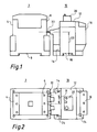
- the contactor contains, for each of the three phases, mains-side terminal connections 4 and relay-side terminal connections 6.
- the contactor 2 also contains snap fastening means 8 for snapping the contactor 2 onto a top-hat rail, not shown.
- the overload relay 10 consists of a basic device 12, a contactor-side connection block 14 and a load-side connection block 16.
- the basic device 12 contains known overload protection devices for protecting the downstream load against overload, in particular against overcurrent, and is encapsulated in a molded housing.
- the basic device 12 has snap fastening means 18 on its underside.
- An auxiliary switch 20 known per se is attached to its upper side.
- the contactor-side connection block 14 is encapsulated in a molded housing and contains three phase connections designed as plug connections 22, which project into the terminal spaces of the relay-side terminal connections 6 of the contactor 2 and are connected to them. There is thus compatibility, that is to say both the type of connection as well as the connection geometry defined by the phase distance 21 and the phase height 23, between the relay-side phase connections of the contactor 2 and the contactor-side phase connections of the overload relay 10.
- the load-side connection block 16 is also encapsulated in a molded housing and contains three phase connections designed as terminal connections.
- the connection blocks 14 and 16 each have on their undersides two screw fastening means 24 in the form of lateral approaches with openings.
- the three modules basic device 12, contactor-side connection block 14 and load-side connection block 16 are mechanically and electrically connected to one another in a manner described in more detail below.
- the overload relay 10 can either be fastened on a top hat rail (not shown) using the snap fastening means 18 of the basic device 12 or solely on a mounting plate using the screw fastening means 24 of the connection blocks 14 and 16.
- the overload relay 10 corresponds in its load-side connection type and geometry to the relay-side connection type and geometry of the contactor 2. This coincidence of the phase connections considerably simplifies the understanding of the system and the handling of the system components by the recognition effect for the user.
- connection plates 34 made of conductive material are fastened in phases by means of grooves 36 and retaining screws 38.
- the connection plates 34 are partially accessible from the outside through rectangular openings 40 and have threaded bores 42 in these areas.
- connection plates 34, grooves 36, retaining screws 38, openings 40, threaded holes 42, blind holes 44, connecting lugs 46 and openings 48 are arranged on the opposite molded housing surface facing the contact-side connection block 14.
- the contactor-side connection block 14 consists of a molded housing in the form of a rib-reinforced molded shell 50 and the three plug connections 22.
- the plug connections 22 merge in one piece into a first connection piece 52 bent at right angles.
- the plug connections 22 or connecting pieces 52 are inserted between two L-shaped protrusions 54 which are directed upwards and arranged approximately in phase height. They are limited in their vertical movement downwards by the upper inner transverse rib 56 and upwards by applying two lateral stop angles 58 of the first connection pieces 52 to the upper, horizontal legs of the L-shaped formations 54.
- the inserted plug connections 22 or connection pieces 52 are limited by the application of the stop angle 58 to the lower, vertical legs of the L-shaped formations 54.
- two downward-pointing connecting pins 60 are formed on the lower part of the molded shell 50 and two pins 62 directed towards the basic device 12 in the upper half of the molded shell 50.
- the actual electrical and mechanical connection is made by three socket head screws 64, each of which extends with its shaft through an elongated hole 66 of the vertically directed legs of the first connecting pieces 52 and is screwed into the threaded bores 42 of the associated connecting plates 34 of the basic device 12. This is done with the aid of a screwdriver 68, which engages with its tip through a screw opening 70 inserted in the molded shell 50 below the plug connections 22 and acts in the direction of the phase access.
- the type of mounting of the plug connections 22 or connection pieces 52 in the molded shell 50 and the connection via the elongated holes 66 allow, within certain limits, the phase height of the plug connections 22 - and thus the phase height of the overload relay on the contactor side - to be adapted to the phase height of the upstream contactor .
- the load-side connection block 16 consists of a further molded housing 72 and three clamp connections mounted therein, which are designed as frame clamps 74.
- a second connection piece 78 which is bent at right angles, is inserted between two parallelepiped-shaped formations 76 of the further molded housing 72 in the middle height of the frame clamps 74.
- the load-side connection block 16 is locked in the associated openings 48 and blind holes 44 of the basic device 12 by means of two connecting pins 60 and two pins 62.
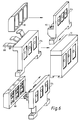
- FIG. 6 illustrates how the basic device 12 can be connected on the contactor side in addition to the contact-side connection block 14 described with FIG. 4 with a selection of further connection blocks 114, 214, and 314 from a series in order to meet a wide variety of connection conditions.
- the contactor-side connection block 114 shown in the lower part of the figure is provided with plug-in connections designed to form flat connections 82 and provided with connecting bores 84.
- the flat connections 82 can be clamped directly to suitable terminal connections of a contactor, they can be screwed directly to compatible flat connections of a contactor, but they can also be connected to flat conductors when the components of the contactor and overload relay are installed individually, which are connected at the other end to a contactor.
- connection carrier designed as a box terminal block 86 is pushed onto the flat connections 82 and mechanically and electrically connected to them via screws, not shown.
- An additional advantage here is that a connection carrier is used as box terminal block 86, which comes from the contactor series to be combined with the overload relay.
- the contact-side connection block 214 shown in the middle also has plug connections 88 as phase connections, which merge in one piece into third connection pieces 89. In order to establish compatibility with regard to the connection geometry of larger contactors, the third connection pieces 89 were made in two to one another vertical directions.
- the contactor-side connection block 314 shown in the upper part of the figure is used for the individual installation of the components and is equipped with known terminal connections, into which the phase conductors coming from the contactor can be hung from above. After the phase conductors have been connected, the terminal connections 90 are secured against contact by a cover 92 which can be fitted from the front. A further advantage here is that the cover 92 was taken over by a contactor of the row of contactors to be combined with the overload relay.
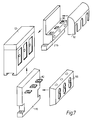
- FIG. 7 illustrates how the basic device 12 can be connected on the load side in addition to the load-side connection block 16 described with FIG. 5, with a selection of further connection blocks 116 and 216 from a series, in order to satisfy the most varied of closing conditions.
- the load-side connection block 116 shown in the lower part of the figure is identical to the contact-side connection block 114 from FIG. 6.
- the flat connections 82 are connected to flat conductors which are connected at the other end to the load. If necessary, the box terminal block 86 already described with FIG. 6 can be placed on the flat connections 82.
- the load-side connection block 216 with terminal connections 90 shown in the upper part of FIG. 7 is in turn identical to the protective-side connection block 314 explained in more detail in FIG. 6.
- the cover 92 has also already been described there.
Landscapes
- Engineering & Computer Science (AREA)
- Manufacturing & Machinery (AREA)
- Connections Arranged To Contact A Plurality Of Conductors (AREA)
- Fuses (AREA)
Description
- Die Erfindung betrifft Überlastrelais nach dem Oberbegriff des Anspruches 1. Insbesondere betrifft es Überlastrelais mit thermisch verzögerter Überstromauslösung, mit magnetischer Kurzschlußauslösung oder mit einer Kombination beider Auslösearten, aber auch mit Stromwandlern ausgestattete Überlastrelais. Ein typisches Anwendungsgebiet ist der Motorschutz.
- Ein mit einem Schütz zu kombinierendes Überlastrelais mit Bimetallauslösern für jede zu schützende Stromphase ist aus der FR 2 625 603 A1 bekannt. Dieses Überlastrelais weist auf der zum Schütz gerichteten Seite als Phasenanschlüsse festeingebaute Steckanschlüsse auf, die mit Klemmanschlüssen des Schützes verbindbar sind. Dazu sind zum einen die Steckanschlüsse im Phasenabstand und in der Phasenhöhe, d.h. in der Anschlußgeometrie kompatibel mit den Klemmanschlüssen des Schützes ausgeführt und ist zum anderen das Überlastrelais auf dem Schütz aufschnappbar. Auf der zur Last gerichteten Seite weist das Überlastrelais als Phasenanschlüsse festeingebaute Klemmanschlüsse auf. Die Klemmanschlüsse vom Überlastrelais stimmen in der Anschlußgeometrie nicht mit den Klemmanschlüssen des Schützes überein, was für den Anwender ein Erschwernis beim Projektieren, Installieren, Warten und Instandhalten darstellt. Außerdem ist der Anwendungsumfang auf die Kombination mit Schützen gleicher Bauart und -größe beschränkt. Eine oft erwünschte Einzelaufstellung der Komponenten ist bei dieser Lösung nicht möglich.
- Aus dem Siemens-Katalog NS 2/1991 (S. 4/13 u. 11/7, 8, 23) ist zu ersehen, daß ein thermisch verzögertes Überlastrelais 3UA60 schützseitig mit festeingebauten, flachanschlußartigen Steckanschlüssen, die kompatibel zu den mit ihnen zu verbindenden relaisseitigen Klemmanschlüssen eines Schützes 3TF50 sind, versehen ist und zusätzliche Mittel zum Aufschnappen auf eine Hutschiene oder zum Anschrauben an eine Montageplatte enthält. Die lastseitigen Klemmanschlüsse des Überlastrelais stimmen in ihrer Anschlußgeometrie mit den relaisseitigen Klemmanschlüssen des Schützes überein, was erleichternd für die Anwendung ist. Diese Lösung erlaubt auch die Einzelaufstellung der Komponenten, indem ein als Rahmenklemmenblock ausgebildeter Anschlußträger 3UX1 424 über die Steckanschlüsse des Überlastrelais geschoben und mit diesen verbunden wird, um so das Anschließen der Phasenleiter zu ermöglichen. Bei einer weiteren Kombination aus einem Schütz 3TF51 und einem Überlastrelais 3UA61 ist das Überlastrelais beidseitig mit Flachanschlüssen versehen, die Bohrungen für Schraubanschlüsse aufweisen und hinsichtlich ihrer Anschlußart und -geometrie kompatibel zu den Flachanschlüssen des Schützes sind. Als Nachteil dieser Lösungen verbleibt, daß die Überlastrelais nicht oder nur in aufwendiger Weise mit Schützen verschiedener Anschlußarten und -geometrien kombinierbar sind. Vergleichbare Probleme ergeben sich im Hinblick auf unterschiedliche vom Überlastrelais abgehende und zur Last führende Phasenleiter.
- Nach KLÖCKNER-MOELLER-POST, Heft 89, April 1976, S. 27-32 ist ein mit lastseitigen Klemmanschlüssen versehenes Überlastrelais als Grundgerät ausgebildet, an den ein als gehäuseloser Anschlußwinkel-Baustein ausgebildeter schützseitiger Anschlußblock in gewissen Grenzen höhenverstellbar angeschraubt wird. Die Anschlußwinkel sind Steckanschlüsse, welche die direkte Verbindung mit einem Schütz ermöglichen - jedoch nur, wenn das Schütz mit Klemmanschlüssen ausgestattet ist. Die Befestigung des Überlastrelais auf einer Montageunterlage kann nur über das Grundgerät erfolgen. Durch die Bereitstellung unterschiedlicher Anschlußblöcke ist die schützseitige Anpassung des Überlastrelais an Schütze einer Baureihe mit unterschiedlicher Phasengeometrie möglich - dies gilt jedoch nicht für die Lastseite des Überlastrelais. Für die Einzelaufstellung des Überlastrelais ist ein mit Klemmanschlüssen versehener Anschlußblock vorgesehen. Weiterhin ist aus der DE 84 34 232 U1 ein Überlastrelais bekannt, daß aus einem Grundgerät mit lastseitigen Klemmanschlüssen und einem schützseitigen, gehäusegekapselten Anschlußblock besteht. Der Anschlußblock ist lösbar über Steckverbindungen elektrisch und über Rastverbindungen mechanisch mit dem Grundgerät verbunden. Mit einem mit Klemmanschlüssen versehenen Anschlußblock ist das Überlastrelais zur Einzelaufstellung geeignet. Durch einen mit Steckanschlüssen versehenen Anschlußblock ist das Überlastrelais direkt mit einem Schütz kombinierbar - allerdings nur, wenn dieses mit Klemmanschlüssen ausgestattet ist. Durch entsprechende Wahl der Abkröpfung der Steckanschlüsse, kann das Überlastrelais auch an Schütze mit unterschiedlichen Phasenabständen angeschlossen werden. Es ist auch die lastseitige Kompatibilität des Überlastrelais hinsichtlich des Phasenabstandes eines Schützes vorgesehen - eine lastseitige Anpassung an Schütze mit unterschiedlichen Phasenabständen ist jedoch nicht möglich. Die Befestigung auf einer Montageunterlage kann nur über das Grundgerät erfolgen. Die Steckverbindung zwischen Grundgerät und Anschlußblock macht das Überlastrelais für die Anwendung in höheren Strombereichen ungeeignet.
- Ein nach der EP 219 570 A1 bekanntes Schaltgerät mit betätigbaren Hauptkontaktbrücken und mit jeweils aus gegenüberliegenden Seitenwänden des Schaltergehäuses herausgeführten zugehörigen Festkontaktschienen ist an diesen Seitenwänden mit je einem Gehäuseböckchen versehen. Die Gehäuseböckchen enthalten die zum Verbinden mit gewöhnlichen Anschlußleitungen erforderlichen Anschlußschrauben und sind wahlweise in zwei um 180° zueinander gedrehten Stellungen anbringbar, so daß die Anschlußschrauben entweder von der Vorder- oder der Rückseite des Gehäuses her betätigbar sind, wobei die Gehäuseböckchen über die freien Enden der Festkontaktschienen greifen und mit diesen durch die Anschlußschrauben verbunden werden. Auch dieser Lösung läßt sich bei Übertragung auf Überlastrelais kein Hinweis darüber entnehmen, wie eine sowohl schützseitige als auch lastseitige Anpassung an verschiedene Anschlußarten und -geometrien sowie eine andersartige als allein über das Grundgerät erfolgende Montagebefestigung vorgenommen werden könnte.
- Ein nach der DE 30 37 405 A1 bekanntes elektromagnetisches Schaltgerät weist ein Gehäuseteil auf, das mit Isolierstoffkörpern lösbar verbunden ist. In den Isolierstoffkörpern sind für jeden zu schaltenden Pol eine Anschlußklemme und eine damit unlösbar verbundene Festkontaktschiene eingebettet. Die Isolierstoffkörper sind geeignet, eine Veränderung der Anzahl und/oder der Güte der Festkontaktschienen zwecks Anpassung an die Erfordernisse des Schaltschützes vornehmen zu können. Mit unterschiedlicher Festkontaktschienen lassen sich sowohl Klemmanschlüsse als auch Flachsteckanschlüsse für Kabel- oder Drahtverbindungen innerhalb der Anschlußöffnungen des Isolierstoffkörpers realisieren.
- Daraus ergibt sich die Aufgabe der Erfindung, mit einem gattungsgemäßen Überlastrelais bei verschiedenartigen Befestigungsmöglichkeiten in einfacher und anwenderfreundlicher Weise die Kombination mit sich hinsichtlich ihrer Anschlußart und -geometrie unterscheidenden Schützen sowie abgangsseitigen Phasenleitern zu gestatten.
- Die Aufgabe wird erfindungsgemäß durch die Merkmale des Anspruches 1 gelöst. Beide in einfacher Weise mit dem Grundgerät verbindbaren Anschlußblöcke können schütz- und lastseitig gleich oder unterschiedlich sein, um den unterschiedlichsten Anschluß- und Kombinationsmöglichkeiten hinsichtlich des zugehörigen Schützes und der Lastseite zu genügen. Mit dieser Modulbauweise kann auf einfache Art entweder eine direkte Verbindung des Überlastrelais mit dem zu kombinierenden Schütz oder eine indirekte Verbindung, insbesondere eine Einzelaufstellung, beider Komponenten realisiert werden. Die Module des Überlastrelais können jedes für sich oder zweckmäßigerweise gemeinsam nur über die Anschlußblöcke auf der Montageunterlage montiert werden. Bei gemeinsamer Montage wird das Grundgerät mit gehaltert. In besonders vorteilhafter Weise geschieht letzteres über die mechanische und elektrische Verbindung der Anschlußblöcke zum Grundgerät. Die schützseitige Kompatibilität des Anschlußblockes dient insbesondere der direkten Verbindbarkeit von Überlastrelais und Schütz.
- Der Unteranspruch 2 gibt eine vorteilhafte Ausgestaltung der Lösung nach Anspruch 1 an. Die lastseitige Kompatibilität des Anschlußblockes erleichtert u.a. für den Anwender die geometrische und funktionelle Zuordnung der Lastseite des Überlastrelais zu der Ausgangsseite des Schützes und fördert damit das Systemverständnis (sogenannter Wiedererkennungswert und Vertrautheitsgrad).
- Nach Unteranspruch 3 entstammen die Anschlußblöcke einer Baureihe, welche in vorteilhafter Weise den Anschlußbedingungen zur Kombination des überlastrelais mit unterschiedlichen Schützen genügen, die sich - abgesehen von den Unterschieden in den elektrischen Parametern - hinsichtlich ihrer Anschlußart, ihrer Phasenhöhe und ihres Phasenabstandes unterscheiden. Damit genügen die Anschlußblöcke auch unterschiedlichen Ausführungsformen abgangsseitiger Phasenleiter oder gegebenenfalls nachgeschalteter Schaltgeräte. Die Anschlußblöcke der Baureihe sind prinzipiell sowohl schützseitig als auch lastseitig verwendbar. Für eine Vielzahl von Kombinationen mit unterschiedlichen Schützen ist mit diesem flexiblen Modulsystem - natürlich unter Beachtung der elektrischen Bedingungen - nur ein einziges Grundgerät des Überlastrelais erforderlich. Das Grundgerät kann durch die Anschlußblöcke in geeigneter, im allgemeinen auch unterschiedlicher Weise sowohl schütz- als auch lastseitig an die jeweiligen Anschlußbedingungen angepaßt werden. Damit kann zum einen das Modulsystem durch beliebige Erweiterung an neuentwickelte Schütze einer Schützreihe und zum anderen an eine neuentwickelte Schützreihe des gleichen Herstellers oder an Schütze anderer Hersteller angepaßt werden. Es kann ebenso eine mit einem Schütz versehene Schaltung mit einem Überlastrelais nachgerüstet werden, wobei - wie im allgemeinen erwünscht - die lastseitige Anschlußart und Anschlußgeometrie erhalten werden kann, was für den Anwender erhebliche Vorteile bringt, u.a. durch die Verwendung gleicher Werkzeuge zum Anschließen von Schütz und Überlastrelais.
- Die Merkmale des Anspruches 4 und insbesondere des Anspruches 5 sind zuverlässige Mittel zum gleichzeitigen mechanischen und elektrischen Verbinden der Anschlußblöcke mit dem Grundgerät. Die Merkmale der Ansprüche 6 und 7 dienen der Anpassung des Überlastrelais an unterschiedliche Phasenabstände und -höhen. An dieser Stelle sei vermerkt, daß das Grundgerät in elektrischer Hinsicht ein vollwertiges Gerät für den Überlastschutz darstellt. Die schütz- und lastseitigen Verbindungen könnten in diesem Falle gegebenenfalls über die am Grundgerät vorhandenen Mittel der Schraubverbindungen erfolgen.
- Die Steckanschlüsse nach Anspruch 8 ermöglichen insbesondere die direkte Verbindung des Überlastrelais an ein Schütz über dessen relaisseitige Klemmanschlüsse. Von besonderem Vorteil ist es dann, wenn gemäß Anspruch 9 als Anschlußblock ein baugleicher Steckblock des Schützes verwendet wird. Die Ausführung der Steckanschlüsse nach Anspruch 10 ergibt eine besonders vorteilhafte Verbindungsmöglichkeit zwischen Anschlußblock und Grundgerät. Die Flachanschlüsse der nach Anspruch 11 ausgeführten Steckanschlüsse erlauben neben der Steckverbindung über Klemmanschlüsse eines Schützes auch die Schraubverbindung mit Flachanschlüssen eines Schützes oder mit zu- oder abgehenden Flachleitern. Das Merkmal nach Anspruch 12, insbesondere in einfacher Ausgestaltung nach Anspruch 13, gestattet die Anpassung der Phasenanschlüsse des Überlastrelais an die Phasenhöhe der relaisseitigen Schützanschlüsse oder an anderweitig zu- bzw. abgehende Anschlüsse oder Leiter innerhalb bestimmter Grenzen. Nach Anspruch 14 läßt sich ein mit Steckanschlüssen versehenes überlastrelais nachträglich mit Klemmanschlüssen ausrüsten, um beispielsweise dessen Einzelaufstellung in einfacher Weise zu ermöglichen. Von besonderem Vorteil ist hierbei, wenn gemäß Anspruch 15 ein vom Schütz übernehmbarer Anschlußträger verwendet wird, wodurch beispielsweise bei lastseitiger Verwendung des Anschlußträgers im Interesse des Systemverständnisses für den Anwender der gleiche optische Eindruck an den Ausgängen des Schützes und des Überlastrelais entsteht. Die Klemmanschlüsse nach Anspruch 16 dienen ebenfalls der Einzelaufstellung des Überlastrelais sowie dem leichteren Systemverständnis. Hierbei ist die Anordnung der Schraubverbindung zwischen Anschlußblock und Grundgerät nach Anspruch 17 besonders zweckmäßig. Ein vom Schütz übernehmbarer Klemmenblock gemäß Anspruch 18 bringt die bereits mit Anspruch 15 genannten Vorteile. Zweckmäßig ist auch die Verwendung von Rahmenklemmen gemäß Anspruch 19. Die Abdekkung der Klemmanschlüsse nach Anspruch 20 dient dem Berührungsschutz und ist besonders zweckmäßig bei einer vom Schütz übernehmbaren Abdeckhaube gemäß Anspruch 21.
- Wird eine zusätzliche mechanische Verbindung der Bestandteile des Überlastrelais gefordert, kann dies über die in Anspruch 22 genannten Mittel erfolgen. Die Ausgestaltung der bodenseitigen zusätzlichen Verbindungsmittel nach Anspruch 23 oder 24 ermöglicht die Montage des Überlastrelais durch Anschrauben auf eine Montageplatte oder dergleichen oder nach Anspruch 25 durch Aufschnappen auf eine Hutschiene. Anspruch 26 erlaubt die wahlweise Verwendung der vorgenannten Befestigungsarten. Schließlich ist die lösbare mechanische und elektrische Verbindung eines Hilfsschalters auf der Oberseite des Grundgerätes zweckmäßig.
- Die Erfindung soll nachstehend anhand von Ausführungsbeispielen, aus denen weitere vorteilhafte Merkmale zu entnehmen sind, näher erläutert werden. In der zugehörigen Zeichnung zeigt
- Fig. 1:
- ein erfindungsgemäßes Überlastrelais in Kombination mit einem Schütz in Seitenansicht;
- Fig. 2:
- dasselbe in Draufsicht;
- Fig. 3:
- in perspektivischer, teilweise auseinandergezogener Darstellung und mit zeichnerischen Ausbrüchen ein Grundgerät gemäß Fig. 1;
- Fig. 4:
- ebenso ein schützseitiger Anschlußblock gemäß Fig. 1;
- Fig. 5:
- ebenso ein lastseitiger Anschlußblock gemäß Fig. 1;
- Fig. 6:
- eine schematische Darstellung verschiedener schützseitiger Ausführungsformen des erfindungsgemäßen Überlastrelais;
- Fig. 7:
- eine schematische Darstellung verschiedener lastseitiger Ausführungsformen des erfindungsgemäßen Überlastrelais.
- In Fig. 1 und Fig. 2 sind ein Schütz 2 und ein damit direkt verbundenes Überlastrelais 10 dargestellt. Das Schütz enthält für jede der drei Phasen netzseitige Klemmanschlüsse 4 und relaisseitige Klemmanschlüsse 6. Das Schütz 2 enthält weiterhin Schnappbefestigungsmittel 8 zum Aufschnappen des Schützes 2 auf eine nicht dargestellte Hutschiene. Das Überlastrelais 10 besteht aus einem Grundgerät 12, einem schützseitigen Anschlußblock 14 und einem lastseitigen Anschlußblock 16. Das Grundgerät 12 beinhaltet an sich bekannte Überlastschutzorgane zum Schutz der nachgeschalteten Last vor Überlastung, insbesondere vor Überstrom, und ist in einem Formgehäuse gekapselt. Das Grundgerät 12 weist an seiner Unterseite Schnappbefestigungsmittel 18 auf. Auf seiner Oberseite ist ein an sich bekannter Hilfsschalter 20 befestigt. Der schützseitige Anschlußblock 14 ist formgehäusegekapselt und enthält drei als Steckanschlüsse 22 ausgebildete Phasenanschlüsse, die in die Klemmenräume der relaisseitigen Klemmanschlüsse 6 des Schützes 2 ragen und mit diesen verbunden sind. Es besteht somit Kompatibilität, d.h. sowohl Zusammenstimmung in den Anschlußarten als auch Übereinstimmung in der durch den Phasenabstand 21 und die Phasenhöhe 23 festgelegte Anschlußgeometrie, zwischen den relaisseitigen Phasenanschlüssen des Schützes 2 und den schützseitigen Phasenanschlüssen des Überlastrelais 10. Der lastseitige Anschlußblock 16 ist ebenfalls formgehäusegekapselt und enthält drei als Klemmanschlüsse ausgebildete Phasenanschlüsse. Die Anschlußblöcke 14 und 16 weisen an ihren Unterseiten je zwei Schraubbefestigungsmittel 24 in Form von seitlichen Ansätzen mit Durchbrüchen auf. Die drei Module Grundgerät 12, schützseitiger Anschlußblock 14 und lastseitiger Anschlußblock 16 sind auf weiter unten näher beschriebene Weise miteinander mechanisch und elektrisch verbunden. Das Überlastrelais 10 kann entweder allein über die Schnappbefestigungsmittel 18 des Grundgerätes 12 auf einer nicht dargestellten Hutschiene oder allein über die Schraubbefestigungsmittel 24 der Anschlußblöcke 14 und 16 auf einer Montageplatte befestigt werden. Das Überlastrelais 10 entspricht in seiner lastseitigen Anschlußart und -geometrie der relaisseitigen Anschlußart und -geometrie des Schützes 2. Durch diese Übereinstimmung der Phasenanschlüsse wird für den Anwender das Systemverständnis und der Umgang mit den Systemkomponenten durch den Wiedererkennungseffekt erheblich erleichtert.
- In Fig. 3 bis 5 sind im einzelnen der Aufbau und die Verbindungen der Module des Überlastrelais 10 aus Fig. 1 und 2 dargestellt. Nach Fig. 3 ist das Grundgerät 12 allseitig von einem Formgehäuse 26 umschlossen, dessen Deckel 28 eine Aussparung 30 zur Aufnahme und Befestigung des Hilfsschalters 20 aufweist. An der Innenwand der zum lastseitigen Anschlußblock 16 gerichteten Formgehäusefläche 32 sind im Phasenabstand drei Anschlußplatten 34 aus leitendem Material mittels Nuten 36 und Halteschrauben 38 befestigt. Die Anschlußplatten 34 sind zum Teil durch rechteckige Öffnungen 40 von außen zugänglich und besitzen in diesen Bereichen Gewindebohrungen 42. Als Teil zusätzlicher mechanischer Verbindungsmittel der Module sind an der Formgehäusefläche 32 oberhalb der Öffnungen 40 zwei Sacklöcher 44 eingelassen sowie bodenseitig zwei Verbindungsansätze 46 mit je einem länglichen Durchbruch 48 angeformt. Auf der gegenüberliegenden, zum schützseitigen Anschlußblock 14 gerichteten Formgehäusefläche sind in gleicher Weise Anschlußplatten 34, Nuten 36, Halteschrauben 38, Öffnungen 40, Gewindebohrungen 42, Sacklöcher 44, Verbindungsansätze 46 sowie Durchbrüche 48 angeordnet.
- Nach Fig. 4 besteht der schützseitige Anschlußblock 14 aus einem Formgehäuse in Gestalt einer rippenverstärkten Formschale 50 und den drei Steckanschlüssen 22. Die Steckanschlüsse 22 gehen einstückig in ein rechtwinklig abgebogenes erstes Anschlußstück 52 über. Die Steckanschlüsse 22 bzw. Anschlußstücke 52 sind zwischen je zwei nach oben gerichtete und etwa in Phasenhöhe angeordnete L-förmige Ausformungen 54 eingelegt. Sie werden in ihrer vertikalen Bewegung nach unten durch die obere innere Querrippe 56 und nach oben durch das Anlegen je zweier seitlicher Anschlagwinkel 58 der ersten Anschlußstücke 52 an die oberen, horizontalen Schenkel der L-förmigen Ausformungen 54 begrenzt. In ihrer horizontalen Bewegung in Richtung Grundgerät 12 werden die eingelegten Steckanschlüsse 22 bzw. Anschlußstücke 52 durch das Anlegen der Anschlagwinkel 58 an die unteren, vertikalen Schenkel der L-förmigen Ausformungen 54 begrenzt. Als Teil zusätzlicher Verbindungsmittel der Module sind am unteren Teil der Formschale 50 zwei nach unten weisende Verbindungszapfen 60 und in der oberen Hälfte der Formschale 50 zwei zum Grundgerät 12 gerichtete Stifte 62 ausgeformt. Durch Einsetzen der Verbindungszapfen 60 in die Durchbrüche 48 der zugehörigen Verbindungsansätze 46 des Grundgerätes 12 sowie der Stifte 62 in die zugehörigen Sacklöcher 44 des Grundgerätes 12 wird der schützseitige Anschlußblock 14 am Grundgerät 12 arretiert. Die eigentliche elektrische und mechanische Verbindung erfolgt durch drei Zylinderschrauben 64, die mit ihrem Schaft durch je ein Langloch 66 der vertikal gerichteten Schenkel der ersten Anschlußstücke 52 reichen und in die Gewindebohrungen 42 der zugehörigen Anschlußplatten 34 des Grundgerätes 12 eingedreht werden. Dies geschieht mit Hilfe eines Schraubendrehers 68, der mit seiner Spitze durch je eine in der Formschale 50 eingelassene Schrauböffnung 70 unterhalb der Steckanschlüsse 22 greift und in Richtung des Phasenzuganges wirkt. Die ausgeführte Art der Lagerung der Steckanschlüsse 22 bzw. Anschlußstücke 52 in der Formschale 50 und die Verbindung über die Langlöcher 66 erlauben es innerhalb gewisser Grenzen, die Phasenhöhe der Steckanschlüsse 22 - und damit die schützseitige Phasenhöhe des Überlastrelais - an die Phasenhöhe des vorgeschalteten Schützes anzupassen.
- Der lastseitiger Anschlußblock 16 nach Fig. 5 besteht aus einem weiteren Formgehäuse 72 und drei in diesem gelagerten, als Rahmenklemmen 74 ausgebildete Klemmanschlüsse. Zwischen je zwei quaderförmigen Ausformungen 76 des weiteren Formgehäuses 72 in mittlerer Höhe der Rahmenklemmen 74 ist ein rechtwinklig abgebogenes zweites Anschlußstück 78 eingelegt. In gleicher Weise wie der schützseitige Anschlußblock 14 wird der lastseitige Anschlußblock 16 mittels zweier Verbindungszapfen 60 und zweier Stifte 62 in den zugehörigen Durchbrüchen 48 und Sacklöchern 44 des Grundgerätes 12 arretiert. Die eigentliche mechanische und elektrische Verbindung zwischen lastseitigem Anschlußblock 16 und Grundgerät 12 geschieht mit drei Zylinderschrauben 64, die über die Klemmenräume der Rahmenklemmen 74 durch je eine Bohrung 80 der vertikal gerichteten Schenkel der zweiten Anschlußstücke 78 geführt und in die Gewindebohrungen 42 der zugehörigen Anschlußplatten 34 eingedreht sind. Dabei wird durch je zwei seitliche Anschlagwinkel 58 der zweiten Anschlußstücke 78, die sich gegen die zur Last gerichteten Flächen der quaderförmigen Ausformungen 76 anlegen, der Formschluß hergestellt. Das zur Last weisende Ende des horizontal gerichteten Schenkels jedes zweiten Anschlußstückes 78 ragt in den zugehörigen Klemmenraum hinein und ist somit ein mechanischer und elektrischer Bestandteil der zugehörigen Rahmenklemme 74. Zum Schutz gegen zufälliges Berühren der spannungsführenden Rahmenklemmen 74 ist eine von oben auf den lastseitigen Anschlußblock 16 aufschnappbare, klarsichtige Abdeckhaube 81 vorgesehen.
- In Fig. 6 wird veranschaulicht, wie das Grundgerät 12 neben dem mit Fig. 4 beschriebenen schützseitigen Anschlußblock 14 mit einer Auswahl von weiteren Anschlußblöcken 114, 214, und 314 aus einer Baureihe schützseitig verbindbar ist, um verschiedenartigsten Anschlußbedingungen zu genügen. Der im unteren Bildteil dargestellte schützseitige Anschlußblock 114 ist mit zu Flachanschlüssen 82 ausgebildeten und mit Verbindungsbohrungen 84 versehenen Steckanschlüssen versehen. Die Flachanschlüsse 82 können direkt mit geeigneten Klemmanschlüssen eines Schützes verklemmt werden, sie können direkt mit kompatiblen Flachanschlüssen eines Schützes verschraubt werden, sie können aber auch bei Einzelaufstellung der Komponenten Schütz und Überlastrelais mit Flachleitern verbunden werden, die anderenends mit einem Schütz verbunden sind. Falls bei der Freiaufstellung der Komponenten klemmbare Verbindungsleiter verwendet werden, wird auf die Flachanschlüsse 82 ein als Rahmenklemmenblock 86 ausgeführter Anschlußträger geschoben und mit diesen über nicht dargestellte Schrauben mechanisch und elektrisch verbunden. Von zusätzlichem Vorteil ist hierbei, daß als Rahmenklemmenblock 86 ein Anschlußträger verwendet wird, der von der mit dem Überlastrelais zu kombinierenden Schützreihe stammt. Der in der Mitte abgebildete schützseitige Anschlußblock 214 weist als Phasenanschlüsse ebenfalls Steckanschlüsse 88 auf, die einstückig in dritte Anschlußstücke 89 übergehen. Um Kompatibilität hinsichtlich der Anschlußgeometrie größerer Schütze herzustellen, wurden die dritten Anschlußstücke 89 in zwei zueinander senkrechten Richtungen abgekröpft. Da zum einen der Phasenabstand des Grundgerätes 12 kleiner als derjenige des direkt anzuschließenden Schützes ist, sind die beiden äußeren der dritten Anschlußstücke 89 nach außen abgekröpft. Da die Phasenhöhe des Grundgerätes 12 zum anderen kleiner als diejenige des direkt anzuschließenden Schützes ist, sind außerdem alle drei Anschlußstücke 89 nach oben abgekröpft. Der im oberen Bildteil dargestellte schützseitige Anschlußblock 314 dient der Einzelaufstellung der Komponenten und ist mit an sich bekannten Klemmanschlüssen ausgestattet, in welche die vom Schütz zugehenden Phasenleiter von oben eingehängt werden können. Nach dem Anklemmen der Phasenleiter werden die Klemmanschlüsse 90 durch eine von vorn aufsetzbare Abdeckhaube 92 gegen Berührung gesichert. Von weiterem Vorteil ist hierbei, daß die Abdeckhaube 92 von einem Schütz der mit dem Überlastrelais zu kombinierenden Schützreihe übernommen wurde.
- In Fig. 7 wird veranschaulicht, wie das Grundgerät 12 neben dem mit Fig. 5 beschriebenen lastseitigen Anschlußblock 16 mit einer Auswahl von weiteren Anschlußblöcken 116 und 216 aus einer Baureihe lastseitig verbindbar ist, um verschiedenartigsten schlußbedingungen zu genügen. Der im unteren Bildteil dargestellte lastseitige Anschlußblock 116 ist identisch mit dem schützseitigen Anschlußblock 114 aus Fig. 6. Die Flachanschlüsse 82 werden mit Flachleitern verbunden, die anderenends mit der Last verbunden sind. Im erforderlichen Falle kann auf die Flachanschlüsse 82 der bereits mit Fig. 6 beschriebene Rahmenklemmenblock 86 gesetzt werden. Der im oberen Teil der Fig. 7 abgebildete lastseitige Anschlußblock 216 mit Klemmanschlüssen 90 ist seinerseits identisch mit dem in Fig. 6 näher erläuterten schützseitigen Anschlußblock 314. Auch die Abdeckhaube 92 wurde bereits dort beschrieben.
Claims (27)
- Mit Schützen zu kombinierendes Überlastrelais, das in Reihe zwischen einem Schütz (2) und der zu schaltenden, vor Überlast zu schützenden elektrischen Last angeordnet ist, wobei das Überlastrelais (10) aus einem in einem Formgehäuse (26) gekapselten und die Überlastschutzorgane enthaltenden Grundgerät (12) und aus einem schützseitigen mit Phasenanschlüssen (22; 82; 88; 90) versehenen, formgehäusegekapselten, mechanisch sowie elektrisch lösbar mit dem Grundgerät (12) verbundenen Anschlußblock (14; 114; 214; 314), der hinsichtlich der Anschlußart seiner Phasenanschlüsse (22; 82; 88; 90) sowie deren Phasenabstand (21) kompatibel mit dem vorgeschalteten Schütz (2) ist, besteht, dadurch gekennzeichnet, daß- ein lastseitiger mit Phasenanschlüssen (74; 82; 90) versehener, formgehäusegekapselter, ebenfalls mechanisch sowie elektrisch lösbar mit dem Grundgerät (12) verbundener Anschlußblock (16; 116; 216) vorgesehen ist,- Schraubverbindungen (42, 64, 66; 42, 64, 80) zur elektrischen sowie zur wenigstens teilweisen mechanischen Verbindung zwischen Grundgerät (12) und Anschlußblöcken (14; 16; 114; 116; 214; 216; 314) vorgesehen sind,- wenigstens die Anschlußblöcke (14; 16; 114; 116;.214; 216; 314) Mittel zur Befestigung (18; 24) auf einer Montageunterlage aufweisen und- der schützseitige Anschlußblock (14; 114; 214; 314) auch hinsichtlich der Phasenhöhe (23) seiner Phasenanschlüsse (22; 82; 88; 90) kompatibel mit dem vorgeschalteten Schütz (2) ist.
- Mit Schützen zu kombinierendes Überlastrelais nach Anspruch 1, dadurch gekennzeichnet, daß der lastseitige Anschlußblock (16; 116; 216) hinsichtlich der Anschlußart seiner Phasenanschlüsse (74; 82; 90) und/oder deren Phasenabstand und/oder Phasenhöhe kompatibel mit dem vorgeschalteten Schütz (2) ist.
- Mit Schützen zu kombinierendes Überlastrelais nach einem der Ansprüche 1 und 2, dadurch gekennzeichnet, daß die Anschlußblöcke (14; 16; 114; 116; 214; 216; 314) einer Baureihe angehören, die mit mindestens zwei hinsichtlich der Anschlußart und/oder des Phasenabstandes (21) und/oder der Phasenhöhe (23) unterschiedlichen Schützen kompatibel ist.
- Mit Schützen zu kombinierendes Überlastrelais nach einem der vorhergehenden Ansprüche, dadurch gekennzeichnet,- daß das Grundgerät (12) zu- und abgangsseitig für jede Phase je eine von außen zugängliche Anschlußplatte (34) enthält, die kraft- und formschlüssig mit dem Formgehäuse (26) verbunden ist,- daß für jede Phase ein Anschlußstück (52; 78) in den Formgehäusen (50; 72) der Anschlußblöcke (14; 16) formschlüssig gelagert und elektrischer sowie mechanischer Bestandteil des Phasenanschlusses (22; 74) ist,- daß die Anschlußstücke (52; 78) über die von außen zugänglichen Schraubverbindungen (42, 64, 66; 42, 64, 80) mit den zugehörigen Anschlußplatten (34) verbunden sind.
- Mit Schützen zu kombinierendes Überlastrelais nach Anspruch 4, dadurch gekennzeichnet,- daß die Anschlußplatten (34) parallel zu den anschlußblockseitigen Formgehäuseflächen (32) des Grundgerätes (12) ausgerichtet sind,- daß die Anschlußstücke (52; 78) im rechten Winkel abgewinkelt sind und mit einem Schenkel an der zugehörigen Anschlußplatte (34) anliegen,- daß die Schraubverbindungen (42, 64, 66; 42, 64, 80) parallel zum Phasenzugang bzw. -abgang gerichtet sind.
- Mit Schützen zu kombinierendes Überlastrelais nach Anspruch 4 oder 5, dadurch gekennzeichnet, daß alle nicht zur mittleren Phase gehörenden Anschlußstücke (89) wenigstens eines der beiden Anschlußblöcke (214) in einer zur Montageebene parallelen Ebene abgekröpft sind.
- Mit Schützen zu kombinierendes Überlastrelais nach einem der Ansprüche 4 bis 6, dadurch gekennzeichnet, daß alle Anschlußstücke (89) wenigstens eines der beiden Anschlußblöcke (214) parallel zur Montageebene abgekröpft sind.
- Mit Schützen zu kombinierendes Überlastrelais nach einem der vorhergehenden Ansprüche, dadurch gekennzeichnet, daß die Phasenanschlüsse mindestens eines der beiden Anschlußblöcke (14; 114; 116; 214) Steckanschlüsse (22; 82; 88) sind.
- Mit Schützen zu kombinierendes Überlastrelais nach Anspruch 8, dadurch gekennzeichnet, daß der Anschlußblock (14; 114; 116; 214) baugleich einem mit einem kombinierbaren Schütz lösbar verbundenen Steckblock ist.
- Mit Schützen zu kombinierendes Überlastrelais nach Anspruch 9 in Verbindung mit einem der Ansprüche 4 bis 7, dadurch gekennzeichnet, daß die Steckanschlüsse (22; 88) einstückig in die Anschlußstücke (52; 89) übergehen.
- Mit Schützen zu kombinierendes Überlastrelais nach Anspruch 8 oder 10, dadurch gekennzeichnet, daß die Steckanschlüsse als mit Verbindungsbohrungen (84) versehene Flachanschlüsse (82) ausgebildet sind.
- Mit Schützen zu kombinierendes Überlastrelais nach einem der Ansprüche 8 bis 11 in Verbindung mit Anspruch 4 oder 5, dadurch gekennzeichnet, daß die Steckanschlüsse (22) mittels der Schraubverbindungen (42, 64, 66) bezüglich ihrer Phasenhöhe (23) einstellbar befestigt sind.
- Mit Schützen zu kombinierendes Überlastrelais nach Anspruch 12, dadurch gekennzeichnet, daß für die Schraubverbindungen (42, 64, 66) Langlöcher (66) vorgesehen sind.
- Mit Schützen zu kombinierendes Überlastrelais nach einem der Ansprüche 8 bis 13, dadurch gekennzeichnet, daß über die Steckanschlüsse (82) ein als Rahmenklemmenblock (86) ausgebildeter Anschlußträger geschoben und mit diesem lösbar verbunden ist.
- Mit Schützen zu kombinierendes Überlastrelais nach Anspruch 14, dadurch gekennzeichnet, daß der Rahmenklemmenblock (86) baugleich mit einem Anschlußträger eines kombinierbaren Schützes ist.
- Mit Schützen zu kombinierendes Überlastrelais nach einem der vorhergehenden Ansprüche, dadurch gekennzeichnet, daß die Phasenanschlüsse mindestens eines der beiden Anschlußblöcke (16; 216; 314) Klemmanschlüsse (74; 90) sind.
- Mit Schützen zu kombinierendes Überlastrelais nach Anspruch 5 und 16, dadurch gekennzeichnet, daß die Schraubverbindung (42, 64, 80) über den Klemmenraum der Klemmanschlüsse (74) zugänglich sind.
- Mit Schützen zu kombinierendes Überlastrelais nach Anspruch 16 oder 17, dadurch gekennzeichnet, daß der Anschlußblock (16; 216; 314) baugleich einem mit einem kombinierbaren Schütz lösbar verbundenen Klemmenblock ist.
- Mit Schützen zu kombinierendes Überlastrelais nach Anspruch 16 oder 17, dadurch gekennzeichnet, daß die Klemmanschlüsse als Rahmenklemmen (74) ausgebildet sind.
- Mit Schützen zu kombinierendes Überlastrelais nach einem der Ansprüche 16 bis 19, dadurch gekennzeichnet, daß für die Klemmanschlüsse (74; 90) mindestens eines der beiden Anschlußblöcke (16; 216; 314) eine Abdeckhaube (81; 92) vorgesehen ist.
- Mit Schützen zu kombinierendes Überlastrelais nach Anspruch 20, dadurch gekennzeichnet, daß die Abdeckhaube (92) baugleich mit der Abdeckhaube eines kombinierbaren Schützes ist.
- Mit Schützen zu kombinierendes Überlastrelais nach einem der vorhergehenden Ansprüche, dadurch gekennzeichnet, daß die Anschlußblöcke (14; 16) über zusätzliche mechanische Verbindungsmittel (46, 48, 60; 44, 62) am Grundgerät (12) lösbar befestigt sind.
- Mit Schützen zu kombinierendes Überlastrelais nach Anspruch 22, dadurch gekennzeichnet, daß Teile der zusätzlichen mechanischen Verbindungsmittel (46) bodenseitige Ausnehmungen sind, die als Durchbrüche (48) zur Schraubbefestigung auf einer Montageplatte oder dergleichen ausgebildet sind.
- Mit Schützen zu kombinierendes Überlastrelais nach einem der vorhergehenden Ansprüche, dadurch gekennzeichnet, daß die Mittel zur Befestigung auf einer Montageunterlage Schraubbefestigungsmittel (24) sind.
- Mit Schützen zu kombinierendes Überlastrelais nach einem der Ansprüche 1 bis 23, dadurch gekennzeichnet, daß die Mittel zur Befestigung auf einer Montageplatte Schnappbefestigungsmittel (18) sind.
- Mit Schützen zu kombinierendes Überlastrelais nach Anspruch 23 oder 24, dadurch gekennzeichnet, daß zusätzlich Schnappbefestigungsmittel vorgesehen sind.
- Mit Schützen zu kombinierendes Überlastrelais nach einem der vorhergehenden Ansprüche, dadurch gekennzeichnet, daß auf der Oberseite des Grundgerätes (12) ein Hilfsschalter (20) lösbar befestigt ist.
Applications Claiming Priority (2)
| Application Number | Priority Date | Filing Date | Title |
|---|---|---|---|
| DE4234619A DE4234619C2 (de) | 1992-10-14 | 1992-10-14 | Mit Schützen zu kombinierendes Überlastrelais |
| DE4234619 | 1992-10-14 |
Publications (2)
| Publication Number | Publication Date |
|---|---|
| EP0592829A1 EP0592829A1 (de) | 1994-04-20 |
| EP0592829B1 true EP0592829B1 (de) | 1997-04-09 |
Family
ID=6470436
Family Applications (1)
| Application Number | Title | Priority Date | Filing Date |
|---|---|---|---|
| EP93114815A Expired - Lifetime EP0592829B1 (de) | 1992-10-14 | 1993-09-15 | Mit Schützen zu kombinierendes Überlastrelais |
Country Status (5)
| Country | Link |
|---|---|
| US (1) | US5483212A (de) |
| EP (1) | EP0592829B1 (de) |
| AT (1) | ATE151564T1 (de) |
| DE (1) | DE4234619C2 (de) |
| ES (1) | ES2101184T3 (de) |
Families Citing this family (96)
| Publication number | Priority date | Publication date | Assignee | Title |
|---|---|---|---|---|
| US5606299A (en) * | 1995-11-14 | 1997-02-25 | Eaton Corporation | Modular surge suppressor |
| US5652420A (en) * | 1995-11-14 | 1997-07-29 | Eaton Corporation | Modular contactor control system |
| DE19600557A1 (de) * | 1996-01-09 | 1997-07-17 | Siemens Ag | Verdrahtungsbaustein |
| AP854A (en) * | 1996-05-10 | 2000-07-03 | Circuit Breaker Industries Ltd | Modular circuit breaker interconnection system. |
| DE19727732B4 (de) * | 1997-06-30 | 2009-08-06 | Abb Ag | Kombinationsschaltgerät |
| IT1292453B1 (it) | 1997-07-02 | 1999-02-08 | Aeg Niederspannungstech Gmbh | Gruppo rotante di contatti per interrutttori di alta portata |
| JP3213573B2 (ja) * | 1997-10-30 | 2001-10-02 | 松下電工株式会社 | スイッチ内蔵制御機器 |
| DE19819242B4 (de) | 1998-04-29 | 2005-11-10 | Ge Power Controls Polska Sp.Z.O.O. | Thermomagnetischer Leistungsschalter |
| US6114641A (en) | 1998-05-29 | 2000-09-05 | General Electric Company | Rotary contact assembly for high ampere-rated circuit breakers |
| US6087913A (en) | 1998-11-20 | 2000-07-11 | General Electric Company | Circuit breaker mechanism for a rotary contact system |
| US6037555A (en) | 1999-01-05 | 2000-03-14 | General Electric Company | Rotary contact circuit breaker venting arrangement including current transformer |
| DE19901675A1 (de) * | 1999-01-18 | 2000-07-20 | Abb Patent Gmbh | Abdeckhaube für ein thermisches Überstromrelais |
| US6166344A (en) | 1999-03-23 | 2000-12-26 | General Electric Company | Circuit breaker handle block |
| US6262872B1 (en) | 1999-06-03 | 2001-07-17 | General Electric Company | Electronic trip unit with user-adjustable sensitivity to current spikes |
| US6268991B1 (en) | 1999-06-25 | 2001-07-31 | General Electric Company | Method and arrangement for customizing electronic circuit interrupters |
| US6218917B1 (en) | 1999-07-02 | 2001-04-17 | General Electric Company | Method and arrangement for calibration of circuit breaker thermal trip unit |
| US6188036B1 (en) | 1999-08-03 | 2001-02-13 | General Electric Company | Bottom vented circuit breaker capable of top down assembly onto equipment |
| US6710988B1 (en) | 1999-08-17 | 2004-03-23 | General Electric Company | Small-sized industrial rated electric motor starter switch unit |
| US6252365B1 (en) | 1999-08-17 | 2001-06-26 | General Electric Company | Breaker/starter with auto-configurable trip unit |
| US6396369B1 (en) | 1999-08-27 | 2002-05-28 | General Electric Company | Rotary contact assembly for high ampere-rated circuit breakers |
| DE29916001U1 (de) * | 1999-09-13 | 2000-01-05 | Abb Patent Gmbh, 68309 Mannheim | Installationsschalter |
| US6232570B1 (en) | 1999-09-16 | 2001-05-15 | General Electric Company | Arcing contact arrangement |
| US6326869B1 (en) | 1999-09-23 | 2001-12-04 | General Electric Company | Clapper armature system for a circuit breaker |
| US6239395B1 (en) | 1999-10-14 | 2001-05-29 | General Electric Company | Auxiliary position switch assembly for a circuit breaker |
| US6229413B1 (en) | 1999-10-19 | 2001-05-08 | General Electric Company | Support of stationary conductors for a circuit breaker |
| US6317018B1 (en) | 1999-10-26 | 2001-11-13 | General Electric Company | Circuit breaker mechanism |
| US6232856B1 (en) | 1999-11-02 | 2001-05-15 | General Electric Company | Magnetic shunt assembly |
| US6377144B1 (en) | 1999-11-03 | 2002-04-23 | General Electric Company | Molded case circuit breaker base and mid-cover assembly |
| EP1098343B1 (de) | 1999-11-03 | 2005-09-21 | AEG Niederspannungstechnik GmbH & Co. KG | Drehkontaktanordnung für Schutzschalter |
| US6300586B1 (en) | 1999-12-09 | 2001-10-09 | General Electric Company | Arc runner retaining feature |
| US6310307B1 (en) | 1999-12-17 | 2001-10-30 | General Electric Company | Circuit breaker rotary contact arm arrangement |
| US6184761B1 (en) | 1999-12-20 | 2001-02-06 | General Electric Company | Circuit breaker rotary contact arrangement |
| US6172584B1 (en) | 1999-12-20 | 2001-01-09 | General Electric Company | Circuit breaker accessory reset system |
| US6215379B1 (en) | 1999-12-23 | 2001-04-10 | General Electric Company | Shunt for indirectly heated bimetallic strip |
| US6281461B1 (en) | 1999-12-27 | 2001-08-28 | General Electric Company | Circuit breaker rotor assembly having arc prevention structure |
| US6346869B1 (en) | 1999-12-28 | 2002-02-12 | General Electric Company | Rating plug for circuit breakers |
| US6211758B1 (en) | 2000-01-11 | 2001-04-03 | General Electric Company | Circuit breaker accessory gap control mechanism |
| US6239677B1 (en) | 2000-02-10 | 2001-05-29 | General Electric Company | Circuit breaker thermal magnetic trip unit |
| US6429759B1 (en) | 2000-02-14 | 2002-08-06 | General Electric Company | Split and angled contacts |
| US6313425B1 (en) | 2000-02-24 | 2001-11-06 | General Electric Company | Cassette assembly with rejection features |
| US6281458B1 (en) | 2000-02-24 | 2001-08-28 | General Electric Company | Circuit breaker auxiliary magnetic trip unit with pressure sensitive release |
| US6204743B1 (en) | 2000-02-29 | 2001-03-20 | General Electric Company | Dual connector strap for a rotary contact circuit breaker |
| US6404314B1 (en) | 2000-02-29 | 2002-06-11 | General Electric Company | Adjustable trip solenoid |
| US6340925B1 (en) | 2000-03-01 | 2002-01-22 | General Electric Company | Circuit breaker mechanism tripping cam |
| US6379196B1 (en) | 2000-03-01 | 2002-04-30 | General Electric Company | Terminal connector for a circuit breaker |
| US6448521B1 (en) | 2000-03-01 | 2002-09-10 | General Electric Company | Blocking apparatus for circuit breaker contact structure |
| US6346868B1 (en) | 2000-03-01 | 2002-02-12 | General Electric Company | Circuit interrupter operating mechanism |
| US6459349B1 (en) | 2000-03-06 | 2002-10-01 | General Electric Company | Circuit breaker comprising a current transformer with a partial air gap |
| US6211757B1 (en) | 2000-03-06 | 2001-04-03 | General Electric Company | Fast acting high force trip actuator |
| US6366438B1 (en) | 2000-03-06 | 2002-04-02 | General Electric Company | Circuit interrupter rotary contact arm |
| US6496347B1 (en) | 2000-03-08 | 2002-12-17 | General Electric Company | System and method for optimization of a circuit breaker mechanism |
| US6429659B1 (en) | 2000-03-09 | 2002-08-06 | General Electric Company | Connection tester for an electronic trip unit |
| US6366188B1 (en) | 2000-03-15 | 2002-04-02 | General Electric Company | Accessory and recess identification system for circuit breakers |
| US6218919B1 (en) | 2000-03-15 | 2001-04-17 | General Electric Company | Circuit breaker latch mechanism with decreased trip time |
| US6232859B1 (en) | 2000-03-15 | 2001-05-15 | General Electric Company | Auxiliary switch mounting configuration for use in a molded case circuit breaker |
| US6421217B1 (en) | 2000-03-16 | 2002-07-16 | General Electric Company | Circuit breaker accessory reset system |
| US6459059B1 (en) | 2000-03-16 | 2002-10-01 | General Electric Company | Return spring for a circuit interrupter operating mechanism |
| US6472620B2 (en) | 2000-03-17 | 2002-10-29 | Ge Power Controls France Sas | Locking arrangement for circuit breaker draw-out mechanism |
| US6559743B2 (en) | 2000-03-17 | 2003-05-06 | General Electric Company | Stored energy system for breaker operating mechanism |
| US6388213B1 (en) | 2000-03-17 | 2002-05-14 | General Electric Company | Locking device for molded case circuit breakers |
| US6373010B1 (en) | 2000-03-17 | 2002-04-16 | General Electric Company | Adjustable energy storage mechanism for a circuit breaker motor operator |
| US6476698B1 (en) | 2000-03-17 | 2002-11-05 | General Electric Company | Convertible locking arrangement on breakers |
| US6479774B1 (en) | 2000-03-17 | 2002-11-12 | General Electric Company | High energy closing mechanism for circuit breakers |
| US6639168B1 (en) | 2000-03-17 | 2003-10-28 | General Electric Company | Energy absorbing contact arm stop |
| FR2806548B1 (fr) | 2000-03-17 | 2002-08-23 | Ge Power Controls France | Mecanisme extractible pour disjoncteurs |
| US6586693B2 (en) | 2000-03-17 | 2003-07-01 | General Electric Company | Self compensating latch arrangement |
| US6411486B1 (en) | 2000-03-24 | 2002-06-25 | Eaton Corporation | Surge protected electrical power distribution system |
| US6747535B2 (en) | 2000-03-27 | 2004-06-08 | General Electric Company | Precision location system between actuator accessory and mechanism |
| US6995640B2 (en) * | 2000-05-16 | 2006-02-07 | General Electric Company | Pressure sensitive trip mechanism for circuit breakers |
| US6373357B1 (en) | 2000-05-16 | 2002-04-16 | General Electric Company | Pressure sensitive trip mechanism for a rotary breaker |
| US6400245B1 (en) | 2000-10-13 | 2002-06-04 | General Electric Company | Draw out interlock for circuit breakers |
| US6806800B1 (en) | 2000-10-19 | 2004-10-19 | General Electric Company | Assembly for mounting a motor operator on a circuit breaker |
| US6429760B1 (en) | 2000-10-19 | 2002-08-06 | General Electric Company | Cross bar for a conductor in a rotary breaker |
| US6531941B1 (en) | 2000-10-19 | 2003-03-11 | General Electric Company | Clip for a conductor in a rotary breaker |
| US6362711B1 (en) | 2000-11-10 | 2002-03-26 | General Electric Company | Circuit breaker cover with screw locating feature |
| US6380829B1 (en) | 2000-11-21 | 2002-04-30 | General Electric Company | Motor operator interlock and method for circuit breakers |
| US6448522B1 (en) | 2001-01-30 | 2002-09-10 | General Electric Company | Compact high speed motor operator for a circuit breaker |
| US6476337B2 (en) | 2001-02-26 | 2002-11-05 | General Electric Company | Auxiliary switch actuation arrangement |
| US6882258B2 (en) | 2001-02-27 | 2005-04-19 | General Electric Company | Mechanical bell alarm assembly for a circuit breaker |
| DE10137497C5 (de) | 2001-07-31 | 2005-09-15 | Siemens Ag | Schaltgerät |
| US6678135B2 (en) | 2001-09-12 | 2004-01-13 | General Electric Company | Module plug for an electronic trip unit |
| DE10152347C1 (de) * | 2001-10-24 | 2003-06-12 | Siemens Ag | Schaltgerät mit adaptiertem mehrphasigem Sammelschienensystem |
| US6469882B1 (en) | 2001-10-31 | 2002-10-22 | General Electric Company | Current transformer initial condition correction |
| US6804101B2 (en) | 2001-11-06 | 2004-10-12 | General Electric Company | Digital rating plug for electronic trip unit in circuit breakers |
| WO2003058788A1 (en) * | 2001-12-21 | 2003-07-17 | Caltek Corporation | Miniaturized motor overload protector |
| FR2841377B1 (fr) * | 2002-06-25 | 2004-08-06 | Schneider Electric Ind Sa | Ensemble de protection et de commande electromagnetique |
| EP2064726A1 (de) * | 2006-09-21 | 2009-06-03 | Siemens Aktiengesellschaft | Schaltgeräteeinheit zum schalten von mindestens zwei betriebszuständen |
| KR100789448B1 (ko) * | 2006-12-29 | 2007-12-28 | 엘에스산전 주식회사 | 배선용 차단기용 단자 모듈 조립체 및 상기 단자 모듈조립체를 장착한 배선용 차단기 |
| EP2223323A1 (de) * | 2007-12-21 | 2010-09-01 | Abb Ag | Schutzgerät und kombinationsschaltgerät |
| DE102008018261A1 (de) * | 2008-04-01 | 2009-10-15 | Siemens Aktiengesellschaft | Stromwandlerbaugruppe und elektromechanische Schaltvorrichtung |
| DE102009008677A1 (de) | 2009-02-12 | 2010-08-19 | Moeller Gmbh | Schaltgerätesystem |
| US9349559B2 (en) * | 2009-03-23 | 2016-05-24 | Siemens Industry, Inc. | Low-profile electronic circuit breakers, breaker tripping mechanisms, and systems and methods of using same |
| DE102009037800A1 (de) * | 2009-08-18 | 2011-02-24 | Bircher Reglomat Ag | Rucksacksteckmodul für einen Schalter |
| US8446058B2 (en) | 2010-09-20 | 2013-05-21 | General Electric Company | Electric motor terminal block assembly |
| DE102016125382A1 (de) | 2016-12-22 | 2018-06-28 | Phoenix Contact Gmbh & Co. Kg | Modulare Schaltschützanordnung |
| CN208938885U (zh) * | 2018-10-12 | 2019-06-04 | 伊顿电气有限公司 | 接触器 |
Family Cites Families (11)
| Publication number | Priority date | Publication date | Assignee | Title |
|---|---|---|---|---|
| DE1465880A1 (de) * | 1964-01-10 | 1969-09-11 | Licentia Gmbh | Ausloese- oder Schaltgeraet |
| GB1491977A (en) * | 1975-06-10 | 1977-11-16 | Keeling & Walker Ltd | Production of refractory articles |
| US4006440A (en) * | 1975-07-21 | 1977-02-01 | Allen-Bradley Company | Terminal structure for electromagnetic contactor |
| DE7712295U1 (de) * | 1977-04-20 | 1977-07-28 | Brown, Boveri & Cie Ag, 6800 Mannheim | Mehrpoliges thermisches Überstromrelais |
| DE3037405A1 (de) * | 1980-10-03 | 1982-05-19 | Brown, Boveri & Cie Ag, 6800 Mannheim | Elektrisches niederspannungsschaltegeraet |
| DE3224144A1 (de) * | 1982-06-29 | 1983-12-29 | Licentia Patent-Verwaltungs-Gmbh, 6000 Frankfurt | Vorsatzteil fuer einen schalter |
| DE8434232U1 (de) * | 1984-11-22 | 1989-11-02 | Siemens AG, 1000 Berlin und 8000 München | Überlastrelais |
| DE3579597D1 (de) * | 1985-10-24 | 1990-10-11 | Square D Deutschland | Schaltgeraet. |
| FR2625603B1 (fr) * | 1987-12-30 | 1993-05-07 | Telemecanique Electrique | Appareil interrupteur electrique protege et son dispositif de fixation |
| KR930010967B1 (ko) * | 1989-09-18 | 1993-11-18 | 미쯔비시 덴끼 가부시기가이샤 | 한류형 회로차단기 |
| DE9108605U1 (de) * | 1991-07-12 | 1991-10-10 | Moeller GmbH, 53115 Bonn | Schaltgerät mit Anschlußfahnen für unterschiedliche Anschlußmaße |
-
1992
- 1992-10-14 DE DE4234619A patent/DE4234619C2/de not_active Expired - Lifetime
-
1993
- 1993-09-15 ES ES93114815T patent/ES2101184T3/es not_active Expired - Lifetime
- 1993-09-15 EP EP93114815A patent/EP0592829B1/de not_active Expired - Lifetime
- 1993-09-15 AT AT93114815T patent/ATE151564T1/de not_active IP Right Cessation
- 1993-10-14 US US08/137,574 patent/US5483212A/en not_active Expired - Fee Related
Also Published As
| Publication number | Publication date |
|---|---|
| DE4234619C2 (de) | 1994-09-22 |
| US5483212A (en) | 1996-01-09 |
| DE4234619A1 (de) | 1994-05-05 |
| ES2101184T3 (es) | 1997-07-01 |
| EP0592829A1 (de) | 1994-04-20 |
| ATE151564T1 (de) | 1997-04-15 |
Similar Documents
| Publication | Publication Date | Title |
|---|---|---|
| EP0592829B1 (de) | Mit Schützen zu kombinierendes Überlastrelais | |
| EP0229590B1 (de) | Niederspannungsverteilung | |
| DE68903836T2 (de) | Verbrauchereinheiten. | |
| EP0170161B1 (de) | Installationsgerät für Sammelschienensysteme | |
| EP0753916A2 (de) | Sammelschienen-Adaptersystem | |
| EP0270995B1 (de) | Geräteadapter | |
| EP2911253A1 (de) | Sammelschienenadapter und System aus Sammelschienen und einem Sammelschienenadapter | |
| EP0702441B1 (de) | Elektroinstallationsgerät, insbesondere für Kabelkanäle | |
| EP1636814B1 (de) | Anschlussmodul für leistungsschalter | |
| DE19911196C2 (de) | Schaltschrank-Elektrifizierungseinrichtung | |
| DE19530659C1 (de) | Niederspannungs-Sammelschienensystem | |
| DE3934981A1 (de) | Klemmenanschlussblock, insbesondere fuer elektromotoren | |
| DE10003349A1 (de) | Halterungseinrichtung zur Befestigung wenigstens eines elektrischen Schaltgerätes auf einer Hutprofiltragschiene | |
| DE69306223T2 (de) | Adapter für den Anschluss eines kastenförmigen Mehrphasen-Schalters an parallele Stromschienen | |
| DE9403259U1 (de) | Gehäuseaufbau für einen Niederspannungs-Schutzschalter mit Hilfsschalterblock | |
| EP0262554B1 (de) | Einrichtung zum Verbinden von Installationsgeräten mit Stromsammelschiene eines Grundsammelschienensystems | |
| DE29505243U1 (de) | Erdungsvorrichtung für einen Einschub eines Energieverteilerschrankes | |
| EP1353350B1 (de) | Hilfsschalter | |
| DE10061564B4 (de) | Anschlußeinheit für mehrpoligen Schalter | |
| DE19726748C2 (de) | Kleingehäuse für den Wandanbau | |
| DE2409692A1 (de) | Schaltanlage mit zellenartigem aufbau | |
| DE3729616C2 (de) | ||
| EP2426798B1 (de) | Haltevorrichtung für ein elektrisches Gerät | |
| DE19511347A1 (de) | Niederspannungs-Schaltanlage zur Abgabe oder Verteilung elektrischer Energie | |
| DE2604356C3 (de) | Anschlußvorrichtung für Sicherungsautomaten |
Legal Events
| Date | Code | Title | Description |
|---|---|---|---|
| PUAI | Public reference made under article 153(3) epc to a published international application that has entered the european phase |
Free format text: ORIGINAL CODE: 0009012 |
|
| AK | Designated contracting states |
Kind code of ref document: A1 Designated state(s): AT CH ES FR GB IT LI SE |
|
| 17P | Request for examination filed |
Effective date: 19940926 |
|
| 17Q | First examination report despatched |
Effective date: 19950728 |
|
| GRAG | Despatch of communication of intention to grant |
Free format text: ORIGINAL CODE: EPIDOS AGRA |
|
| GRAH | Despatch of communication of intention to grant a patent |
Free format text: ORIGINAL CODE: EPIDOS IGRA |
|
| GRAH | Despatch of communication of intention to grant a patent |
Free format text: ORIGINAL CODE: EPIDOS IGRA |
|
| GRAA | (expected) grant |
Free format text: ORIGINAL CODE: 0009210 |
|
| AK | Designated contracting states |
Kind code of ref document: B1 Designated state(s): AT CH ES FR GB IT LI SE |
|
| REF | Corresponds to: |
Ref document number: 151564 Country of ref document: AT Date of ref document: 19970415 Kind code of ref document: T |
|
| REG | Reference to a national code |
Ref country code: CH Ref legal event code: EP |
|
| ITF | It: translation for a ep patent filed | ||
| REG | Reference to a national code |
Ref country code: CH Ref legal event code: NV Representative=s name: E. BLUM & CO. PATENTANWAELTE |
|
| GBT | Gb: translation of ep patent filed (gb section 77(6)(a)/1977) |
Effective date: 19970513 |
|
| REG | Reference to a national code |
Ref country code: ES Ref legal event code: FG2A Ref document number: 2101184 Country of ref document: ES Kind code of ref document: T3 |
|
| ET | Fr: translation filed | ||
| PLBE | No opposition filed within time limit |
Free format text: ORIGINAL CODE: 0009261 |
|
| 26N | No opposition filed | ||
| REG | Reference to a national code |
Ref country code: GB Ref legal event code: IF02 |
|
| PGFP | Annual fee paid to national office [announced via postgrant information from national office to epo] |
Ref country code: GB Payment date: 20020823 Year of fee payment: 10 |
|
| PGFP | Annual fee paid to national office [announced via postgrant information from national office to epo] |
Ref country code: AT Payment date: 20020828 Year of fee payment: 10 |
|
| PGFP | Annual fee paid to national office [announced via postgrant information from national office to epo] |
Ref country code: SE Payment date: 20020829 Year of fee payment: 10 Ref country code: CH Payment date: 20020829 Year of fee payment: 10 |
|
| PG25 | Lapsed in a contracting state [announced via postgrant information from national office to epo] |
Ref country code: GB Free format text: LAPSE BECAUSE OF NON-PAYMENT OF DUE FEES Effective date: 20030915 Ref country code: AT Free format text: LAPSE BECAUSE OF NON-PAYMENT OF DUE FEES Effective date: 20030915 |
|
| PG25 | Lapsed in a contracting state [announced via postgrant information from national office to epo] |
Ref country code: SE Free format text: LAPSE BECAUSE OF NON-PAYMENT OF DUE FEES Effective date: 20030916 |
|
| PG25 | Lapsed in a contracting state [announced via postgrant information from national office to epo] |
Ref country code: LI Free format text: LAPSE BECAUSE OF NON-PAYMENT OF DUE FEES Effective date: 20030930 Ref country code: CH Free format text: LAPSE BECAUSE OF NON-PAYMENT OF DUE FEES Effective date: 20030930 |
|
| EUG | Se: european patent has lapsed | ||
| GBPC | Gb: european patent ceased through non-payment of renewal fee |
Effective date: 20030915 |
|
| REG | Reference to a national code |
Ref country code: CH Ref legal event code: PL |
|
| PGFP | Annual fee paid to national office [announced via postgrant information from national office to epo] |
Ref country code: ES Payment date: 20090922 Year of fee payment: 17 |
|
| PGFP | Annual fee paid to national office [announced via postgrant information from national office to epo] |
Ref country code: IT Payment date: 20090926 Year of fee payment: 17 |
|
| PG25 | Lapsed in a contracting state [announced via postgrant information from national office to epo] |
Ref country code: IT Free format text: LAPSE BECAUSE OF NON-PAYMENT OF DUE FEES Effective date: 20100915 |
|
| REG | Reference to a national code |
Ref country code: FR Ref legal event code: ST Effective date: 20110531 |
|
| PG25 | Lapsed in a contracting state [announced via postgrant information from national office to epo] |
Ref country code: FR Free format text: LAPSE BECAUSE OF NON-PAYMENT OF DUE FEES Effective date: 20100930 |
|
| PGFP | Annual fee paid to national office [announced via postgrant information from national office to epo] |
Ref country code: FR Payment date: 20091001 Year of fee payment: 17 |
|
| REG | Reference to a national code |
Ref country code: ES Ref legal event code: FD2A Effective date: 20111019 |
|
| PG25 | Lapsed in a contracting state [announced via postgrant information from national office to epo] |
Ref country code: ES Free format text: LAPSE BECAUSE OF NON-PAYMENT OF DUE FEES Effective date: 20100916 |