EP0592468B1 - In edv-einrichtungen einsteckbares element - Google Patents
In edv-einrichtungen einsteckbares element Download PDFInfo
- Publication number
- EP0592468B1 EP0592468B1 EP92911940A EP92911940A EP0592468B1 EP 0592468 B1 EP0592468 B1 EP 0592468B1 EP 92911940 A EP92911940 A EP 92911940A EP 92911940 A EP92911940 A EP 92911940A EP 0592468 B1 EP0592468 B1 EP 0592468B1
- Authority
- EP
- European Patent Office
- Prior art keywords
- magnet
- stator
- coil
- coils
- fact
- Prior art date
- Legal status (The legal status is an assumption and is not a legal conclusion. Google has not performed a legal analysis and makes no representation as to the accuracy of the status listed.)
- Expired - Lifetime
Links
Images

Classifications
-
- H—ELECTRICITY
- H02—GENERATION; CONVERSION OR DISTRIBUTION OF ELECTRIC POWER
- H02K—DYNAMO-ELECTRIC MACHINES
- H02K7/00—Arrangements for handling mechanical energy structurally associated with dynamo-electric machines, e.g. structural association with mechanical driving motors or auxiliary dynamo-electric machines
- H02K7/18—Structural association of electric generators with mechanical driving motors, e.g. with turbines
- H02K7/1807—Rotary generators
-
- G—PHYSICS
- G06—COMPUTING OR CALCULATING; COUNTING
- G06K—GRAPHICAL DATA READING; PRESENTATION OF DATA; RECORD CARRIERS; HANDLING RECORD CARRIERS
- G06K19/00—Record carriers for use with machines and with at least a part designed to carry digital markings
- G06K19/06—Record carriers for use with machines and with at least a part designed to carry digital markings characterised by the kind of the digital marking, e.g. shape, nature, code
- G06K19/067—Record carriers with conductive marks, printed circuits or semiconductor circuit elements, e.g. credit or identity cards also with resonating or responding marks without active components
- G06K19/07—Record carriers with conductive marks, printed circuits or semiconductor circuit elements, e.g. credit or identity cards also with resonating or responding marks without active components with integrated circuit chips
- G06K19/0723—Record carriers with conductive marks, printed circuits or semiconductor circuit elements, e.g. credit or identity cards also with resonating or responding marks without active components with integrated circuit chips the record carrier comprising an arrangement for non-contact communication, e.g. wireless communication circuits on transponder cards, non-contact smart cards or RFIDs
-
- G—PHYSICS
- G06—COMPUTING OR CALCULATING; COUNTING
- G06K—GRAPHICAL DATA READING; PRESENTATION OF DATA; RECORD CARRIERS; HANDLING RECORD CARRIERS
- G06K7/00—Methods or arrangements for sensing record carriers, e.g. for reading patterns
- G06K7/0008—General problems related to the reading of electronic memory record carriers, independent of its reading method, e.g. power transfer
-
- G—PHYSICS
- G11—INFORMATION STORAGE
- G11B—INFORMATION STORAGE BASED ON RELATIVE MOVEMENT BETWEEN RECORD CARRIER AND TRANSDUCER
- G11B23/00—Record carriers not specific to the method of recording or reproducing; Accessories, e.g. containers, specially adapted for co-operation with the recording or reproducing apparatus ; Intermediate mediums; Apparatus or processes specially adapted for their manufacture
- G11B23/02—Containers; Storing means both adapted to cooperate with the recording or reproducing means
- G11B23/03—Containers for flat record carriers
- G11B23/0327—Containers for flat record carriers for special applications not otherwise provided for
-
- H—ELECTRICITY
- H02—GENERATION; CONVERSION OR DISTRIBUTION OF ELECTRIC POWER
- H02K—DYNAMO-ELECTRIC MACHINES
- H02K21/00—Synchronous motors having permanent magnets; Synchronous generators having permanent magnets
- H02K21/12—Synchronous motors having permanent magnets; Synchronous generators having permanent magnets with stationary armatures and rotating magnets
- H02K21/14—Synchronous motors having permanent magnets; Synchronous generators having permanent magnets with stationary armatures and rotating magnets with magnets rotating within the armatures
-
- H—ELECTRICITY
- H02—GENERATION; CONVERSION OR DISTRIBUTION OF ELECTRIC POWER
- H02K—DYNAMO-ELECTRIC MACHINES
- H02K21/00—Synchronous motors having permanent magnets; Synchronous generators having permanent magnets
- H02K21/12—Synchronous motors having permanent magnets; Synchronous generators having permanent magnets with stationary armatures and rotating magnets
- H02K21/24—Synchronous motors having permanent magnets; Synchronous generators having permanent magnets with stationary armatures and rotating magnets with magnets axially facing the armatures, e.g. hub-type cycle dynamos
-
- H—ELECTRICITY
- H02—GENERATION; CONVERSION OR DISTRIBUTION OF ELECTRIC POWER
- H02K—DYNAMO-ELECTRIC MACHINES
- H02K2201/00—Specific aspects not provided for in the other groups of this subclass relating to the magnetic circuits
- H02K2201/12—Transversal flux machines
Definitions
- the invention relates to an insertable element in EDP devices with the outer shape of a disk or cassette, with electronic circuits and with a current generator which has a stator comprising at least one coil and a rotor, the hub of which in the operating position of the element with the Drive shaft of the EDP device is engaged.
- EP-A-128 518 discloses a generator for a tachometer with a brushless arrangement which includes a rotating permanent magnet for excitation.
- the present invention is based on the object To design the current generator of the element which can be plugged into EDP devices in such a way that it is able to supply the electronic circuits with sufficient energy.
- a generator designed in this way is capable of supplying electronic or integrated circuits (processor, driver, etc.) accommodated in the element with sufficient current. Even other components which can be connected to or inserted into the element and which in turn contain circuits to be supplied with current can be supplied by the generator.
- the stator plates are used to build up the magnetic circuits that are used to induce the current in the coils. With these means, a generator of sufficient power can be built up without exceeding the external dimensions of a standard 3.5 "diskette.
- FIGS. 1 to 10 Further advantages and details of the invention will be explained on the basis of exemplary embodiments schematically illustrated in FIGS. 1 to 10.
- FIGS. 1, 3, 5, 7, 9) show top views (FIGS. 1, 3, 5, 7, 9) and enlarged, not to scale sections (FIGS. 2, 4, 8, 10) through elements with current generators designed according to the invention. Only in Figure 1 are electronic circuits to be powered.
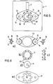
- FIGS. 6 a to 6 e show individual components from which the current generator according to FIG. 5 consists.
- the element 1 shown in FIG. 1 has the outer shape of a commercially available 3.5 "diskette.
- the opening assigned to the read / write head in the associated diskette station is denoted by 2.
- the interface 3 via which data is transferred between the processor 4 and the read / write head in a commercially available diskette station.
- a memory and a driver are designated 5 and 6, respectively.
- a hub 9 which corresponds in shape and design to the hub of a commercially available 3.5 "diskette and is equipped with the required engagement openings.
- An annular magnet 11 surrounds the hub 9 and is from the outside Attached to it, for example glued This ring magnet 11 is magnetized in sections in the axial direction, not shown in detail in FIG.
- a coil 13 with a coil core 14 and winding 15 is part of the stator 12.
- the coil axis is parallel to the axis of rotation of the rotor 8.
- two cover plates 16, 17 are provided which lie against the two end faces of the coil 13 from the outside and recessed in the area of the ring magnet 11 semicircular and tooth-shaped are trained.
- the radially inwardly extending teeth 18 are located above and below the rotating ring magnet 11.
- the teeth 18 are expediently arranged in such a way that a tooth 18 of the one sheet is opposed to a tooth of the other sheet or that a tooth 18 of the one sheet is opposite a tooth of the other sheet is slightly offset.
- the current generated in the winding 15 of the coil 13 during the rotation of the rotor or rotor 8 is fed to a current regulator 20.
- the output of the controller 20 is connected to the circuits to be supplied.
- Components, for example memories, which require a voltage even when the element is removed from the diskette station, can be supplied with the aid of the battery 21.
- the exemplary embodiment according to FIGS. 3 and 4 differs from the exemplary embodiment according to FIGS. 1 and 2 in that the stator 12 comprises two coils 13.
- the cover plates 16, 17 abut the end faces of both coils 13. They demonstrate circular openings with radial internally directed teeth 18.
- a total of eight teeth 18 are provided on each side. This number corresponds to the number of alternately radially magnetized sections of the ring magnet 11. Further exemplary embodiments with more than two coils 13 and / or with different numbers of poles (4, 16, 32, etc.) are possible.
- FIGS. 5 and 6 show in detail the structure of a current generator according to an embodiment of the invention.
- the upper cover plate (stator plate 16) lying against the end faces of the coils 13 is oval.
- the coil cores 14 are guided therein.
- a spacer 23 holds the coils 13, which are also shown in section in FIG. 6a, in the desired position.
- the magnetic ring 11 attached to the hub 9 (FIG. 6d) is magnetized in sections in the axial direction.
- the changing north and south poles are designated N and S in FIGS. 6b (top view) and 6c (side view).
- the magnetic ring 11 can also be composed of sections magnetized in the manner described (glued, etc.).
- the underside of the stator 12 forms the cover plate 17 (FIG. 6e).
- the coils 13 are replaced by a torodial coil 22. This directly surrounds the ring magnet 11. It is wound such that its winding axis surrounds the ring magnet 11 concentrically.
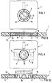
- the exemplary embodiment according to FIGS. 9 and 10 comprises stator laminations 16, 17 with different tooth designs compared to the previously described examples.
- the teeth 18 are bent inwards by approximately 90 ° with respect to the plane of the element 1 in such a way that a tooth 18 of the other stator plate 17 or 16 engages in the tooth gap of the one stator plate 16 or 17.
- the teeth 18 include the magnetic ring 11, which is magnetized in the radial direction (cf. side view in FIG. 10).
- the advantage of this solution is, inter alia, that a magnetic ring 11 with a maximum height, which corresponds approximately to the height of the element 1, can be used.
- the generators described supply currents that are sufficient to supply integrated circuits.
- magnets made of materials with a high coercive field strength for example nickel-iron-boron magnets, welded or sintered, is expedient.
- the generator can also be used in elements 1 which have the outer shape of a cassette.
Landscapes
- Engineering & Computer Science (AREA)
- Power Engineering (AREA)
- Physics & Mathematics (AREA)
- Theoretical Computer Science (AREA)
- General Physics & Mathematics (AREA)
- Computer Hardware Design (AREA)
- Microelectronics & Electronic Packaging (AREA)
- Computer Networks & Wireless Communication (AREA)
- Artificial Intelligence (AREA)
- Computer Vision & Pattern Recognition (AREA)
- Permanent Magnet Type Synchronous Machine (AREA)
- Communication Control (AREA)
- Permanent Field Magnets Of Synchronous Machinery (AREA)
Applications Claiming Priority (3)
| Application Number | Priority Date | Filing Date | Title |
|---|---|---|---|
| DE4122170 | 1991-07-04 | ||
| DE4122170A DE4122170A1 (de) | 1991-07-04 | 1991-07-04 | In edv-einrichtungen einsteckbares element |
| PCT/EP1992/001357 WO1993001643A1 (de) | 1991-07-04 | 1992-06-16 | In edv-einrichtungen einsteckbares element |
Publications (2)
| Publication Number | Publication Date |
|---|---|
| EP0592468A1 EP0592468A1 (de) | 1994-04-20 |
| EP0592468B1 true EP0592468B1 (de) | 1996-05-22 |
Family
ID=6435436
Family Applications (1)
| Application Number | Title | Priority Date | Filing Date |
|---|---|---|---|
| EP92911940A Expired - Lifetime EP0592468B1 (de) | 1991-07-04 | 1992-06-16 | In edv-einrichtungen einsteckbares element |
Country Status (7)
| Country | Link |
|---|---|
| EP (1) | EP0592468B1 (cg-RX-API-DMAC7.html) |
| JP (1) | JPH07500238A (cg-RX-API-DMAC7.html) |
| AT (1) | ATE138510T1 (cg-RX-API-DMAC7.html) |
| AU (1) | AU1999992A (cg-RX-API-DMAC7.html) |
| CA (1) | CA2112687A1 (cg-RX-API-DMAC7.html) |
| DE (1) | DE4122170A1 (cg-RX-API-DMAC7.html) |
| WO (1) | WO1993001643A1 (cg-RX-API-DMAC7.html) |
Families Citing this family (8)
| Publication number | Priority date | Publication date | Assignee | Title |
|---|---|---|---|---|
| EP0892535A1 (en) * | 1997-07-18 | 1999-01-20 | Ching-Yuan Wang | Cassette arrangement for handsfree use of a mobile telephone in an automobile |
| EP0978930A1 (en) * | 1998-08-07 | 2000-02-09 | Hitachi Metals, Ltd. | Permanent magnet generator for use in a diskette, and diskette incorporating such generator |
| JP3718069B2 (ja) | 1998-11-27 | 2005-11-16 | 株式会社Neomax | 永久磁石式発電機およびそれを持ったディスケット |
| EP1005140A2 (en) | 1998-11-27 | 2000-05-31 | Hitachi Metals, Ltd. | Diskette incorporating permanent magnet generator with low leakage flux |
| JP2001095214A (ja) | 1999-07-16 | 2001-04-06 | Hitachi Metals Ltd | 永久磁石式発電機を組み込んだディスケット |
| EP1113438A3 (de) * | 1999-12-30 | 2002-04-10 | AM3 AutoMotive MultiMedia AG | Medium für einen Media-Player |
| JP3936538B2 (ja) * | 2000-05-30 | 2007-06-27 | 株式会社Neomax | 薄型永久磁石式発電機及びそれを組み込んだディスケット |
| US6316912B1 (en) * | 2000-07-27 | 2001-11-13 | Philips Electronics North America Corp. | Power generating device having a form factor suitable for insertion into a player device |
Family Cites Families (3)
| Publication number | Priority date | Publication date | Assignee | Title |
|---|---|---|---|---|
| US2638557A (en) * | 1949-07-20 | 1953-05-12 | Longert Christian Leo | Wheel hub with built-in dynamos, especially for bicycles and motor bicycles |
| US4562399A (en) * | 1983-06-14 | 1985-12-31 | Kollmorgen Technologies Corporation | Brushless DC tachometer |
| DE3903454A1 (de) * | 1988-12-12 | 1990-06-13 | Raymund H Eisele | In edv-einrichtungen einsteckbares element |
-
1991
- 1991-07-04 DE DE4122170A patent/DE4122170A1/de active Granted
-
1992
- 1992-06-16 EP EP92911940A patent/EP0592468B1/de not_active Expired - Lifetime
- 1992-06-16 AU AU19999/92A patent/AU1999992A/en not_active Abandoned
- 1992-06-16 CA CA002112687A patent/CA2112687A1/en not_active Abandoned
- 1992-06-16 AT AT92911940T patent/ATE138510T1/de not_active IP Right Cessation
- 1992-06-16 JP JP5501909A patent/JPH07500238A/ja active Pending
- 1992-06-16 WO PCT/EP1992/001357 patent/WO1993001643A1/de not_active Ceased
Also Published As
| Publication number | Publication date |
|---|---|
| DE4122170A1 (de) | 1993-01-07 |
| ATE138510T1 (de) | 1996-06-15 |
| WO1993001643A1 (de) | 1993-01-21 |
| JPH07500238A (ja) | 1995-01-05 |
| EP0592468A1 (de) | 1994-04-20 |
| DE4122170C2 (cg-RX-API-DMAC7.html) | 1993-07-01 |
| AU1999992A (en) | 1993-02-11 |
| CA2112687A1 (en) | 1993-01-21 |
Similar Documents
| Publication | Publication Date | Title |
|---|---|---|
| DE69605449T2 (de) | Basiselement für scheibenformige elektrische Maschine und entsprechende elektrische Maschine | |
| DE60217978T2 (de) | Rotierende elektrische Maschine | |
| EP0691727B1 (de) | Mittels Permanentmagneten erregbarer elektrischer Motor, insbesondere Innenläufer- oder Aussenläufermotor | |
| DE68914841T2 (de) | Elektrischer motor. | |
| DE2840562C2 (de) | Elektromotor | |
| DE2559838C2 (de) | Elektromotor mit Vorrichtung zur Erzeugung von Drehzahlsignalen | |
| DE2918493A1 (de) | Buerstenloser gedruckter gleichstrommotor | |
| DE2748543A1 (de) | Buerstenloser gleichstrommotor | |
| EP0592468B1 (de) | In edv-einrichtungen einsteckbares element | |
| DE1538976A1 (de) | Elektromotor | |
| DE3729522A1 (de) | Flacher elektromotor | |
| DE69402797T2 (de) | Linearer Schrittmotor | |
| DE2949979C2 (de) | Antriebsvorrichtung für eine Bandteller-Nabe zum Ab- oder Aufwickeln eines bandförmigen Aufzeichnungsträgers | |
| EP0788779B1 (de) | Gleichstrommotor zum Antrieb eines dentalen Instrumentes | |
| DE1488006A1 (de) | Schrittmotor | |
| DE1638216A1 (de) | Buerstenloser Gleichstrommotor | |
| DE3217283C2 (cg-RX-API-DMAC7.html) | ||
| DE3213263C2 (de) | Einphasenschrittmotor | |
| DE2938771A1 (de) | Elektrisch-mechanischer wandler | |
| DE3546933B4 (de) | Festplattenspeicher | |
| DE2832165C2 (de) | Reluktanzgenerator | |
| DE69016622T2 (de) | Spindelmotor und damit ausgestatteter Diskantrieb. | |
| EP0405258B1 (de) | Rotatorische elektrische Maschine | |
| DE4409993A1 (de) | Elektrische Antriebsvorrichtung in Form eines Axialfeldmotors mit Magnet-Gaslagerung | |
| DE2733741C3 (de) | Drehmomentenerzeuger für Kreiselgeräte |
Legal Events
| Date | Code | Title | Description |
|---|---|---|---|
| PUAI | Public reference made under article 153(3) epc to a published international application that has entered the european phase |
Free format text: ORIGINAL CODE: 0009012 |
|
| 17P | Request for examination filed |
Effective date: 19931224 |
|
| AK | Designated contracting states |
Kind code of ref document: A1 Designated state(s): AT BE CH DK ES FR GB IT LI NL SE |
|
| 17Q | First examination report despatched |
Effective date: 19950117 |
|
| GRAH | Despatch of communication of intention to grant a patent |
Free format text: ORIGINAL CODE: EPIDOS IGRA |
|
| GRAA | (expected) grant |
Free format text: ORIGINAL CODE: 0009210 |
|
| AK | Designated contracting states |
Kind code of ref document: B1 Designated state(s): AT BE CH DK ES FR GB IT LI NL SE |
|
| PG25 | Lapsed in a contracting state [announced via postgrant information from national office to epo] |
Ref country code: NL Free format text: LAPSE BECAUSE OF FAILURE TO SUBMIT A TRANSLATION OF THE DESCRIPTION OR TO PAY THE FEE WITHIN THE PRESCRIBED TIME-LIMIT Effective date: 19960522 Ref country code: IT Free format text: LAPSE BECAUSE OF FAILURE TO SUBMIT A TRANSLATION OF THE DESCRIPTION OR TO PAY THE FEE WITHIN THE PRE;WARNING: LAPSES OF ITALIAN PATENTS WITH EFFECTIVE DATE BEFORE 2007 MAY HAVE OCCURRED AT ANY TIME BEFORE 2007. THE CORRECT EFFECTIVE DATE MAY BE DIFFERENT FROM THE ONE RECORDED.SCRIBED TIME-LIMIT Effective date: 19960522 Ref country code: GB Effective date: 19960522 Ref country code: FR Effective date: 19960522 Ref country code: ES Free format text: THE PATENT HAS BEEN ANNULLED BY A DECISION OF A NATIONAL AUTHORITY Effective date: 19960522 Ref country code: DK Effective date: 19960522 Ref country code: BE Effective date: 19960522 |
|
| REF | Corresponds to: |
Ref document number: 138510 Country of ref document: AT Date of ref document: 19960615 Kind code of ref document: T |
|
| PG25 | Lapsed in a contracting state [announced via postgrant information from national office to epo] |
Ref country code: AT Effective date: 19960616 |
|
| PG25 | Lapsed in a contracting state [announced via postgrant information from national office to epo] |
Ref country code: LI Effective date: 19960630 Ref country code: CH Effective date: 19960630 |
|
| PG25 | Lapsed in a contracting state [announced via postgrant information from national office to epo] |
Ref country code: SE Effective date: 19960822 |
|
| EN | Fr: translation not filed | ||
| EN | Fr: translation not filed | ||
| NLV1 | Nl: lapsed or annulled due to failure to fulfill the requirements of art. 29p and 29m of the patents act | ||
| GBV | Gb: ep patent (uk) treated as always having been void in accordance with gb section 77(7)/1977 [no translation filed] |
Effective date: 19960522 |
|
| REG | Reference to a national code |
Ref country code: CH Ref legal event code: PL |
|
| PLBE | No opposition filed within time limit |
Free format text: ORIGINAL CODE: 0009261 |
|
| STAA | Information on the status of an ep patent application or granted ep patent |
Free format text: STATUS: NO OPPOSITION FILED WITHIN TIME LIMIT |
|
| 26N | No opposition filed |