EP0591797A1 - Mechanischer Sensor - Google Patents
Mechanischer Sensor Download PDFInfo
- Publication number
- EP0591797A1 EP0591797A1 EP93115516A EP93115516A EP0591797A1 EP 0591797 A1 EP0591797 A1 EP 0591797A1 EP 93115516 A EP93115516 A EP 93115516A EP 93115516 A EP93115516 A EP 93115516A EP 0591797 A1 EP0591797 A1 EP 0591797A1
- Authority
- EP
- European Patent Office
- Prior art keywords
- inertial body
- trigger means
- trigger
- mechanical sensor
- firing pin
- Prior art date
- Legal status (The legal status is an assumption and is not a legal conclusion. Google has not performed a legal analysis and makes no representation as to the accuracy of the status listed.)
- Granted
Links
Images


Classifications
-
- B—PERFORMING OPERATIONS; TRANSPORTING
- B60—VEHICLES IN GENERAL
- B60R—VEHICLES, VEHICLE FITTINGS, OR VEHICLE PARTS, NOT OTHERWISE PROVIDED FOR
- B60R21/00—Arrangements or fittings on vehicles for protecting or preventing injuries to occupants or pedestrians in case of accidents or other traffic risks
- B60R21/02—Occupant safety arrangements or fittings, e.g. crash pads
- B60R21/16—Inflatable occupant restraints or confinements designed to inflate upon impact or impending impact, e.g. air bags
- B60R21/33—Arrangements for non-electric triggering of inflation
-
- F—MECHANICAL ENGINEERING; LIGHTING; HEATING; WEAPONS; BLASTING
- F42—AMMUNITION; BLASTING
- F42C—AMMUNITION FUZES; ARMING OR SAFETY MEANS THEREFOR
- F42C1/00—Impact fuzes, i.e. fuzes actuated only by ammunition impact
- F42C1/02—Impact fuzes, i.e. fuzes actuated only by ammunition impact with firing-pin structurally combined with fuze
- F42C1/04—Impact fuzes, i.e. fuzes actuated only by ammunition impact with firing-pin structurally combined with fuze operating by inertia of members on impact
-
- G—PHYSICS
- G01—MEASURING; TESTING
- G01P—MEASURING LINEAR OR ANGULAR SPEED, ACCELERATION, DECELERATION, OR SHOCK; INDICATING PRESENCE, ABSENCE, OR DIRECTION, OF MOVEMENT
- G01P15/00—Measuring acceleration; Measuring deceleration; Measuring shock, i.e. sudden change of acceleration
- G01P15/02—Measuring acceleration; Measuring deceleration; Measuring shock, i.e. sudden change of acceleration by making use of inertia forces using solid seismic masses
- G01P15/03—Measuring acceleration; Measuring deceleration; Measuring shock, i.e. sudden change of acceleration by making use of inertia forces using solid seismic masses by using non-electrical means
- G01P15/032—Measuring acceleration; Measuring deceleration; Measuring shock, i.e. sudden change of acceleration by making use of inertia forces using solid seismic masses by using non-electrical means by measuring the displacement of a movable inertial mass
- G01P15/036—Measuring acceleration; Measuring deceleration; Measuring shock, i.e. sudden change of acceleration by making use of inertia forces using solid seismic masses by using non-electrical means by measuring the displacement of a movable inertial mass for indicating predetermined acceleration values
Definitions
- the present invention relates to a mechanical sensor for sensing a sudden deceleration of a vehicle.
- the pretensioner retracts the webbing which a passenger is wearing by a predetermined amount so as to forcefully take up slack in the webbing thereby improving the restraint of the passenger.
- a pretensioner of the type that pulls the buckle to tension the webbing for example, is equipped with a gas generator having a mechanical igniting sensor.
- the gas generator which is provided with a cylinder, is connected to a buckle via a wire or the like.
- the mechanical igniting sensor senses the deceleration so as to activate the gas generator.
- the instantaneous generation of gas moves the cylinder so that the force of the movement is transmitted to the buckle via the wire so as to tension the webbing.
- the mechanical igniting sensor employed in a pretensioner of this prior art is basically composed of an ignition pin that fires a detonator, an inertial body that is moved inertially due to a large acceleration, a trigger member such as a ball that is present between the ignition pin and the inertial body so as to restrain the ignition pin from moving.
- a trigger member such as a ball that is present between the ignition pin and the inertial body so as to restrain the ignition pin from moving.
- the frictional force between the trigger member and the inertial body changes greatly during the movement of the inertial body. Because of these factors, the sensitivity of the operation is not steady, and a stable sensor operation is difficult to obtain.
- the pressure on the trigger member coming from the ignition pin can be amplified because of the change in the direction of the pressure. In such cases, the amplified pressure given to the inertial body increases the frictional force between the trigger member and the inertial body. As a result, it causes the dispersion of sensitivity and the loss of operation stability.
- the pressing forces on the trigger member of the mechanical igniting sensor in the prior art tend to counteract each other. It is therefore possible that the trigger member will fail to move as it should or stall even under a predetermined inertial force.
- Another object of the present invention is to provide a mechanical sensor having a simple structure that can be reset easily after a test operation of sensitivity and the like without sacrificing stability of operation.
- the mechanical sensor of the present invention is structured such that when the inertial body moves, the inertial body and the trigger lever move relative to each other while maintaining linear contact.
- the trigger lever when the slide holding portion of the trigger lever is separated and released from the inertial mass body, the trigger lever is freed so as to rotate about its supporting shaft.
- the ignition pin that is urged by a firing spring rotates the trigger lever in a direction so as to separate the trigger lever from the ignition pin. This releases the ignition pin from engagement with the engaging portion of the trigger lever.
- the ignition pin then is moved by the urging force of the firing spring in the axial direction to fire the detonator.
- the inertial mass body moves in its linear contact with the slide holding portion of the trigger lever.
- friction between the trigger lever (slide holding portion) and the inertial mass body remains constant, thus contributing to the stable sensitivity of the mechanical ignition sensor during operation.
- friction between the slide holding portion and the inertial mass body can be easily reduced to increase the effects of the trigger lever if the lever ratios between the supporting shaft and the slide holding portion, and the supporting shaft and the engaging portion are set properly.
- the mechanical sensor of the present invention is able to insure stable operation by reducing the unwanted effects of friction between the trigger lever and the inertial mass body without increasing the mass of the inertial body.
- Various means of moving the trigger device can be adopted so that the trigger means remains unmoving until the inertial body has moved a predetermined amount.
- the intertial body will move quickly and sharply once the inertial body has moved the predetermined amount.
- the measures that may be used for this purpose include the formation of a block-like portion on the inertial body and/or the trigger means where the two come into contact with each other, and the formation of a step or edge in which the inertial body, toward the end of its movement, will suddenly separate from the trigger means.
- a spring can urge the inertial mass body in a direction so as to enter the locus of movement of the trigger lever. In this manner, the inertial body will impart a force to the trigger lever so as to engage the firing pin. In this setting, the resistance of the firing pin toward the initial position will engage the pin with the trigger lever and reset the unit.
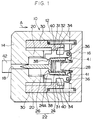
- Figure 1 is a cross sectional view illustrating the initial state of a mechanical sensor according to a first embodiment of the present invention.
- Figure 2 is a cross sectional view illustrating the state of the mechanical sensor after having finished operation in accordance with the first embodiment of the present invention.
- Figure 3 is a cross sectional view illustrating the initial state of a mechanical sensor according to a second embodiment of the present invention.
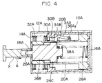
- Figure 4 is a cross sectional view illustrating the state of the mechanical sensor after having finished operation in accordance with the second embodiment of the present invention.
- Figures 1 and 2 show cross sectional views of a mechanical igniting sensor 10 of the present invention.
- the mechanical igniting sensor 10 has a case 12.
- the case 12 is shaped as a cylinder having a bottom wall 14 at one end.
- the open side of the case 12 is sealed by a plate 16.
- a hole 18 penetrates axially therethrough.
- a guide 20 which is of a substantually cylindrical shape, is formed coaxially so as to protrude toward the inner direction of the case 12.
- the ignition pin 22 is composed of a main body 24 which is substantually cylindrical in form, and a projecting portion 26, that is intearally formed with the bottom wall 24A of the main body 24.
- the outside diameter of the main body 24 corresponds to the inside diameter of the guide 20.
- the main body 24 is slidable within the guide 20 along an axial line in the case 12. As indicated in Figure 2, when the ignition pin 22 (main body 24) has moved toward the bottom wall 14 of the case 12 as far as it can go, the projecting portion 26 projects out of the penetration hole 18 that is formed in the bottom wall 14.
- a firing spring 28 which is provided between ignition pin 22 and the plate 16, normally urges the ignition pin 22 in the direction of the penetration hole 18.
- the inertial mass 30 which is substantually in a cylindrical shape, is accomodated between the surrounding walls of the case 12 and the guide 20 so as to be movable.
- a biasing spring 32 are placed between the inertial mass 30 and the plate 16 so as to constantly urge the inertial mass 30 against the bottom wall 14.
- each trigger lever 34 Arranged between the inertial mass 30 and the ignition pin 22 are a pair of trigger levers 34. An end portion of each trigger lever 34 is rotatably supported to a shaft 36. The other end of the trigger lever 34 is bent toward the ignition pin 22 to form an engaging portion 38 so as to be engagable with the ignition pin 22. In other words, the trigger lever 34 rotates around the shaft 36 in such a way that the engaging portion 38 can move toward or away from the ignition pin 22. In a state in which the engaging portion 38 of the trigger lever 34 has engaged the main body 24 of the ignition pin 22 as indicated in Figure 1, the ignition pin 22, under the urging of the firing spring 28, is held in a position in which its projected portion 26 is drawn out of the penetration hole 18.
- a slide holding section 40 projects toward the inertial mass 30.
- the slide holding section 40 corresponds to a sliding portion 31 formed on the inertial mass 30, and is structured so that it will remain in linear contact with the sliding section 31.
- the inertial mass 30 is urged by the bias spring 32 against the bottom-most part of bottom wall 14 of case 12.
- the sliding portion 31 of the inertial mass 30 is contact with the slide holding section 40 of trigger lever 34.
- the engaging portion 38 of the trigger lever 34 is engaged with the main body 24 of the ignition pin 22, and holds the projecting portion 26 of the ignition pin 22 in a position that is drawn out from the penetration hole 18. Further, when the inertial mass 30 moves so as to be separated from the bottom wall 14, the sliding section 31 of the inertial mass 30 and the slide holding portion 40 of the trigger lever 34 maintains linear contact while moving relative to each other.
- the slide portion 31 may be brought into contact with the slide holding portion 40 on the surface of a semicircular arc which has its center on an axis that is parallel to the axial line of the ignition pin 22.
- the slide holding portion 40 may also have a similar arc surface where it makes contact with the slide section 31.
- a pressing projection 41 is provided, which faces the ignition pin 22.
- the sizes and other specifications of the pressing projection 41 have been determined so that the projection 41 can enter the locus of movement of the ignition pin 22 and engage the rear end thereof once the trigger lever 34 has rotated and released the hold of the engaging portion 38 on the ignition pin 22. With this, the sliding of the ignition pin 22 away from the penetration hole 18 can cause the rear end of the ignition pin 22 to press the projection 41.
- the mechanical igniting sensor 10 with the above-described structure is assembled to, for example, a gas generator used with a pretensioner (not illustrated).
- the gas generator contains a gas-generating agent.
- the detonator 42 is located on the axial line of the mechanical ignition sensor 10. In this state, the penetration hole 18 in the case 12 faces the detonator 42, so that the projecting portion 26 of the ignition pin 22 can project through the penetration hole 18, and strike the detonator 42.
- the ignition pin 22 is in the position shown in Figure 1. That is, the ignition pin 22 is separated from the detonator 42 against the bias force of the firing spring 28 (in a position drawn out of the penetration hole 18 in the case 12). In this position, the engaging portion 38 of the trigger lever 34 is engaged with the main body 24 of the ignition pin 22, thus holding the ignition pin 22 from moving.
- the inertial mass 30, pressed by the bias spring 32 has come to the bottom-most part of the bottom wall 14, that is, in the locus of the rotation of the trigger lever 34.
- the slide portion 31, coming into contact with the slide holding portion 40 of the trigger lever 34 prevents the trigger lever 34 from rotating, thereby keeping hold on the ignition pin.
- the inertial mass 30 Inertially moves in the direction of an arrow A, and separates from the rotation locus of the trigger lever 34.
- the inertial mass 30 moves while maintaining linear contact with the slide holding section 40 of the trigger lever 34.
- the trigger lever 34 is the rotatable around shaft 36.
- the ignition pin 22 presses the trigger lever 34 in such a direction that the trigger lever 34 will be rotated and separated from the ignition pin 22.
- the engaging portion 38 of the trigger lever 34 is then disengaged from the main body 24 of the ignition pin 22, thereby releasing the holding of the ignition pin 22.
- the ignition pin 22, under the urging of the firing spring 28 moves in the axial direction, causing the projecting portion 26 to protrude through the penetration hole 18 (see Figure 2).
- the frictional force between the trigger lever 34 (slide holding portion 40) and the inertial mass 30 (slide portion 31) is constant and without fluctuations because the slide portion 31 moves while maintaining linear contact with the slide holding portion 40 of the trigger lever 34.
- the direction in which the ignition pin 22 pushes the trigger lever 34 and the direction in which the trigger lever 34 presses the inertial mass 30 do not vary as they do in the prior art. Accordingly, the frictional force between the trigger lever 34 (slide holding portion 40) and the inertial mass 30 (slide portion 31) does not markedly change as the inertial mass 30 moves. As a result, the sensitivity of the mechanical ignition sensor 10 is stabilized.
- the suitable setting of the trigger lever 34, as to the lever ratios between the shaft 36 and the slide holding portion 40, and the shaft 36 and the engaging portion 38 will enhance the effects of the sensor by reducing the frictional force between the aforementioned trigger lever 34 (slide holding portion 40) and the inertial mass 30 (slide portion 31). For example, by bringing the slide holding portion 40 closer to the shaft 36, such enhanced effectiveness can be expected.
- the pressing projection 41 of the trigger lever 34 has entered the locus of movement of the ignition pin 22 facing to the rear end of the ignition pin 22, so as to be ready to engage therewith.
- the ignition pin 22 can be moved in the axial direction against the urging force of the firing spring 28.
- the projecting portion of the ignition pin 22, which projects out of the penetration hole 18, is pressed in the direction of the plate 16 from the outside of the case 12 using a jig or the like.
- the ignition pin 22 presses the pressing projection 41 of the trigger lever 34, which has entered the locus of movement of the ignition pin 22.
- the trigger lever 34 is rotated about the shaft 36 in such a manner that the engaging section 38 approaches the ignition pin 22.
- the engaging portion 38 reengages the ignition pin 22 (bottom wall 24A of the main body 24) and holds the ignition pin 22 in its initial position which is away from the detonator 42.
- the inertial mass 30, which is pressed by the bias spring 32, reenters the locus of the rotation of the trigger lever 34 so as to stop the rotation and initiate the ignition pin-holding state.
- the mechanical ignition sensor 10 assures stable operation by decreasing the unwanted effects of the frictional force between the trigger lever 34 and the inertial mass 30.
- the trigger lever 34 is rotated to return to its initial position in which the ignition pin 22 is held. Accordingly, the mechanical ignition sensor 10 having undergone an operation test before it is assembled with a gas generator may thereafter be assembled with the gas generator and easily reset to the operative state.
- a flange portion 24C is formed on the ignition pin main body 24B at the end opposite the projecting portion 26A.
- the flange portion 24C is larger in diameter than the other part of the firing pin main body 24A.
- the flange portion 24C engages the L-shaped distal end portion of the trigger lever 34A.
- the L-shape portion serves as the engaging portion 38A, via a through hole 20B of the cylindrical guide 20A.
- a small diameter step portion 30B of the inertial mass 30A is provided on the side of the trigger lever 34A that is opposite to the side of the engaging section 38A.
- the small diameter step portion 30B is in contact with the trigger lever 34A on the other side of the engaging section 38A and thus maintains the engagement of the trigger lever 34A with the ignition pin main body 24B.
- the inertial mass 30A of this embodiment is also pressed by the bias spring 32A. However, the direction in which the inertial mass 30A is pressed is opposite to the direction in which the inertial mass 30 in the first embodiment was pressed (opposite direction indicated by arrow A). The inertial mass 30A of this embodiment is biased in the direction opposite to the biasing direction of the ignition pin.
- a chamfer-shaped sloped surface 34B is formed so that the sloped surface 34B corresponds to the small diameter step portion 30B.
- An acceleration sensor 10A with a structure like that described above may be assembled with a gas generator 50 for use as a pretensioner, for example.
- a gas-generating agent 54 is accomodated inside a cylindracal shaped main body 52 of the gas generator 50 .
- a detonator 56 that will cause the ignition and combustion of the gas-generating agent 54 is also in the main body 52.
- a detonator 56 is located in the axial center portion of the main body 52.
- the acceleration sensor 10A faces the detonator 56.
- a shielding ring 58 is provided between the acceleration sensor 10A and the detonator 56. The sensor is then sealed and secured by a plate 60.
- the penetration hole 16 in the sensor cover 12 faces the detonator 56, and the projecting portion 26 of the ignition pin can protrude through the penetration hole 16 so as to strike the detonator 56.
- FIG. 3 represents the state of the sensor 10A during the normal operation of the vehicle. In this state the ignition pin main body 24B is held by the trigger lever 34A.
- the inertial mass 30A moves in the direction of arrow A, against the urging force of the bias spring 32A.
- the restrictions imposed on the trigger lever 34A are released by the inertial mass 30A.
- the trigger lever 34A is now free to rotate.
- the ignition pin main body 24B is moved in the direction of arrow B by the urging force of the firing spring 28A, and strikes and ignites the detonator 56.
- the resultant ignition and combustion of the gas-generating agent 54 in the gas generator 50 activate the pretensioner.
- the step portion 30B of the inertial mass 30A is in contact with the sloped surface 34B. It is therefore possible to reset the ignition pin by moving the pin in the axial direction against the urging force of the firing spring 28A.
- the ignition pin main body 24B with its projecting portion 26A protruding from the penetration hole 18A is pressed by jig X from outside of the sensor case 12A so as to move jig X into the guide 20A (in the direction of arrow A in Figure 4).
- This causes the step portion 30B of the mass body 30A which is pressed by the bias spring 32A to press the trigger lever 34A in the direction of the ignition pin main body 24B via its sloped surface 34B.
- the ignition pin main body 24B moves to the initial position.
- the engaging section 38A of the trigger lever 34A engages the flange 24B of the ignition pin main body 24B, holds the ignition pin main body 24B in the initial position, and reset the sensor 10A.
- the slope of the sloped surface 34B may be a curved surface instead of a straight sloped surface in the figure.
- the radius of curvature of the curved surface may be selected arbitrarily.
- the sloped surface 34B does not necessarily have to be provided on the trigger lever 34A. It may be provided on the inertial mass 30A, as long as it is a sloped surface that can transmit via the inertial mass 30A the force of the bias spring 32A as the force that returns the trigger lever 34A.
- the firing pin 22 was held by a pair of the trigger lever 34.
- the number of trigger levers is not limited. There may be one or three or more levers 34.
- the previously described mechanical ignition sensors used a gas generator type pretensioner.
- the application of the sensors are not restricted to this use. It is possible to apply these sensors to other systems that will act upon the impact of a firing pin such as an air bag system that will inflate a bag in front of a passenger during an emergency of the vehicle.
Landscapes
- Engineering & Computer Science (AREA)
- General Engineering & Computer Science (AREA)
- Mechanical Engineering (AREA)
- Physics & Mathematics (AREA)
- General Physics & Mathematics (AREA)
- Air Bags (AREA)
- Automotive Seat Belt Assembly (AREA)
Applications Claiming Priority (6)
| Application Number | Priority Date | Filing Date | Title |
|---|---|---|---|
| JP67428/92U | 1992-09-28 | ||
| JP6742892U JPH0643573U (ja) | 1992-09-28 | 1992-09-28 | 加速度センサ |
| JP1993047407U JP2590493Y2 (ja) | 1993-08-31 | 1993-08-31 | 機械着火式センサ |
| JP1993047331U JP2590492Y2 (ja) | 1993-08-31 | 1993-08-31 | 機械着火式センサ |
| JP47407/93U | 1993-08-31 | ||
| JP47331/93U | 1993-08-31 |
Publications (2)
| Publication Number | Publication Date |
|---|---|
| EP0591797A1 true EP0591797A1 (de) | 1994-04-13 |
| EP0591797B1 EP0591797B1 (de) | 1997-12-03 |
Family
ID=27292942
Family Applications (1)
| Application Number | Title | Priority Date | Filing Date |
|---|---|---|---|
| EP93115516A Expired - Lifetime EP0591797B1 (de) | 1992-09-28 | 1993-09-25 | Mechanischer Sensor |
Country Status (3)
| Country | Link |
|---|---|
| US (1) | US5386774A (de) |
| EP (1) | EP0591797B1 (de) |
| DE (1) | DE69315529T2 (de) |
Cited By (5)
| Publication number | Priority date | Publication date | Assignee | Title |
|---|---|---|---|---|
| EP0642958A1 (de) * | 1993-09-09 | 1995-03-15 | Kabushiki Kaisha Tokai-Rika-Denki-Seisakusho | Ansteuermechanismus einer Kraftfahrzeug-Sicherheitseinrichtung |
| EP0679557A1 (de) * | 1994-04-22 | 1995-11-02 | Kabushiki Kaisha Tokai-Rika-Denki-Seisakusho | Beschleunigungsmessaufnehmer |
| EP0686535A1 (de) * | 1994-06-07 | 1995-12-13 | TRW Occupant Restraint Systems GmbH | Sensor zur fahrzeugsensitiven Auslösung eines Zünders |
| EP0688704A1 (de) * | 1994-06-21 | 1995-12-27 | Kabushiki Kaisha Tokai-Rika-Denki-Seisakusho | Mechanischer Beschleunigungssensor und Ansteuermechanismus eines Fahrzeugsicherheitssystems |
| EP0695673A3 (de) * | 1994-08-01 | 1997-12-17 | Kabushiki Kaisha Tokai-Rika-Denki-Seisakusho | Mechanischer Zündungs-Sensor |
Families Citing this family (2)
| Publication number | Priority date | Publication date | Assignee | Title |
|---|---|---|---|---|
| KR101317713B1 (ko) | 2011-07-06 | 2013-11-11 | 세주엔지니어링주식회사 | 1,2차 전지 및 비축전지 활성화를 위한 타격장치를 구비하여 전자식 자폭기능을 부여한 신관 |
| KR101358935B1 (ko) * | 2012-10-09 | 2014-02-06 | 세주엔지니어링주식회사 | 내 충격 자폭 신관 |
Citations (3)
| Publication number | Priority date | Publication date | Assignee | Title |
|---|---|---|---|---|
| FR442769A (fr) * | 1911-05-22 | 1912-09-09 | Krupp Ag | Fusée percutante |
| DE3742961A1 (de) * | 1986-12-19 | 1988-07-07 | Honda Motor Co Ltd | Verzoegerungssensor |
| DE3908117A1 (de) * | 1989-03-13 | 1990-09-20 | Bayerische Motoren Werke Ag | Loesbare verbindung, insbesondere fuer eine sicherheitsvorrichtung an einem kraftfahrzeug |
Family Cites Families (3)
| Publication number | Priority date | Publication date | Assignee | Title |
|---|---|---|---|---|
| US3638501A (en) * | 1970-04-27 | 1972-02-01 | Gen Motors Corp | Sensor |
| US4889068A (en) * | 1987-06-09 | 1989-12-26 | Honda Giken Kogyo Kabushiki Kaisha | Deceleration sensor |
| EP0361476B1 (de) * | 1988-09-29 | 1994-04-13 | Honda Giken Kogyo Kabushiki Kaisha | Verzögerungssensor |
-
1993
- 1993-09-24 US US08/125,806 patent/US5386774A/en not_active Expired - Fee Related
- 1993-09-25 DE DE69315529T patent/DE69315529T2/de not_active Expired - Fee Related
- 1993-09-25 EP EP93115516A patent/EP0591797B1/de not_active Expired - Lifetime
Patent Citations (3)
| Publication number | Priority date | Publication date | Assignee | Title |
|---|---|---|---|---|
| FR442769A (fr) * | 1911-05-22 | 1912-09-09 | Krupp Ag | Fusée percutante |
| DE3742961A1 (de) * | 1986-12-19 | 1988-07-07 | Honda Motor Co Ltd | Verzoegerungssensor |
| DE3908117A1 (de) * | 1989-03-13 | 1990-09-20 | Bayerische Motoren Werke Ag | Loesbare verbindung, insbesondere fuer eine sicherheitsvorrichtung an einem kraftfahrzeug |
Cited By (6)
| Publication number | Priority date | Publication date | Assignee | Title |
|---|---|---|---|---|
| EP0642958A1 (de) * | 1993-09-09 | 1995-03-15 | Kabushiki Kaisha Tokai-Rika-Denki-Seisakusho | Ansteuermechanismus einer Kraftfahrzeug-Sicherheitseinrichtung |
| EP0679557A1 (de) * | 1994-04-22 | 1995-11-02 | Kabushiki Kaisha Tokai-Rika-Denki-Seisakusho | Beschleunigungsmessaufnehmer |
| EP0686535A1 (de) * | 1994-06-07 | 1995-12-13 | TRW Occupant Restraint Systems GmbH | Sensor zur fahrzeugsensitiven Auslösung eines Zünders |
| EP0688704A1 (de) * | 1994-06-21 | 1995-12-27 | Kabushiki Kaisha Tokai-Rika-Denki-Seisakusho | Mechanischer Beschleunigungssensor und Ansteuermechanismus eines Fahrzeugsicherheitssystems |
| US5609357A (en) * | 1994-06-21 | 1997-03-11 | Kabushiki Kaisha Tokai-Rika-Denki-Seisakusho | Mechanical ignition sensor |
| EP0695673A3 (de) * | 1994-08-01 | 1997-12-17 | Kabushiki Kaisha Tokai-Rika-Denki-Seisakusho | Mechanischer Zündungs-Sensor |
Also Published As
| Publication number | Publication date |
|---|---|
| DE69315529D1 (de) | 1998-01-15 |
| DE69315529T2 (de) | 1998-04-02 |
| EP0591797B1 (de) | 1997-12-03 |
| US5386774A (en) | 1995-02-07 |
Similar Documents
| Publication | Publication Date | Title |
|---|---|---|
| JPH08525B2 (ja) | 自動車用の安全ベルト抑止装置のための緊張手段 | |
| US5542697A (en) | Trigger mechanism for belt pretensioner | |
| US5386774A (en) | Mechanical sensor | |
| US5564747A (en) | Trigger device | |
| EP0861172B1 (de) | Vorrichtung zum zünden einer pyrotechnischen treibladung | |
| US5415099A (en) | Mechanical ignition sensor | |
| US5286053A (en) | Apparatus for preventing undesired ignition of a pyrotechnic transmission line | |
| US5538284A (en) | Device for controlling acceleration sensor | |
| JP2590492Y2 (ja) | 機械着火式センサ | |
| JP2590493Y2 (ja) | 機械着火式センサ | |
| EP0688704B1 (de) | Mechanischer Beschleunigungssensor und Ansteuermechanismus eines Fahrzeugsicherheitssystems | |
| GB2273647A (en) | Vehicle deceleration sensor for releasing an ignition pin, e.g. in a seat belt pretensioner | |
| JPH0718270U (ja) | 機械着火式センサ | |
| JPH0643573U (ja) | 加速度センサ | |
| US5328204A (en) | Acceleration sensor | |
| JP3431344B2 (ja) | 機械着火式センサ | |
| JPH01240345A (ja) | シートベルト巻込装置 | |
| JPH05458Y2 (de) | ||
| JPH058700A (ja) | シートベルト装置のメカニカルセンサ | |
| JPH0630575Y2 (ja) | 車輌用衝突検知装置 | |
| JPH06222069A (ja) | 機械着火式センサ | |
| JPH02182555A (ja) | 車輌用衝突検知装置 | |
| JPH085363B2 (ja) | 乗員拘束装置のための安全装置 | |
| JPH0718271U (ja) | 機械着火式センサ | |
| JPH07461B2 (ja) | 車輌用加速度検知装置 |
Legal Events
| Date | Code | Title | Description |
|---|---|---|---|
| PUAI | Public reference made under article 153(3) epc to a published international application that has entered the european phase |
Free format text: ORIGINAL CODE: 0009012 |
|
| AK | Designated contracting states |
Kind code of ref document: A1 Designated state(s): DE FR GB |
|
| 17P | Request for examination filed |
Effective date: 19940520 |
|
| 17Q | First examination report despatched |
Effective date: 19950531 |
|
| GRAG | Despatch of communication of intention to grant |
Free format text: ORIGINAL CODE: EPIDOS AGRA |
|
| GRAH | Despatch of communication of intention to grant a patent |
Free format text: ORIGINAL CODE: EPIDOS IGRA |
|
| GRAH | Despatch of communication of intention to grant a patent |
Free format text: ORIGINAL CODE: EPIDOS IGRA |
|
| GRAA | (expected) grant |
Free format text: ORIGINAL CODE: 0009210 |
|
| AK | Designated contracting states |
Kind code of ref document: B1 Designated state(s): DE FR GB |
|
| REF | Corresponds to: |
Ref document number: 69315529 Country of ref document: DE Date of ref document: 19980115 |
|
| ET | Fr: translation filed | ||
| PLBE | No opposition filed within time limit |
Free format text: ORIGINAL CODE: 0009261 |
|
| STAA | Information on the status of an ep patent application or granted ep patent |
Free format text: STATUS: NO OPPOSITION FILED WITHIN TIME LIMIT |
|
| 26N | No opposition filed | ||
| PGFP | Annual fee paid to national office [announced via postgrant information from national office to epo] |
Ref country code: FR Payment date: 20000912 Year of fee payment: 8 |
|
| PGFP | Annual fee paid to national office [announced via postgrant information from national office to epo] |
Ref country code: DE Payment date: 20000918 Year of fee payment: 8 |
|
| PGFP | Annual fee paid to national office [announced via postgrant information from national office to epo] |
Ref country code: GB Payment date: 20000920 Year of fee payment: 8 |
|
| PG25 | Lapsed in a contracting state [announced via postgrant information from national office to epo] |
Ref country code: GB Free format text: LAPSE BECAUSE OF NON-PAYMENT OF DUE FEES Effective date: 20010925 |
|
| REG | Reference to a national code |
Ref country code: GB Ref legal event code: IF02 |
|
| PG25 | Lapsed in a contracting state [announced via postgrant information from national office to epo] |
Ref country code: DE Free format text: LAPSE BECAUSE OF NON-PAYMENT OF DUE FEES Effective date: 20020501 |
|
| GBPC | Gb: european patent ceased through non-payment of renewal fee |
Effective date: 20010925 |
|
| PG25 | Lapsed in a contracting state [announced via postgrant information from national office to epo] |
Ref country code: FR Free format text: LAPSE BECAUSE OF NON-PAYMENT OF DUE FEES Effective date: 20020531 |
|
| REG | Reference to a national code |
Ref country code: FR Ref legal event code: ST |