EP0590171A1 - Wabenkörper zum Reinigen von Abgas, und Verfahren zu seiner Herstellung - Google Patents
Wabenkörper zum Reinigen von Abgas, und Verfahren zu seiner Herstellung Download PDFInfo
- Publication number
- EP0590171A1 EP0590171A1 EP92116499A EP92116499A EP0590171A1 EP 0590171 A1 EP0590171 A1 EP 0590171A1 EP 92116499 A EP92116499 A EP 92116499A EP 92116499 A EP92116499 A EP 92116499A EP 0590171 A1 EP0590171 A1 EP 0590171A1
- Authority
- EP
- European Patent Office
- Prior art keywords
- honeycomb structure
- plate
- flat
- flat plate
- corrugated
- Prior art date
- Legal status (The legal status is an assumption and is not a legal conclusion. Google has not performed a legal analysis and makes no representation as to the accuracy of the status listed.)
- Granted
Links
- 238000004519 manufacturing process Methods 0.000 title claims description 9
- 238000003466 welding Methods 0.000 claims abstract description 10
- 238000005219 brazing Methods 0.000 claims description 26
- 239000011159 matrix material Substances 0.000 claims description 10
- 239000011888 foil Substances 0.000 claims description 6
- 239000012777 electrically insulating material Substances 0.000 claims description 3
- 239000000463 material Substances 0.000 claims description 3
- 229910000808 amorphous metal alloy Inorganic materials 0.000 claims 4
- 229910000831 Steel Inorganic materials 0.000 claims 1
- 239000010959 steel Substances 0.000 claims 1
- 238000001816 cooling Methods 0.000 abstract description 9
- 238000010438 heat treatment Methods 0.000 abstract description 8
- 230000008602 contraction Effects 0.000 abstract description 5
- 238000004299 exfoliation Methods 0.000 abstract description 5
- 239000002184 metal Substances 0.000 description 25
- 229910052751 metal Inorganic materials 0.000 description 25
- 239000000945 filler Substances 0.000 description 23
- 239000007789 gas Substances 0.000 description 15
- 239000003054 catalyst Substances 0.000 description 8
- 230000003197 catalytic effect Effects 0.000 description 4
- 150000002739 metals Chemical class 0.000 description 4
- PXHVJJICTQNCMI-UHFFFAOYSA-N Nickel Chemical group [Ni] PXHVJJICTQNCMI-UHFFFAOYSA-N 0.000 description 3
- 229910001220 stainless steel Inorganic materials 0.000 description 3
- 239000010935 stainless steel Substances 0.000 description 3
- XEEYBQQBJWHFJM-UHFFFAOYSA-N Iron Chemical group [Fe] XEEYBQQBJWHFJM-UHFFFAOYSA-N 0.000 description 2
- 210000004027 cell Anatomy 0.000 description 2
- 210000002421 cell wall Anatomy 0.000 description 2
- 238000010586 diagram Methods 0.000 description 2
- 238000000034 method Methods 0.000 description 2
- 230000001473 noxious effect Effects 0.000 description 2
- 238000003825 pressing Methods 0.000 description 2
- 239000010953 base metal Substances 0.000 description 1
- 230000015572 biosynthetic process Effects 0.000 description 1
- 239000012141 concentrate Substances 0.000 description 1
- 239000012530 fluid Substances 0.000 description 1
- 238000012986 modification Methods 0.000 description 1
- 230000004048 modification Effects 0.000 description 1
- 229910052759 nickel Inorganic materials 0.000 description 1
Images


Classifications
-
- B—PERFORMING OPERATIONS; TRANSPORTING
- B23—MACHINE TOOLS; METAL-WORKING NOT OTHERWISE PROVIDED FOR
- B23K—SOLDERING OR UNSOLDERING; WELDING; CLADDING OR PLATING BY SOLDERING OR WELDING; CUTTING BY APPLYING HEAT LOCALLY, e.g. FLAME CUTTING; WORKING BY LASER BEAM
- B23K1/00—Soldering, e.g. brazing, or unsoldering
- B23K1/0008—Soldering, e.g. brazing, or unsoldering specially adapted for particular articles or work
- B23K1/0014—Brazing of honeycomb sandwich structures
-
- B01J35/56—
-
- F—MECHANICAL ENGINEERING; LIGHTING; HEATING; WEAPONS; BLASTING
- F01—MACHINES OR ENGINES IN GENERAL; ENGINE PLANTS IN GENERAL; STEAM ENGINES
- F01N—GAS-FLOW SILENCERS OR EXHAUST APPARATUS FOR MACHINES OR ENGINES IN GENERAL; GAS-FLOW SILENCERS OR EXHAUST APPARATUS FOR INTERNAL COMBUSTION ENGINES
- F01N3/00—Exhaust or silencing apparatus having means for purifying, rendering innocuous, or otherwise treating exhaust
- F01N3/08—Exhaust or silencing apparatus having means for purifying, rendering innocuous, or otherwise treating exhaust for rendering innocuous
- F01N3/10—Exhaust or silencing apparatus having means for purifying, rendering innocuous, or otherwise treating exhaust for rendering innocuous by thermal or catalytic conversion of noxious components of exhaust
- F01N3/18—Exhaust or silencing apparatus having means for purifying, rendering innocuous, or otherwise treating exhaust for rendering innocuous by thermal or catalytic conversion of noxious components of exhaust characterised by methods of operation; Control
- F01N3/20—Exhaust or silencing apparatus having means for purifying, rendering innocuous, or otherwise treating exhaust for rendering innocuous by thermal or catalytic conversion of noxious components of exhaust characterised by methods of operation; Control specially adapted for catalytic conversion ; Methods of operation or control of catalytic converters
- F01N3/2006—Periodically heating or cooling catalytic reactors, e.g. at cold starting or overheating
- F01N3/2013—Periodically heating or cooling catalytic reactors, e.g. at cold starting or overheating using electric or magnetic heating means
- F01N3/2026—Periodically heating or cooling catalytic reactors, e.g. at cold starting or overheating using electric or magnetic heating means directly electrifying the catalyst substrate, i.e. heating the electrically conductive catalyst substrate by joule effect
-
- F—MECHANICAL ENGINEERING; LIGHTING; HEATING; WEAPONS; BLASTING
- F01—MACHINES OR ENGINES IN GENERAL; ENGINE PLANTS IN GENERAL; STEAM ENGINES
- F01N—GAS-FLOW SILENCERS OR EXHAUST APPARATUS FOR MACHINES OR ENGINES IN GENERAL; GAS-FLOW SILENCERS OR EXHAUST APPARATUS FOR INTERNAL COMBUSTION ENGINES
- F01N3/00—Exhaust or silencing apparatus having means for purifying, rendering innocuous, or otherwise treating exhaust
- F01N3/08—Exhaust or silencing apparatus having means for purifying, rendering innocuous, or otherwise treating exhaust for rendering innocuous
- F01N3/10—Exhaust or silencing apparatus having means for purifying, rendering innocuous, or otherwise treating exhaust for rendering innocuous by thermal or catalytic conversion of noxious components of exhaust
- F01N3/24—Exhaust or silencing apparatus having means for purifying, rendering innocuous, or otherwise treating exhaust for rendering innocuous by thermal or catalytic conversion of noxious components of exhaust characterised by constructional aspects of converting apparatus
- F01N3/28—Construction of catalytic reactors
- F01N3/2803—Construction of catalytic reactors characterised by structure, by material or by manufacturing of catalyst support
- F01N3/2807—Metal other than sintered metal
- F01N3/281—Metallic honeycomb monoliths made of stacked or rolled sheets, foils or plates
-
- B—PERFORMING OPERATIONS; TRANSPORTING
- B23—MACHINE TOOLS; METAL-WORKING NOT OTHERWISE PROVIDED FOR
- B23K—SOLDERING OR UNSOLDERING; WELDING; CLADDING OR PLATING BY SOLDERING OR WELDING; CUTTING BY APPLYING HEAT LOCALLY, e.g. FLAME CUTTING; WORKING BY LASER BEAM
- B23K2101/00—Articles made by soldering, welding or cutting
- B23K2101/04—Tubular or hollow articles
- B23K2101/14—Heat exchangers
-
- F—MECHANICAL ENGINEERING; LIGHTING; HEATING; WEAPONS; BLASTING
- F01—MACHINES OR ENGINES IN GENERAL; ENGINE PLANTS IN GENERAL; STEAM ENGINES
- F01N—GAS-FLOW SILENCERS OR EXHAUST APPARATUS FOR MACHINES OR ENGINES IN GENERAL; GAS-FLOW SILENCERS OR EXHAUST APPARATUS FOR INTERNAL COMBUSTION ENGINES
- F01N2260/00—Exhaust treating devices having provisions not otherwise provided for
- F01N2260/10—Exhaust treating devices having provisions not otherwise provided for for avoiding stress caused by expansions or contractions due to temperature variations
-
- F—MECHANICAL ENGINEERING; LIGHTING; HEATING; WEAPONS; BLASTING
- F01—MACHINES OR ENGINES IN GENERAL; ENGINE PLANTS IN GENERAL; STEAM ENGINES
- F01N—GAS-FLOW SILENCERS OR EXHAUST APPARATUS FOR MACHINES OR ENGINES IN GENERAL; GAS-FLOW SILENCERS OR EXHAUST APPARATUS FOR INTERNAL COMBUSTION ENGINES
- F01N2330/00—Structure of catalyst support or particle filter
- F01N2330/02—Metallic plates or honeycombs, e.g. superposed or rolled-up corrugated or otherwise deformed sheet metal
- F01N2330/04—Methods of manufacturing
-
- F—MECHANICAL ENGINEERING; LIGHTING; HEATING; WEAPONS; BLASTING
- F01—MACHINES OR ENGINES IN GENERAL; ENGINE PLANTS IN GENERAL; STEAM ENGINES
- F01N—GAS-FLOW SILENCERS OR EXHAUST APPARATUS FOR MACHINES OR ENGINES IN GENERAL; GAS-FLOW SILENCERS OR EXHAUST APPARATUS FOR INTERNAL COMBUSTION ENGINES
- F01N2450/00—Methods or apparatus for fitting, inserting or repairing different elements
- F01N2450/22—Methods or apparatus for fitting, inserting or repairing different elements by welding or brazing
-
- F—MECHANICAL ENGINEERING; LIGHTING; HEATING; WEAPONS; BLASTING
- F01—MACHINES OR ENGINES IN GENERAL; ENGINE PLANTS IN GENERAL; STEAM ENGINES
- F01N—GAS-FLOW SILENCERS OR EXHAUST APPARATUS FOR MACHINES OR ENGINES IN GENERAL; GAS-FLOW SILENCERS OR EXHAUST APPARATUS FOR INTERNAL COMBUSTION ENGINES
- F01N2470/00—Structure or shape of gas passages, pipes or tubes
- F01N2470/10—Tubes having non-circular cross section
-
- Y—GENERAL TAGGING OF NEW TECHNOLOGICAL DEVELOPMENTS; GENERAL TAGGING OF CROSS-SECTIONAL TECHNOLOGIES SPANNING OVER SEVERAL SECTIONS OF THE IPC; TECHNICAL SUBJECTS COVERED BY FORMER USPC CROSS-REFERENCE ART COLLECTIONS [XRACs] AND DIGESTS
- Y02—TECHNOLOGIES OR APPLICATIONS FOR MITIGATION OR ADAPTATION AGAINST CLIMATE CHANGE
- Y02T—CLIMATE CHANGE MITIGATION TECHNOLOGIES RELATED TO TRANSPORTATION
- Y02T10/00—Road transport of goods or passengers
- Y02T10/10—Internal combustion engine [ICE] based vehicles
- Y02T10/12—Improving ICE efficiencies
Definitions
- the present invention relates to a honeycomb structure for use in a high temperature environment and to a method of manufacturing the same, and more particularly a honeycomb structure which carries a catalyst as a support matrix for use in a catalytic converter for purifying the exhaust gas from an automobile engine and to a method of manufacturing the same.
- the honeycomb structure of the conventional type which has been used is usually composed of a strip of corrugated plate which is made by folding the plate into continuously corrugated unevenness and of a strip of flat plate, which are alternately disposed and welded to each other by brazing into multilayers, and made overall into a prescribed configuration in a form such as a wound multilayered block.
- a corrugated plate and a flat plate each having a uniform thickness have generally been used.
- a brazing filler metal from, for example, the nickel group and the iron group for the brazing filler metal has been used.
- honeycomb structure of this type has been used in high temperature environments, particularly in environments subject to thermal cycles of repeated heating and cooling.
- this honeycomb structure has been used in catalytic converters for purifying the exhaust gas from automobile engines, for carrying the catalyst on its corrugated and flat plates which serve as the support matrix, and the high temperature exhaust gases from the running automobile engine including noxious emissions have been purified through reaction with the catalyst which is effected by passing through the honeycomb structure.
- the honeycomb structure Since the outer side of the honeycomb structure is cooled by open air through the casing, its temperature rise when heated is relatively small; but the honeycomb structure is rapidly cooled to a low temperature when the engine of the vehicle is stopped, while the inner side of the honeycomb structure is not cooled by open air, and the temperature rises to a high level when heated and is maintained at that high level for a long time even when the engine of the vehicle is stopped.
- the honeycomb structure which is used in a high temperature environment like this, particularly in an environment subject to thermal cycles of repeated heating and cooling, a difference between the amounts of thermal expansion and contraction takes place, as a result of which stress is generated between the outer and inner sides of the honeycomb structure due to the large temperature difference existing therein.
- Fig. 1a is an enlarged view showing the principal part of the outer side of the honeycomb structure of the conventional type.
- flat plate 1 is welded to corrugated plate 3 by means of brazing filler metal 2 applied to both sides thereof.
- Corrugated plate 3 can absorb stress A by deformation; however, since flat plate 1 is fixed at the weld both sides, it is hard to absorb stress A, particularly in the range of the first and second layers from the outside thereof, and cracks B and exfoliation are liable to be generated in the area of the weld due to stress A concentrated thereto, and problems have been observed from the viewpoint of heat proofness, durability and reliability of the honeycomb structure.
- Fig. 1b is a perspective diagram showing the direction of stress A in the area of the outer side of the conventional type of honeycomb structure.
- a large temperature difference is generated as described above between the outer side of the honeycomb structure on the side of casing 4 and the inner side thereof on the side of the center; further, since casing 4 is thicker and of a different material than flat plate 1 and corrugated plate 3, thermal expansion and contraction due to heating and cooling thereof commonly take place but with different amounts on one side, i.e., in casing 4, the outer side of the honeycomb structure, and on the other side, i.e., on the inner side thereof, resulting in stress A working in the reverse direction on each side.
- the direction of thermal expansion i.e., elongation
- the amount is small with the outer side former but large with the inside.
- Fig. 1b demarcating the range at the first or second layer from the casing 4 and at the inner side of the honeycomb structure, i.e., in the former, stress A works in the reverse direction of passing exhaust gas C, while in the latter, stress A works in the direction of exhaust gas C.
- stress A concentrates in the area of the weld of flat plate 1 and corrugated plate 3, whereby the core is sometimes caused to slip out, and problems of the honeycomb structure are observed from the viewpoint of heat proofness, durability and reliability.
- An object of the present invention is to provide a new honeycomb structure metallic plate which avoids the concentration of stress by absorbing it between two sheets of flat plates which are provided in at least not less than two layers from the outside so that they overlap but are not welded to each other.
- the honeycomb structure of the present invention is made in a honeycomb configuration, in which a strip of metallic corrugated plate which is made by folding the metallic plate into continuously corrugated unevenness and a strip of flat metallic plate are alternately disposed in multilayers of a honeycomb structure. In the range of at least more than one layer from the outside, another flat sheet is provided along said flat plate overlapped without being welded to each other.
- the method of manufacturing the honeycomb structure of the present invention comprises the step of preparing the strip of metallic corrugated plate which is made by folding the metallic plate into continuously corrugated unevenness and the strip of flat metallic plate, the step of successively disposing the corrugated plate and the flat plate alternately into multilayers of honeycomb structure, concurrently overlapping another flat plate along said flat plate in the range of at least not less than two layers from the outside, and the step of forming the honeycomb structure into a overall prescribed honeycomb configuration by welding the corrugation plate and the flat plate, without welding the two sheets of overlapped flat plates.
- the outer side of the honeycomb structure is always cooled by open air, so that temperature rise of the outer side when heated is relatively small but is rapidly cooled at the time of cooling, while the inner side of the honeycomb structure is not cooled by open air so that its temperature is raised high when heated and further the high temperature is maintained for a long time even when it is cooled.
- Fig. 1a is an enlarged view showing the principal part of the outer side of the honeycomb structure of the conventional type.
- Fig. 1b is a perspective diagram showing the direction of stress generated in the part shown in Fgi. 1a.
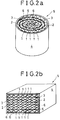
- Fig. 2a is a perspective view of a wound-shaped honeycomb structure of an embodiment of the present invention, while Fig. 2b a perspective view of the honeycomb structure in the form of a multilayered block.
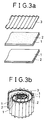
- Fig. 3a is a perspective view of the embodiment of the wound-shaped honeycomb structure in the preforming stage, while Fig. 3b a perspective view thereof in its being formed: Fig.
- FIG. 4a is a perspective view of another embodiment of the wound-shaped honeycomb structure in the preforming stage, while Fig. 4b a perspective view in its being formed.
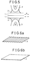
- Fig. 5 is an enlarged view showing the principal part of the outer side of the honeycomb structure according to the present invention.
- Fig. 6a is a perspective view of the corrugated plate, while Fig. 6b a perspective view of the flat plate.
- Fig. 7 is a sectional view of an embodiment showing the relative position of flat sheet and brazing filler metals.
- a strip of metallic corrugated plate 3 which is made by folding the flat metallic plate into continuously corrugated unevenness which is shown in the perspective view of Fig. 6a and a strip of metallic flat plate 1, are first prepared.
- Corrugated plate 3 is formed by corrugating or pressing a strip of metal foil of stainless steel or the like into a plurality of linear corrugated unevennesses, i.e., into crests and troughs folded parallelly and continuously with a fixed pitch and height.
- a strip of metallic foil such as stainless steel foil is used for the flat plate.
- corrugated plate 3 and flat plate 1 thus prepared are disposed alternately into multilayers, further another flat plate is inserted along the flat plate 1 so that they overlaps each other in the range of at least not less than two layers from the outside thereof.
- honeycomb structure 5 is formed overall into the prescribed configuration.
- each sheet of corrugated plate 3 and flat plate 1 of the same width are wound from the fixed center and overlapped into multilayers so as to be disposed alternately, and at the whole or a part of the contact line between corrugated plate 3 and flat plate 1, brazing filler metal 2 of the nickel or iron group is applied.
- flat plates 1 in the range of the first and second layers from the outside are disposed so that they overlap each other and brazing filler metal 2 is not provided between these two sheets of flat plate 1.
- corrugated plate 3 and flat plate 1 are welded therebetween, thereby forming wound-shaped honeycomb structure 5 which has a circular or ellipsoidal total section.
- one of said two flat sheets which is inserted into the multilayers of matrix without being welded to the other flat sheet can be made of electrically insulating material.
- electrically insulating material makes better electric current through the matrix when the matrix is heated electrically in order to obtain quicker reaction.
- honeycomb structure 5 in Fig. 2b a plurality of corrugated plates 3 and flat plates 1 which are all prepared in the form of plates with the same width and a fixed length are arranged vertically in multilayers so that they are disposed alternately, and brazing filler metal 2 is applied to the whole length or to a part of each abutting portion of corrugated plate 3 and flat plate 1. Further in the illustrated example, two sheets of flat plate 1 are overlapped in the first and second layers, from top to bottom and vice versa, but brazing filler metal 2 is not applied between these two sheets of flat plate 1.
- honeycomb structure 5 is made into the overall form of a multilayered matrix block.
- Fig. 3a is a perspective view of an example of a wound-shaped honeycomb structure 5 showing the preformed stage, while Fig. 3b a perspective view while it is being formed.
- honeycomb structure 5 in Fig. 3a all abutting portions of corrugated plate 3 and flat plate 1 are provided with strips of brazing filler metal 2 having substantially the same width as that of both plates and welded together therewith, where flat plate 1 is overlaps in all layers, different from the example in Fig. 2a.
- Fig. 4a is a perspective view of another example of a wound-shaped honeycomb structure 5 showing the pre formed stage, while 4b is a perspective view while it is being formed.
- corrugated plate 3 and flat plate 1 are provided at only a part of the abutting portion thereof with two spaced pieces of brazing filler metal 2 and welded together therewith, in which one of two overlapped sheets of flat plate 1 is in the form of a strip narrower than its partner, which is different from the examples shown in Figs. 2a and 3a.
- brazing filler metal 2 when brazing filler metal 2 is partially applied as described above, it is permissible to overlap the two sheets of flat plates 1 only for the range which can cover brazing filler metal 2.
- Fig. 1b is a view showing a catalytic converter which purifies exhaust gas C from an automobile engine, where 4 denotes a casing of cylindrical or square tubular form which acts as the outer casing for housing honeycomb structure 5, and both the casing and the honeycomb structure are welded by brazing filler metal 2.
- Fig. 7 is a sectional view of an embodiment showing the relative position of brazing filler metals 2 to a flat sheet 1, where brazing filler metals having the same wide width are used.
- the outer end of the brazing filler metal 2 at the upper left side is aligned with the left end of the flat sheet 1, while the outer end of the brazing filler metal 2 at the lower left side is deviately placed inward from the left end of the flat sheet 1.
- the outer end of the brazing metal 2 at the lower right side is aligned with the right end of the flat sheet, while the outer end of the brazing filler metal 2 at the upper right side is deviately placed inward from the right end of the flat sheet 1.
- the honeycomb structure 5 is manufactured.
- the strip of metallic corrugated plate 3 which is made by folding the metallic plate into continuously corrugated unevenness and the strip of flat metallic plate 1 are alternately disposed and welded into multilayers, whereby honeycomb structure 5 is made into the prescribed, overall configuration in the form of a wound or a multilayered block.
- two sheets of flat plate 1 are used in a pair so that they only overlap without being welded to each other.
- Fig. 5 is an enlarged view showing the principal part of the outer side of honeycomb structure 5 of this type.
- Corrugated plate 3 and flat plate 1 form a cell wall which comprises a plurality of cells 6 all substantially in the form of triangles, quadrangles, trapezoids, half hexagons or a plurality of hollow pillars of various types.
- honeycomb structure 5 has characteristics such as excellent strength-to-weight, light weight, high rigidity and strength, excellent formation for fluid flow, easy formability and economical production cost. Further, it has a large surface area per unit volume, that is, the surface area of the cell wall, i.e., corrugated plate 3 and flat plate 1, is large, so that it can be used in a catalytic converter for purifying exhaust gas from an automobile engine.
- corrugated plate 3 and flat plate 1 are provided with the catalyst on the surfaces thereof, and high temperature exhaust gas from the engine of the running automobile including noxious emissions can be purified by passing through a plurality of cells 6 thereby reacting with the attached catalyst.
- honeycomb structure 5 both the outer and inner sides of honeycomb structure 5 are heated due to the exhaust gas of uniform high temperature passing there-through and due to thermal reaction of the catalyst reacting with the gas. Since the outer side of honeycomb structure 5 is always cooled by open air through casing 4, its temperature rise when heated is relatively small and is rapidly cooled in the cooling process when the automobile engine is stopped, while the inner side of honeycomb structure 5 is spaced from open air so that it is not cooled by open air and its high temperature is maintained for a long time even in the cooling cycle after the automobile engine is stopped. Thus in honeycomb structure 5 which is used in an environment wherein heating and cooling cycles are repeated, a difference in the amount of thermal expansion and contraction occur.
- stress A is generated between the outer and inner sides thereof due to the large temperature difference.
- stress A acts in two parts of honeycomb structure 5 in mutually reverse directions which demarcate the range by the first or second layer from the outside thereof.
Priority Applications (4)
| Application Number | Priority Date | Filing Date | Title |
|---|---|---|---|
| DE69215679T DE69215679T2 (de) | 1992-09-26 | 1992-09-26 | Wabenkörper zum Reinigen von Abgas, und Verfahren zu seiner Herstellung |
| AT92116499T ATE145964T1 (de) | 1992-09-26 | 1992-09-26 | Wabenkörper zum reinigen von abgas, und verfahren zu seiner herstellung |
| EP92116499A EP0590171B1 (de) | 1992-09-26 | 1992-09-26 | Wabenkörper zum Reinigen von Abgas, und Verfahren zu seiner Herstellung |
| ES92116499T ES2097250T3 (es) | 1992-09-26 | 1992-09-26 | Estructura de panel para la purificacion de los gases de escape y su procedimiento de fabricacion. |
Applications Claiming Priority (1)
| Application Number | Priority Date | Filing Date | Title |
|---|---|---|---|
| EP92116499A EP0590171B1 (de) | 1992-09-26 | 1992-09-26 | Wabenkörper zum Reinigen von Abgas, und Verfahren zu seiner Herstellung |
Publications (2)
| Publication Number | Publication Date |
|---|---|
| EP0590171A1 true EP0590171A1 (de) | 1994-04-06 |
| EP0590171B1 EP0590171B1 (de) | 1996-12-04 |
Family
ID=8210060
Family Applications (1)
| Application Number | Title | Priority Date | Filing Date |
|---|---|---|---|
| EP92116499A Expired - Lifetime EP0590171B1 (de) | 1992-09-26 | 1992-09-26 | Wabenkörper zum Reinigen von Abgas, und Verfahren zu seiner Herstellung |
Country Status (4)
| Country | Link |
|---|---|
| EP (1) | EP0590171B1 (de) |
| AT (1) | ATE145964T1 (de) |
| DE (1) | DE69215679T2 (de) |
| ES (1) | ES2097250T3 (de) |
Cited By (7)
| Publication number | Priority date | Publication date | Assignee | Title |
|---|---|---|---|---|
| WO1996004509A1 (en) * | 1994-08-04 | 1996-02-15 | Heed Bjoern | Catalytic purification device |
| EP0690211A3 (de) * | 1994-05-30 | 1996-05-29 | Toyota Motor Co Ltd | Elektrisch beheizbarer Katalysator für eine Brennkraftmaschine |
| WO1997007889A1 (de) * | 1995-08-22 | 1997-03-06 | Emitec Gesellschaft Für Emissionstechnologie Mbh | Schichtartig aufgebaute bleche mit aufgewalztem lotmaterial und verfahren zum herstellen eines wabenkörpers daraus |
| US6207116B1 (en) | 1994-08-04 | 2001-03-27 | Enklaven Ab | Catalytic purification device |
| WO2009135767A1 (de) | 2008-05-07 | 2009-11-12 | Emitec Gesellschaft Für Emissionstechnologie Mbh | Wabenkörper mit radial verschieden ausgeführten verbindungsstellen |
| RU2493384C2 (ru) * | 2008-02-27 | 2013-09-20 | Эмитек Гезельшафт Фюр Эмиссионстехнологи Мбх | Сотовый элемент с зонами гибкости |
| CN113500320A (zh) * | 2021-07-29 | 2021-10-15 | 中车长春轨道客车股份有限公司 | 一种波纹板插接式箱型结构的底架前端模块组焊工艺 |
Citations (6)
| Publication number | Priority date | Publication date | Assignee | Title |
|---|---|---|---|---|
| EP0151229A1 (de) * | 1983-11-19 | 1985-08-14 | Süddeutsche Kühlerfabrik Julius Fr. Behr GmbH & Co. KG | Matrix für einen katalytischen Reaktor |
| DE8812924U1 (de) * | 1988-10-14 | 1988-12-01 | Sueddeutsche Kuehlerfabrik Julius Fr. Behr Gmbh & Co Kg, 7000 Stuttgart, De | |
| WO1989007488A1 (fr) * | 1988-02-11 | 1989-08-24 | Emitec Gesellschaft Für Emissionstechnologie Mbh | Corps en nid d'abeille, ayant notamment des toles en s partiellement renforcees |
| WO1990012951A1 (de) * | 1989-04-21 | 1990-11-01 | Emitec Gesellschaft Für Emissionstechnologie Mbh | Elektrisch leitfähiger wabenkörper mit mechanisch belastbaren elektrisch isolierenden zwischenschichten |
| US5084361A (en) * | 1990-04-17 | 1992-01-28 | Showa Aircraft Industry Co., Ltd. | Heat resistant structure |
| WO1992014913A1 (de) * | 1991-02-21 | 1992-09-03 | Emitec Gesellschaft Für Emissionstechnologie Mbh | Wabenkörper mit schraubensinn |
-
1992
- 1992-09-26 AT AT92116499T patent/ATE145964T1/de not_active IP Right Cessation
- 1992-09-26 ES ES92116499T patent/ES2097250T3/es not_active Expired - Lifetime
- 1992-09-26 EP EP92116499A patent/EP0590171B1/de not_active Expired - Lifetime
- 1992-09-26 DE DE69215679T patent/DE69215679T2/de not_active Expired - Fee Related
Patent Citations (6)
| Publication number | Priority date | Publication date | Assignee | Title |
|---|---|---|---|---|
| EP0151229A1 (de) * | 1983-11-19 | 1985-08-14 | Süddeutsche Kühlerfabrik Julius Fr. Behr GmbH & Co. KG | Matrix für einen katalytischen Reaktor |
| WO1989007488A1 (fr) * | 1988-02-11 | 1989-08-24 | Emitec Gesellschaft Für Emissionstechnologie Mbh | Corps en nid d'abeille, ayant notamment des toles en s partiellement renforcees |
| DE8812924U1 (de) * | 1988-10-14 | 1988-12-01 | Sueddeutsche Kuehlerfabrik Julius Fr. Behr Gmbh & Co Kg, 7000 Stuttgart, De | |
| WO1990012951A1 (de) * | 1989-04-21 | 1990-11-01 | Emitec Gesellschaft Für Emissionstechnologie Mbh | Elektrisch leitfähiger wabenkörper mit mechanisch belastbaren elektrisch isolierenden zwischenschichten |
| US5084361A (en) * | 1990-04-17 | 1992-01-28 | Showa Aircraft Industry Co., Ltd. | Heat resistant structure |
| WO1992014913A1 (de) * | 1991-02-21 | 1992-09-03 | Emitec Gesellschaft Für Emissionstechnologie Mbh | Wabenkörper mit schraubensinn |
Non-Patent Citations (1)
| Title |
|---|
| PATENT ABSTRACTS OF JAPAN vol. 15, no. 512 (C-898)26 December 1991 & JP-A-32 24 634 ( CATALER KOGYO ) 3 October 1991 * |
Cited By (13)
| Publication number | Priority date | Publication date | Assignee | Title |
|---|---|---|---|---|
| EP0690211A3 (de) * | 1994-05-30 | 1996-05-29 | Toyota Motor Co Ltd | Elektrisch beheizbarer Katalysator für eine Brennkraftmaschine |
| US5573731A (en) * | 1994-05-30 | 1996-11-12 | Toyota Jidosha Kabushiki Kaisha | Electrically heated catalytic converter for an engine |
| US6207116B1 (en) | 1994-08-04 | 2001-03-27 | Enklaven Ab | Catalytic purification device |
| WO1996004509A1 (en) * | 1994-08-04 | 1996-02-15 | Heed Bjoern | Catalytic purification device |
| WO1997007889A1 (de) * | 1995-08-22 | 1997-03-06 | Emitec Gesellschaft Für Emissionstechnologie Mbh | Schichtartig aufgebaute bleche mit aufgewalztem lotmaterial und verfahren zum herstellen eines wabenkörpers daraus |
| US6142362A (en) * | 1995-08-22 | 2000-11-07 | Emitec Gesellschaft Fuer Emissionstechnologie Mbh | Sheet metal layers of a layer-like configuration with rolled-on brazing material and process for the production of a honeycomb body therefrom |
| RU2493384C2 (ru) * | 2008-02-27 | 2013-09-20 | Эмитек Гезельшафт Фюр Эмиссионстехнологи Мбх | Сотовый элемент с зонами гибкости |
| WO2009135767A1 (de) | 2008-05-07 | 2009-11-12 | Emitec Gesellschaft Für Emissionstechnologie Mbh | Wabenkörper mit radial verschieden ausgeführten verbindungsstellen |
| CN102089507B (zh) * | 2008-05-07 | 2013-05-01 | 排放技术有限公司 | 具有径向不同实施的连接部位的蜂窝体 |
| RU2490485C2 (ru) * | 2008-05-07 | 2013-08-20 | Эмитек Гезельшафт Фюр Эмиссионстехнологи Мбх | Сотовый элемент с имеющими разное в радиальном направлении исполнение местами соединения |
| US8173268B2 (en) | 2008-05-07 | 2012-05-08 | Emitec Gesellschaft Fuer Emissionstechnologie Mbh | Honeycomb body having radially differently configured connecting points |
| CN113500320A (zh) * | 2021-07-29 | 2021-10-15 | 中车长春轨道客车股份有限公司 | 一种波纹板插接式箱型结构的底架前端模块组焊工艺 |
| CN113500320B (zh) * | 2021-07-29 | 2022-04-19 | 中车长春轨道客车股份有限公司 | 一种波纹板插接式箱型结构的底架前端模块组焊工艺 |
Also Published As
| Publication number | Publication date |
|---|---|
| DE69215679D1 (de) | 1997-01-16 |
| DE69215679T2 (de) | 1997-05-15 |
| ATE145964T1 (de) | 1996-12-15 |
| EP0590171B1 (de) | 1996-12-04 |
| ES2097250T3 (es) | 1997-04-01 |
Similar Documents
| Publication | Publication Date | Title |
|---|---|---|
| US5336472A (en) | Honeycomb structure for purifying exhaust gas and method of manufacturing same | |
| KR920009120B1 (ko) | 배기가스 정화용 촉매를 담지하기 위한 금속제 담지모체(擔持母體) | |
| US5084361A (en) | Heat resistant structure | |
| EP0590596B1 (de) | Metallischer Katalysatorträger zur Abgasreinigung | |
| KR870011350A (ko) | 금속판이 역방향으로 짜여진 벌집형 구조체, 특히 촉매지지체와 제조방법 | |
| JPH06182224A (ja) | 自己発熱型ハニカムフィルタ | |
| KR100495790B1 (ko) | 배기가스 촉매 장치용 단열부를 갖춘 하니컴 몸체 | |
| US5118477A (en) | Exhaust gas cleaning device | |
| EP0590171B1 (de) | Wabenkörper zum Reinigen von Abgas, und Verfahren zu seiner Herstellung | |
| JPH0744733Y2 (ja) | 排気ガス浄化装置 | |
| JPH05146685A (ja) | 排気ガス浄化用触媒及びその製造方法 | |
| EP1230978B1 (de) | Verfahren zur Herstellung einer Reaktorpackung aus gewelltem Blech | |
| JP3359061B2 (ja) | 排気ガス浄化用ハニカム担体 | |
| JP3308075B2 (ja) | 耐熱構造体の製造方法 | |
| JPH0663421A (ja) | 排気ガス浄化用触媒担体 | |
| EP1120163B1 (de) | Herstellungsverfahren für einen Metallträger-Katalysator | |
| JPH077534Y2 (ja) | 金属製ハニカム構造体 | |
| KR920005088B1 (ko) | 배기가스 정화용 촉매를 그위에 담지하기위한 금속제 담지모체(擔持母體) | |
| JPH0699081A (ja) | 排気ガス浄化装置 | |
| JP3065641B2 (ja) | 耐熱構造体およびその製造方法 | |
| JP3693706B2 (ja) | 排気ガス浄化用メタル担体 | |
| JP3262624B2 (ja) | メタル担体 | |
| JPH02280842A (ja) | 排ガス浄化触媒用メタル担体 | |
| JPH10235205A (ja) | 金属製触媒コンバータおよびその製造方法 | |
| JPH06106075A (ja) | 排気ガス浄化用ハニカム体 |
Legal Events
| Date | Code | Title | Description |
|---|---|---|---|
| PUAI | Public reference made under article 153(3) epc to a published international application that has entered the european phase |
Free format text: ORIGINAL CODE: 0009012 |
|
| AK | Designated contracting states |
Kind code of ref document: A1 Designated state(s): AT BE CH DE ES FR GB IT LI NL SE |
|
| 17P | Request for examination filed |
Effective date: 19940613 |
|
| 17Q | First examination report despatched |
Effective date: 19950329 |
|
| GRAH | Despatch of communication of intention to grant a patent |
Free format text: ORIGINAL CODE: EPIDOS IGRA |
|
| GRAH | Despatch of communication of intention to grant a patent |
Free format text: ORIGINAL CODE: EPIDOS IGRA |
|
| GRAA | (expected) grant |
Free format text: ORIGINAL CODE: 0009210 |
|
| AK | Designated contracting states |
Kind code of ref document: B1 Designated state(s): AT BE CH DE ES FR GB IT LI NL SE |
|
| PG25 | Lapsed in a contracting state [announced via postgrant information from national office to epo] |
Ref country code: NL Free format text: LAPSE BECAUSE OF FAILURE TO SUBMIT A TRANSLATION OF THE DESCRIPTION OR TO PAY THE FEE WITHIN THE PRESCRIBED TIME-LIMIT Effective date: 19961204 Ref country code: BE Effective date: 19961204 Ref country code: AT Effective date: 19961204 |
|
| REF | Corresponds to: |
Ref document number: 145964 Country of ref document: AT Date of ref document: 19961215 Kind code of ref document: T |
|
| ET | Fr: translation filed | ||
| REF | Corresponds to: |
Ref document number: 69215679 Country of ref document: DE Date of ref document: 19970116 |
|
| REG | Reference to a national code |
Ref country code: CH Ref legal event code: NV Representative=s name: R. A. EGLI & CO. PATENTANWAELTE |
|
| ITF | It: translation for a ep patent filed |
Owner name: STUDIO CONS. BREVETTUALE S.R.L. |
|
| PG25 | Lapsed in a contracting state [announced via postgrant information from national office to epo] |
Ref country code: SE Effective date: 19970304 |
|
| REG | Reference to a national code |
Ref country code: ES Ref legal event code: FG2A Ref document number: 2097250 Country of ref document: ES Kind code of ref document: T3 |
|
| NLV1 | Nl: lapsed or annulled due to failure to fulfill the requirements of art. 29p and 29m of the patents act | ||
| PLBE | No opposition filed within time limit |
Free format text: ORIGINAL CODE: 0009261 |
|
| STAA | Information on the status of an ep patent application or granted ep patent |
Free format text: STATUS: NO OPPOSITION FILED WITHIN TIME LIMIT |
|
| 26N | No opposition filed | ||
| REG | Reference to a national code |
Ref country code: GB Ref legal event code: IF02 |
|
| PGFP | Annual fee paid to national office [announced via postgrant information from national office to epo] |
Ref country code: GB Payment date: 20040921 Year of fee payment: 13 |
|
| PGFP | Annual fee paid to national office [announced via postgrant information from national office to epo] |
Ref country code: FR Payment date: 20040927 Year of fee payment: 13 |
|
| PGFP | Annual fee paid to national office [announced via postgrant information from national office to epo] |
Ref country code: ES Payment date: 20040930 Year of fee payment: 13 |
|
| PGFP | Annual fee paid to national office [announced via postgrant information from national office to epo] |
Ref country code: DE Payment date: 20041125 Year of fee payment: 13 |
|
| PGFP | Annual fee paid to national office [announced via postgrant information from national office to epo] |
Ref country code: CH Payment date: 20041222 Year of fee payment: 13 |
|
| PG25 | Lapsed in a contracting state [announced via postgrant information from national office to epo] |
Ref country code: GB Free format text: LAPSE BECAUSE OF NON-PAYMENT OF DUE FEES Effective date: 20050926 |
|
| PG25 | Lapsed in a contracting state [announced via postgrant information from national office to epo] |
Ref country code: ES Free format text: LAPSE BECAUSE OF NON-PAYMENT OF DUE FEES Effective date: 20050927 |
|
| PG25 | Lapsed in a contracting state [announced via postgrant information from national office to epo] |
Ref country code: LI Free format text: LAPSE BECAUSE OF NON-PAYMENT OF DUE FEES Effective date: 20050930 Ref country code: CH Free format text: LAPSE BECAUSE OF NON-PAYMENT OF DUE FEES Effective date: 20050930 |
|
| PG25 | Lapsed in a contracting state [announced via postgrant information from national office to epo] |
Ref country code: DE Free format text: LAPSE BECAUSE OF NON-PAYMENT OF DUE FEES Effective date: 20060401 |
|
| REG | Reference to a national code |
Ref country code: CH Ref legal event code: PL |
|
| GBPC | Gb: european patent ceased through non-payment of renewal fee |
Effective date: 20050926 |
|
| PG25 | Lapsed in a contracting state [announced via postgrant information from national office to epo] |
Ref country code: FR Free format text: LAPSE BECAUSE OF NON-PAYMENT OF DUE FEES Effective date: 20060531 |
|
| REG | Reference to a national code |
Ref country code: FR Ref legal event code: ST Effective date: 20060531 |
|
| PGFP | Annual fee paid to national office [announced via postgrant information from national office to epo] |
Ref country code: IT Payment date: 20060930 Year of fee payment: 15 |
|
| REG | Reference to a national code |
Ref country code: ES Ref legal event code: FD2A Effective date: 20050927 |
|
| PG25 | Lapsed in a contracting state [announced via postgrant information from national office to epo] |
Ref country code: IT Free format text: LAPSE BECAUSE OF NON-PAYMENT OF DUE FEES Effective date: 20070926 |