EP0589272A1 - Gerät für Kohlenstoffbeschichtung von optischen Fasern - Google Patents
Gerät für Kohlenstoffbeschichtung von optischen Fasern Download PDFInfo
- Publication number
- EP0589272A1 EP0589272A1 EP93114242A EP93114242A EP0589272A1 EP 0589272 A1 EP0589272 A1 EP 0589272A1 EP 93114242 A EP93114242 A EP 93114242A EP 93114242 A EP93114242 A EP 93114242A EP 0589272 A1 EP0589272 A1 EP 0589272A1
- Authority
- EP
- European Patent Office
- Prior art keywords
- reactor
- reactor vessel
- fiber
- reaction
- exit port
- Prior art date
- Legal status (The legal status is an assumption and is not a legal conclusion. Google has not performed a legal analysis and makes no representation as to the accuracy of the status listed.)
- Granted
Links
Images

Classifications
-
- C—CHEMISTRY; METALLURGY
- C03—GLASS; MINERAL OR SLAG WOOL
- C03C—CHEMICAL COMPOSITION OF GLASSES, GLAZES OR VITREOUS ENAMELS; SURFACE TREATMENT OF GLASS; SURFACE TREATMENT OF FIBRES OR FILAMENTS MADE FROM GLASS, MINERALS OR SLAGS; JOINING GLASS TO GLASS OR OTHER MATERIALS
- C03C13/00—Fibre or filament compositions
- C03C13/04—Fibre optics, e.g. core and clad fibre compositions
-
- C—CHEMISTRY; METALLURGY
- C03—GLASS; MINERAL OR SLAG WOOL
- C03C—CHEMICAL COMPOSITION OF GLASSES, GLAZES OR VITREOUS ENAMELS; SURFACE TREATMENT OF GLASS; SURFACE TREATMENT OF FIBRES OR FILAMENTS MADE FROM GLASS, MINERALS OR SLAGS; JOINING GLASS TO GLASS OR OTHER MATERIALS
- C03C25/00—Surface treatment of fibres or filaments made from glass, minerals or slags
- C03C25/10—Coating
- C03C25/12—General methods of coating; Devices therefor
- C03C25/22—Deposition from the vapour phase
- C03C25/223—Deposition from the vapour phase by chemical vapour deposition or pyrolysis
-
- C—CHEMISTRY; METALLURGY
- C03—GLASS; MINERAL OR SLAG WOOL
- C03C—CHEMICAL COMPOSITION OF GLASSES, GLAZES OR VITREOUS ENAMELS; SURFACE TREATMENT OF GLASS; SURFACE TREATMENT OF FIBRES OR FILAMENTS MADE FROM GLASS, MINERALS OR SLAGS; JOINING GLASS TO GLASS OR OTHER MATERIALS
- C03C25/00—Surface treatment of fibres or filaments made from glass, minerals or slags
- C03C25/10—Coating
- C03C25/104—Coating to obtain optical fibres
- C03C25/106—Single coatings
- C03C25/1061—Inorganic coatings
- C03C25/1062—Carbon
Definitions
- This invention relates to an apparatus for providing a carbon-containing coating on optical waveguide fibers.
- Optical waveguide fibers are typically provided with abrasion-resistant coatings such as silicone or polyurethane acrylate, for example. These coatings are usually applied to the pristine surface of the fiber during the fiber drawing process. While these coatings provide protection from abrasion, they do not provide adequate protection from corrosion or hydrogen attack.
- abrasion-resistant coatings such as silicone or polyurethane acrylate, for example.
- Microcracks in a fiber surface are regions which are more susceptible to such attack, especially when the fiber is under stress.
- the growth of these microcracks due to chemical attack reduces the mechanical strength of a fiber and may result in static fatigue or sudden failure of the fiber.
- Carbon coatings are known to produce water resistant, high strength optical fibers. See, for example, Kao et al. U.S. Patent No. 4,183,621. Carbon coatings have also been shown to be sufficiently impermeable to hydrogen diffusion. Lemaire et al., "Hydrogen Permeation in Optical Fibres with Hermetic Carbon Coatings", Electronics Letters, vol. 24, no. 21, pages 1323-24, October 13, 1988; Lu et al., “Recent Developments in Hermetically Coated Optical Fiber", J. of Lightwave Technology, vol. 6, no. 2, pages 240-244, February, 1988; Lu et al., "Hermetically Coated Optical Fibers", International Wire & Cable symposium Proceedings, pages 241-244, 1987.
- One method for providing an optical waveguide fiber involves exposing a fiber to a carbon-containing reactant gas and decomposing the reactant gas by heating it.
- the required heat for the reaction may be provided by the temperature of the fiber itself, external heating means, or by some combination of the two.
- the decomposition of the reactant gas produces a high molecular weight reaction product, which forms the desired carbon layer on the fiber, and reaction by-products.
- the reaction by-products can be either high molecular weight dry particulate matter similar to carbon black, or low molecular weight oily droplets which solidify to a gummy or glassy material. Also, some portion of the reactant gas may remain unreacted.
- Low molecular weight reaction by-products are preferentially formed at lower temperatures.
- High molecular weight reaction by-products are rapidly formed at temperatures above about 150 °C. These high molecular weight reaction by-products can be formed as reactant gas flows along with the fiber through the reactor and is exposed to temperatures in the vicinity of the fiber which are higher than 150 °C.
- Prior art processes and devices for manufacturing optical fibers with carbon coatings have encountered various problems. Alignment of the reactor, in which the carbon coating is applied to a fiber, with the other components of the fiber drawing apparatus is necessary for process stability and repeatability.
- Prior art devices which have disclosed the material used in construction of the reactor have disclosed the use of quartz or silica tubes. See, for example, Oohashi et al. U.S. Patent No. 5,037,464; Ishiguro et al. European Patent Publication No. 0,374,926; Schultz et al. U.S. Patent No. 4,735,856; Evans et al. UK Patent Application No. 2,156,858. Due to the complex shapes required in the reactor design, fabrication of the reactor using quartz or silica lacks dimensional repeatability which adversely affects the ability to initially align the reactor on the fiber drawing apparatus and to maintain alignment during the fiber drawing process.
- quartz or silica reactors provide insulating properties, elevating the temperature within the reactor and accelerating the formation of undesired reaction by-products.
- the rate of formation of high molecular weight reaction by-products is greater than the formation of low molecular weight reaction by-products.
- High molecular weight reaction by-products may build up within the reactor and impinge on the fiber, damaging the carbon coating and possibly the fiber itself. Because these reaction by-products build up over time, the ability to produce long lengths of coated optical fiber is reduced. In some cases, entire production lots of greater than 100 km of fiber are rejected to ensure the quality of the coating if build up of high molecular weight reaction by-products is detected within the reactor.
- Bennett et al. U.S. Patent No. 5,152,817, to be issued on October 6, 1992, is assigned to the Assignee of the present application. Bennett et al. discloses an apparatus for providing long lengths of optical waveguide fiber with a carbon-containing coating without the build up of high molecular weight reaction by-products within the reactor.
- the apparatus of Bennett et al. is shown in FIG. 1. It consists of a combination of an upper isolation chamber 1, reaction chamber 2, receiving chamber 3, and lower isolation chamber 4. Fiber 5 enters the apparatus at fiber inlet 6 and exits through external fiber exit 7. Reactant gas is introduced at inlet 8. Reaction by-products are exhausted through external fiber exit port 7 or through outlet pipe 9 which can be optionally provided. Shield gas is introduced to upper isolation chamber 1 and lower isolation chamber 4 through shield gas inlets 10 and 11, respectively. The inside diameter of external fiber exit port 7 is the same as the internal diameter of internal fiber exit port 13. In a preferred embodiment, the portion of reaction tube 14 within chamber 2 may be perforated, as shown, to evenly distribute the reactant gas radially around fiber 5.
- reaction tube 14 of Bennett et al. are selected to ensure adequate coating thickness and to reduce the build up of high molecular weight reaction by-products inside the reactor.
- the preferred length is about 5-6.5 cm for an inside diameter (ID) of 1 cm.
- ID inside diameter
- oily reaction by-product may build up on the interior surfaces of reaction tube 14.
- Reaction by-products will deposit on the interior walls of receiving chamber 3.
- the inside diameter of receiving chamber 3 must be at least about 1 inch (2.5 cm) and the length at least 4 inches (10 cm) for the build up of reaction by-products on the walls of receiving chamber 3 to present no problem in the fiber drawing or coating processes.
- Bennett et al. discloses a reactor where the bottom surface of the receiving chamber is angled downwardly away from opening 12 through which the fiber exits the receiving chamber. This angle is disclosed in a specific example as being 50° with respect to the fiber axis.
- this angled surface is to prevent any oily reaction by-products which may deposit on the bottom surface of the receiving chamber from flowing toward opening 12 before that deposit solidifies.
- the reactor in Bennett et al. is made of glass (typically, "PYREX®") except for upper isolation chamber 1 and reaction chamber 2, which are made of aluminum. After a preform is drawn into fiber, the reactor is removed from the drawing apparatus and the glass portion is heated to about 900 °F (480 °C) for a period of about four hours in an oxygen-containing atmosphere to burn off any reaction by-products which may have deposited on the surfaces of the reactor.
- PYREX® glass
- upper isolation chamber 1 and reaction chamber 2 which are made of aluminum.
- Glass reactors have been used instead of metal reactors for several reasons.
- the burn off method is used with a metal reactor, it would require lower temperatures for unacceptably longer periods of time than are used for burning off deposits on glass reactors.
- an aluminum reactor exposed to an oxygen atmosphere at 750 °F (400 °C) for a period of ten hours still exhibited some residue from the build up of reaction by-products.
- Jochem European Patent Publication No. 0,393,755 discloses a method of manufacturing an optical fiber with a coating wherein the temperature of the reactor walls is below 800 °C.
- the restriction on the maximum temperature of the reactor walls is designed to reduce the build up of reaction by-products on the reactor walls.
- the reactor may comprise an insulated wall or a heating device ... in order to preclude that the glass fibre cools too rapidly.” col. 4, lines 20-23.
- Jochem only discloses reactor wall temperatures ranging from 600 to 900 °C in a specific example. col. 7, lines 10-29. However, even at 600 °C, we believe significant amounts of reaction by-products will be deposited on the reactor walls.
- This object is achieved by using a reactor made of aluminum. This allows the reaction at or near the reactor walls to occur at temperatures which reduce the formation of high molecular weight reaction by-products, and it provides a cooler reactor wall which retards the conversion of low molecular weight reaction by-products which are deposited on the reactor walls to high molecular weight reaction by-products.
- the design of the fiber exit of the reactor utilizes a dual fiber exit port with different port IDs which further reduces the build up of high molecular weight reaction by-products and subsequent damage to the carbon coating or the fiber itself.
- an inert gas shield is used to reduce build up of high molecular weight reaction by-products at the fiber exit and to prevent oxygen from entering the reactor.
- FIG. 1 is a schematic of a prior art apparatus for providing carbon coatings on optical fibers.
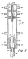
- FIG. 2 is a cross-sectional representation of an apparatus in accordance with the present invention.
- FIG. 3 is a cross-sectional representation of a section of an apparatus including perforations in accordance with the present invention.
- Equipment for the drawing of optical fiber from an optical fiber preform is well known in the art.
- a furnace is used to heat a preform to a temperature at which a fiber can be drawn therefrom.
- the diameter of the drawn fiber is measured by a non-contact device.
- the fiber is then typically coated with an abrasion-resistant coating and wound onto spools. See, for example, Jaeger et al., "Fiber Drawing and Control", Optical Fiber Telecommunications, chap. 9, pages 263-298, Academic Press, 1979. If application of a carbon coating is desired, this is performed after the fiber is drawn from the preform and before the abrasion-resistant coating is applied.
- FIG. 2 shows one embodiment of the present invention. Only the carbon coating reactor is shown.
- the reactor 20 includes upper isolation chamber 21, reaction chamber 22, receiving chamber 23, and lower isolation chamber 24.
- Reactant gas inlets 25 and 38 provide for the introduction of reactant gas to reaction chamber 22.
- Reactor 20 is preferably constructed of aluminum.
- the use of aluminum for the reactor allows for tight tolerances ( ⁇ 0.005") in the manufacture of the reactor. These tighter manufacturing tolerances provide for more repeatable alignment of the reactor with the other devices of the fiber drawing apparatus. Also, with a metal reactor, any reactions of reactant gases at or near the reactor walls will occur at a cooler temperature than with the use of insulating materials such as quartz or silica. Because of the high thermal conductivity of aluminum, no external cooling is required to provide the benefit of reduced reactor temperature.
- Reactor 20 is positioned on the fiber drawing apparatus such that the temperature of the fiber is sufficient to produce the desired reaction of the reactant gases.
- Fiber 26 enters reactor 20 at fiber inlet 33.
- the direction of fiber movement is shown by the arrow.
- the temperature of fiber 26 at fiber inlet 33 is difficult to measure due to the small size of the fiber and drawing conditions, especially the draw speed. However, we estimate the temperature to be in the range of about 1,200-1,800 °C, with a minimum fiber temperature of about 1,000 °C being necessary within the reactor for the reaction to occur.
- Upper isolation chamber 21 prevents the entry of ambient atmosphere into the top of the reactor.
- Upper isolation gas is introduced into upper isolation chamber 21 through upper isolation gas inlets 34 and 39.
- tube 40 may be perforated, as shown in FIG.
- the perforations are in a spiralled pattern, i.e., the perforations in a given row are not vertically aligned with the perforations in either the row immediately above or the row immediately below that given row.
- Reactant gases are introduced through reactant gas inlets 25 and 38.
- perforations are provided in the portion of reaction tube 27 within chamber 22, as shown in FIG. 3, to evenly distribute the reactant gas radially about fiber 26.
- the perforations are in a spiralled pattern, i.e., the perforations in a given row are not vertically aligned with the perforations in either the row immediately above or the row immediately below that given row.
- the reactant gases react immediately upon contacting fiber 26, producing the desired carbon coating. The reaction continues as the fiber moves through reaction chamber 27. A boundary layer of high molecular weight reaction by-products, low molecular weight reaction by-products and unreacted gases forms near or above the surface of the moving fiber.
- the reaction by-products and unreacted gases will accelerate to the fiber drawing speed and move with fiber 26 as it passes through reactor 20.
- the diameter of internal fiber exit port 28 is chosen to avoid disruption of the boundary layer formed near or above the fiber surface. This prevents high molecular weight reaction by-products contained in the boundary layer from building up around internal fiber exit port 28.
- the internal diameter of internal fiber exit port 28 is 0.51 inches (13 mm).
- shield gas may be any inert gas which keeps the reactor free of oxygen, with nitrogen being preferred.
- lower isolation tube 32 having a larger diameter than internal fiber exit port 28, is provided, and lower isolation tube 32 is perforated to radially distribute the shield gas flow about fiber 26.
- the shield gas directs the boundary layer formed near or above the fiber surface out of the reactor through external fiber exit port 29, sweeping any high molecular weight reaction by-products out of the reactor through external fiber exit port 29.
- the shield gas also prevents the entry of ambient atmosphere into the reactor through external fiber exit port 29.
- the internal diameter of external fiber exit port 29 is 0.255 inches (6 mm).
- Reaction by-products contained in the boundary layer are exhausted through external fiber exit port 29. These reaction by-products deposit on glass tube 41, which is provided for that purpose. Glass tube 41 is coated with a black glassy residue after a preform is drawn. This residue does not interfere with the fiber drawing or coating processes.
- receiving chamber exhaust ports 36 and 37 are provided to exhaust additional reaction by-products.
- the reactor body may be made of any material which exhibits sufficient thermal conductivity to cool the reactor body.
- Means for auxiliary cooling of the reactor may optionally be provided if the material used in construction of the reactor does not exhibit sufficient thermal conductivity to cool the reactor body without auxiliary cooling.
- the auxiliary cooling may be passive (for example, fins attached to the exterior surfaces of the reactor body to increase the available surface area for convection cooling) or active (for example, a cooling jacket assembly attached to the exterior of the reactor body with cooling fluid circulation).
- aluminum is preferred as it requires no auxiliary cooling and is easy to machine to tight tolerances.
- the temperature of the reactor walls is less than about 150 °C when aluminum is used without any auxiliary cooling.
- any reaction by-products which form at or near the walls of the reactor will have a low molecular weight and an oilier, more flowing consistency which will tend to cause these low molecular weight reaction by-products to deposit on the reactor walls.
- substantially all of the high molecular weight reaction by-products which form within the reactor are entrained within the boundary layer near or above the fiber surface and are not deposited on the walls of the reactor as described above.
- Some high molecular weight reaction by-products may escape the boundary layer, particularly at points where the boundary layer is disrupted. Some disruption of the boundary layer occurs where reaction tube 27 opens into receiving chamber 23. Any high molecular weight reaction by-products which escape the boundary layer at this point will stick to the film formed on the receiving chamber walls by the low molecular weight reaction by-products. Additional low molecular weight reaction by-products will then tend to deposit over the high molecular weight reaction by-products. Because the receiving chamber is relatively large in diameter, as compared to the reaction tube and the internal and external fiber exit ports, any such build up does not interfere with the fiber drawing or coating process.
- Shield gas may be provided at internal fiber exit port 28 by shield gas inlets not shown. Inert gases other than nitrogen may be used as the shield gas provided such other gases keep the reactor free of oxygen. Nitrogen is preferred because of its availability, ease in handling, and relatively low cost.
- the reactor is an assembly of smaller units. Upper isolation chamber 21 is bolted to reaction chamber 22. Reaction chamber 22 is attached to receiving chamber 23 via a rotating connection. Lower isolation chamber 24 is attached to receiving chamber 23 using a similar connection. These connections allow for quick disassembly of the reactor to facilitate cleaning, and quick reassembly of the reactor for reinstallation on the fiber drawing apparatus.
- Test fibers were made using the present invention.
- the fibers were drawn from optical waveguide preforms which were produced using standard outside vapor deposition (OVD) techniques as described in, for example, Berkey U.S. Patent No. 4,453,961 and Berkey U.S. Patent No. 4,486,212.
- OLED outside vapor deposition
- any method suitable for producing preforms from which optical fibers are drawn may be utilized.
- vapor axial deposition (VAD) techniques as described in Inada, "Recent Progress in Fiber Fabrication Techniques by Vapor-Phase Axial Deposition", IEEE J. of Quantum Electronics, vol. QE-18, no. 10, October, 1982, and Suto et al. U.S. Patent No.
- 4,367,085 may also be used to produce optical fiber preforms.
- Fiber was drawn from the preforms on standard optical fiber drawing equipment.
- the draw speed was 9 m/sec.
- the top of the reactor was located about 5.18 inches (13.2 cm) from the bottom of the draw furnace.
- Draw speeds in the range of about 7-9 m/sec have been tested, and we believe that speeds up to about 15 m/sec are achievable using the present invention.
- the position of the reactor will vary based on the type of fiber being coated, draw speed and other fiber drawing process parameters.
- the reactant gas used was methyl acetylene at a flow rate of about 0.2 liters per minute.
- Shield gas was provided only at upper isolation chamber 21 and lower isolation chamber 24 at a flow rate of about 2 liters per minute for each chamber.
- Nitrogen was introduced through upper isolation gas inlets 34 and 39 and shield gas inlets 30 and 31.
- the reactor was visually inspected after each preform was drawn. No significant build up of high molecular weight reaction by-products at or near internal fiber exit port 28 or external fiber exit port 29 was detected in any of the tests. Build up of oily, low molecular weight reaction by-products was detected. This build up solidified and did not interfere with the coating process.
- any reaction by-products which were deposited on the walls of the reactor were removed after the fiber drawing process was complete. This removal was accomplished by directing a stream of powdered plastic (allypolycarbonate) at about 80 psi at the surfaces of the reactor. This process takes about 5 minutes. With prior reactors made of glass, the heating process used to remove reaction by-products deposited on reactor surfaces takes about four hours at 900 °F (480 °C).
- the aluminum reactor of the present invention cannot be subjected to such high temperatures without possible deformation of the reactor itself. In one test, an aluminum reactor was heated to about 750 °F (400 °C) for about ten hours in an oxygen atmosphere. There was still some of the residue from the build up of reaction by-products on the reactor walls.
- the "blasting" technique described above is preferable as it is a vast improvement in turn around time and effectiveness of cleaning over the heating process.
- the fibers made under the above conditions were tested for hydrogen permeation, strength, and fatigue.
- the hydrogen permeation test is involves exposing fibers to pure hydrogen at 11 atmospheres pressure and 85 °C for 21 days. 29 fibers from 10 different preforms were tested. The average attenuation increase at 1240 nm was 0.006 dB/km for fibers made using the present invention. 1240 nm represents the first harmonic of the fundamental hydrogen vibration and is used to characterize the level of hydrogen permeability of an optical fiber.
- Fibers from the same 10 preforms were tested for strength and fatigue performance.
- the average mean strength was 477 kpsi with a 1 ⁇ of 32.7 kpsi. Strength was tested using 0.5 m gage lengths.
- the average Weibull slope was 73 with a 1 ⁇ of 11.
Priority Applications (1)
| Application Number | Priority Date | Filing Date | Title |
|---|---|---|---|
| EP97200300A EP0776869B1 (de) | 1992-09-23 | 1993-09-06 | Verfahren zum Anbringen eines Kohlenstoff auf optischen Fasern |
Applications Claiming Priority (2)
| Application Number | Priority Date | Filing Date | Title |
|---|---|---|---|
| US950072 | 1992-09-23 | ||
| US07/950,072 US5346520A (en) | 1992-09-23 | 1992-09-23 | Apparatus for applying a carbon coating to optical fibers |
Related Child Applications (2)
| Application Number | Title | Priority Date | Filing Date |
|---|---|---|---|
| EP97200300A Division EP0776869B1 (de) | 1992-09-23 | 1993-09-06 | Verfahren zum Anbringen eines Kohlenstoff auf optischen Fasern |
| EP97200300.8 Division-Into | 1997-02-04 |
Publications (2)
| Publication Number | Publication Date |
|---|---|
| EP0589272A1 true EP0589272A1 (de) | 1994-03-30 |
| EP0589272B1 EP0589272B1 (de) | 1997-11-12 |
Family
ID=25489901
Family Applications (2)
| Application Number | Title | Priority Date | Filing Date |
|---|---|---|---|
| EP97200300A Expired - Lifetime EP0776869B1 (de) | 1992-09-23 | 1993-09-06 | Verfahren zum Anbringen eines Kohlenstoff auf optischen Fasern |
| EP93114242A Expired - Lifetime EP0589272B1 (de) | 1992-09-23 | 1993-09-06 | Gerät für Kohlenstoffbeschichtung von optischen Fasern |
Family Applications Before (1)
| Application Number | Title | Priority Date | Filing Date |
|---|---|---|---|
| EP97200300A Expired - Lifetime EP0776869B1 (de) | 1992-09-23 | 1993-09-06 | Verfahren zum Anbringen eines Kohlenstoff auf optischen Fasern |
Country Status (8)
| Country | Link |
|---|---|
| US (3) | US5346520A (de) |
| EP (2) | EP0776869B1 (de) |
| JP (1) | JPH06191901A (de) |
| KR (1) | KR100255968B1 (de) |
| AU (1) | AU4741493A (de) |
| CA (1) | CA2105711A1 (de) |
| DE (2) | DE69315157T2 (de) |
| TW (1) | TW274123B (de) |
Cited By (1)
| Publication number | Priority date | Publication date | Assignee | Title |
|---|---|---|---|---|
| DE19801700A1 (de) * | 1998-01-17 | 1999-07-22 | Cit Alcatel | Vorrichtung zum Beschichten einer Faser |
Families Citing this family (17)
| Publication number | Priority date | Publication date | Assignee | Title |
|---|---|---|---|---|
| US5346520A (en) * | 1992-09-23 | 1994-09-13 | Corning Incorporated | Apparatus for applying a carbon coating to optical fibers |
| KR19980054093A (ko) * | 1996-12-27 | 1998-09-25 | 박병재 | 전자제어파워스티어링 |
| FR2761979B1 (fr) * | 1997-04-14 | 1999-05-28 | Alsthom Cge Alcatel | Procede et appareil de fabrication d'une fibre optique munie d'un revetement hermetique |
| EP0998431A1 (de) * | 1997-07-15 | 2000-05-10 | Corning Incorporated | Verminderte h2 empfindlichkeit in optischen fasern |
| DE29718521U1 (de) * | 1997-10-18 | 1998-01-02 | Alsthom Cge Alcatel | Vorrichtung zum Aufbringen eines Beschichtungsmaterials auf eine Faser |
| US6063200A (en) * | 1998-02-10 | 2000-05-16 | Sarcos L.C. | Three-dimensional micro fabrication device for filamentary substrates |
| US6325981B1 (en) | 1999-09-28 | 2001-12-04 | Alcatel | Apparatus and method for curing a photocurable coating provided on a fiber |
| US6630029B2 (en) * | 2000-12-04 | 2003-10-07 | General Electric Company | Fiber coating method and reactor |
| TW560102B (en) * | 2001-09-12 | 2003-11-01 | Itn Energy Systems Inc | Thin-film electrochemical devices on fibrous or ribbon-like substrates and methd for their manufacture and design |
| US20030068559A1 (en) * | 2001-09-12 | 2003-04-10 | Armstrong Joseph H. | Apparatus and method for the design and manufacture of multifunctional composite materials with power integration |
| US20030059526A1 (en) * | 2001-09-12 | 2003-03-27 | Benson Martin H. | Apparatus and method for the design and manufacture of patterned multilayer thin films and devices on fibrous or ribbon-like substrates |
| US6789400B2 (en) * | 2001-11-30 | 2004-09-14 | The Boc Group, Inc. | Cap assembly and optical fiber cooling process |
| US20080156635A1 (en) * | 2006-12-31 | 2008-07-03 | Simon Bogdan M | System for processes including fluorination |
| US7829195B2 (en) * | 2006-12-31 | 2010-11-09 | Intel Corporation | Fluorination pre-treatment of heat spreader attachment indium thermal interface material |
| EP2138471A1 (de) * | 2008-06-25 | 2009-12-30 | Acreo AB | Ablagerung einer atomaren Schicht aus Wasserstoffdämmbeschichtungen auf Glasfasern |
| JP5587323B2 (ja) | 2008-09-26 | 2014-09-10 | コーニング インコーポレイテッド | 高開口数多モード光ファイバ |
| US20180230049A1 (en) * | 2017-02-13 | 2018-08-16 | Baker Hughes Incorporated | Downhole optical fiber with array of fiber bragg gratings and carbon-coating |
Citations (4)
| Publication number | Priority date | Publication date | Assignee | Title |
|---|---|---|---|---|
| EP0374926A1 (de) * | 1988-12-21 | 1990-06-27 | Sumitomo Electric Industries, Ltd. | Verfahren zur Herstellung einer Kohlenstoff-beschichteten optischen Faser |
| EP0393755A2 (de) * | 1989-04-19 | 1990-10-24 | Koninklijke Philips Electronics N.V. | Verfahren zum Herstellen einer optischen Faser mit einer hermetisch abschliessenden Bedeckung |
| EP0424012A1 (de) * | 1989-10-19 | 1991-04-24 | AT&T Corp. | Verfahren zur und Vorrichtung für die Beschichtung von optischen Fasern |
| EP0498939A1 (de) * | 1991-01-15 | 1992-08-19 | Corning Incorporated | Reaktor für die Beschichtung von optischen Fasern |
Family Cites Families (26)
| Publication number | Priority date | Publication date | Assignee | Title |
|---|---|---|---|---|
| GB1513245A (en) * | 1974-06-18 | 1978-06-07 | Girling Ltd | Actuator assembly for vehicle brakes |
| US4081313A (en) * | 1975-01-24 | 1978-03-28 | Applied Materials, Inc. | Process for preparing semiconductor wafers with substantially no crystallographic slip |
| US4118211A (en) * | 1977-06-22 | 1978-10-03 | The United States Of America As Represented By The Secretary Of The Army | Method of maintaining the strength of optical fibers |
| US4183621A (en) * | 1977-12-29 | 1980-01-15 | International Telephone And Telegraph Corporation | Water resistant high strength fibers |
| NL7902201A (nl) * | 1979-03-21 | 1980-09-23 | Philips Nv | Werkwijze en inrichting voor het vervaardigen van op- tische fibers alsmede optische fibers vervaardigd met de werkwijze. |
| US4367085A (en) * | 1980-01-07 | 1983-01-04 | Nippon Telegraph & Telephone Public Corporation | Method of fabricating multi-mode optical fiber preforms |
| US4356673A (en) * | 1980-08-11 | 1982-11-02 | Alcan Aluminum Corporation | Siding panel systems and methods of installation |
| US4512629A (en) * | 1982-03-30 | 1985-04-23 | Hewlett-Packard Company | Optical fiber with hermetic seal and method for making same |
| US4453961A (en) * | 1982-07-26 | 1984-06-12 | Corning Glass Works | Method of making glass optical fiber |
| US4486212A (en) * | 1982-09-29 | 1984-12-04 | Corning Glass Works | Devitrification resistant flame hydrolysis process |
| GB8401089D0 (en) * | 1984-01-16 | 1984-02-15 | Gen Electric Co Plc | Coating optical fibres |
| US4592932A (en) * | 1984-06-26 | 1986-06-03 | Itt Corporation | Hermetic coating for an optical fiber |
| IT1184909B (it) * | 1985-03-18 | 1987-10-28 | Cselt Centro Studi Lab Telecom | Procedimento ed apparecchiatura per la riduzione dei difetti di volume e di superficie nelle fibre ottiche in silice |
| US4735856A (en) * | 1986-03-31 | 1988-04-05 | Spectran Corporation | Hermetic coatings for optical fiber and product |
| US4832706A (en) * | 1986-09-24 | 1989-05-23 | International Limited | Abrasive media |
| US5000541A (en) * | 1987-09-18 | 1991-03-19 | At&T Bell Laboratories | Hermetically sealed optical fibers |
| CA2004234C (en) * | 1988-12-01 | 1994-04-19 | Keiji Oohashi | Optical fiber production method |
| AU629648B2 (en) * | 1989-06-13 | 1992-10-08 | Nippon Telegraph & Telephone Corporation | Hermetically coated optical fiber and production of the same |
| US5256205A (en) * | 1990-05-09 | 1993-10-26 | Jet Process Corporation | Microwave plasma assisted supersonic gas jet deposition of thin film materials |
| US5043001A (en) * | 1990-05-29 | 1991-08-27 | Corning Incorporated | Method and apparatus for fiber cooling |
| US5256177A (en) * | 1991-01-15 | 1993-10-26 | Corning Incorporated | Method for coating optical fibers |
| NO920574L (no) * | 1991-02-14 | 1992-08-17 | Sumitomo Electric Industries | Fremgangsmaate og apparat for fremstilling av belagte optiske fibre |
| US5354348A (en) * | 1991-05-12 | 1994-10-11 | Mitsubishi Cable Industries, Ltd. | Method for producing silica glass optical fiber with carbon coating |
| JPH05124841A (ja) * | 1991-06-12 | 1993-05-21 | Sumitomo Electric Ind Ltd | ハーメチツクコート光フアイバの製造方法 |
| US5346520A (en) * | 1992-09-23 | 1994-09-13 | Corning Incorporated | Apparatus for applying a carbon coating to optical fibers |
| US5377491A (en) * | 1992-12-11 | 1995-01-03 | Praxair Technology, Inc. | Coolant recovery process |
-
1992
- 1992-09-23 US US07/950,072 patent/US5346520A/en not_active Expired - Fee Related
-
1993
- 1993-09-06 EP EP97200300A patent/EP0776869B1/de not_active Expired - Lifetime
- 1993-09-06 EP EP93114242A patent/EP0589272B1/de not_active Expired - Lifetime
- 1993-09-06 DE DE69315157T patent/DE69315157T2/de not_active Expired - Fee Related
- 1993-09-06 DE DE69327010T patent/DE69327010T2/de not_active Expired - Fee Related
- 1993-09-08 CA CA002105711A patent/CA2105711A1/en not_active Abandoned
- 1993-09-17 AU AU47414/93A patent/AU4741493A/en not_active Abandoned
- 1993-09-22 KR KR1019930019352A patent/KR100255968B1/ko not_active IP Right Cessation
- 1993-09-22 JP JP5257530A patent/JPH06191901A/ja active Pending
- 1993-11-08 TW TW082109455A patent/TW274123B/zh active
-
1995
- 1995-06-07 US US08/473,695 patent/US5611835A/en not_active Expired - Fee Related
-
1996
- 1996-11-27 US US08/757,989 patent/US5792234A/en not_active Expired - Lifetime
Patent Citations (5)
| Publication number | Priority date | Publication date | Assignee | Title |
|---|---|---|---|---|
| EP0374926A1 (de) * | 1988-12-21 | 1990-06-27 | Sumitomo Electric Industries, Ltd. | Verfahren zur Herstellung einer Kohlenstoff-beschichteten optischen Faser |
| EP0393755A2 (de) * | 1989-04-19 | 1990-10-24 | Koninklijke Philips Electronics N.V. | Verfahren zum Herstellen einer optischen Faser mit einer hermetisch abschliessenden Bedeckung |
| EP0424012A1 (de) * | 1989-10-19 | 1991-04-24 | AT&T Corp. | Verfahren zur und Vorrichtung für die Beschichtung von optischen Fasern |
| EP0498939A1 (de) * | 1991-01-15 | 1992-08-19 | Corning Incorporated | Reaktor für die Beschichtung von optischen Fasern |
| US5152817A (en) * | 1991-01-15 | 1992-10-06 | Corning Incorporated | Reactor for coating optical fibers |
Cited By (1)
| Publication number | Priority date | Publication date | Assignee | Title |
|---|---|---|---|---|
| DE19801700A1 (de) * | 1998-01-17 | 1999-07-22 | Cit Alcatel | Vorrichtung zum Beschichten einer Faser |
Also Published As
| Publication number | Publication date |
|---|---|
| EP0776869A2 (de) | 1997-06-04 |
| US5792234A (en) | 1998-08-11 |
| DE69315157D1 (de) | 1997-12-18 |
| US5611835A (en) | 1997-03-18 |
| EP0776869A3 (de) | 1997-07-30 |
| JPH06191901A (ja) | 1994-07-12 |
| DE69315157T2 (de) | 1998-03-12 |
| EP0589272B1 (de) | 1997-11-12 |
| TW274123B (de) | 1996-04-11 |
| EP0776869B1 (de) | 1999-11-10 |
| AU4741493A (en) | 1994-03-31 |
| US5346520A (en) | 1994-09-13 |
| KR100255968B1 (ko) | 2000-05-01 |
| CA2105711A1 (en) | 1994-03-24 |
| KR940006949A (ko) | 1994-04-26 |
| DE69327010D1 (de) | 1999-12-16 |
| DE69327010T2 (de) | 2000-04-20 |
Similar Documents
| Publication | Publication Date | Title |
|---|---|---|
| US5346520A (en) | Apparatus for applying a carbon coating to optical fibers | |
| AU647867B2 (en) | Reactor for coating optical fibers | |
| EP0301030B1 (de) | Hermetische schutz für optische fasern | |
| US5256177A (en) | Method for coating optical fibers | |
| EP1405833A1 (de) | Vorrichtung und verfahren zur herstellung eines stapels feiner glasteilchen | |
| Yoshizawa et al. | Strength improvement and fusion splicing for carbon-coated optical fiber | |
| EP0222960B1 (de) | Verfahren und Vorrichtung zur ununterbrochenen Beschichtung von Fasern auf Silicabasis mit Boron-Nitrid | |
| JPH0653596B2 (ja) | 光フアイバ製造方法,製造装置及び非接触シール | |
| EP0371826B1 (de) | Verfahren zur Herstellung einer optischen Faser | |
| US5076824A (en) | Method of making fiber optical preform with pyrolytic coated mandrel | |
| EP0950032B1 (de) | Vorrichtung und verfahren zur reduzierung von bruchquellen beim faserziehen | |
| JPH0549614B2 (de) | ||
| US5242477A (en) | Apparatus for coating optical fibers | |
| US6029476A (en) | Method and apparatus for manufacturing an optical fiber provided with a hermetic coating | |
| JP2001524921A (ja) | 線引加工中の光ファイバの被覆層の蒸着方法とこれを実施するための装置 | |
| US5199993A (en) | Methods of and apparatus for coating optical fibers | |
| CA2026958C (en) | Methods of and apparatus for coating optical fibers | |
| JPH04214050A (ja) | ガラスファイバに炭素層を堆積させる方法と装置、及び該方法によって得られたガラスファイバ | |
| JP3042533B2 (ja) | ハーメチック被覆光ファイバの製造方法 | |
| JPH0549615B2 (de) | ||
| JP3039961B2 (ja) | 光ファイバの製造方法 | |
| JPH059044A (ja) | ハーメチツク被覆光フアイバーの製造方法及び製造装置 | |
| JPH0375245A (ja) | カーボンコート光ファイバの製造方法 |
Legal Events
| Date | Code | Title | Description |
|---|---|---|---|
| PUAI | Public reference made under article 153(3) epc to a published international application that has entered the european phase |
Free format text: ORIGINAL CODE: 0009012 |
|
| AK | Designated contracting states |
Kind code of ref document: A1 Designated state(s): DE FR GB IT NL |
|
| 17P | Request for examination filed |
Effective date: 19940908 |
|
| 17Q | First examination report despatched |
Effective date: 19950316 |
|
| GRAG | Despatch of communication of intention to grant |
Free format text: ORIGINAL CODE: EPIDOS AGRA |
|
| GRAH | Despatch of communication of intention to grant a patent |
Free format text: ORIGINAL CODE: EPIDOS IGRA |
|
| GRAH | Despatch of communication of intention to grant a patent |
Free format text: ORIGINAL CODE: EPIDOS IGRA |
|
| GRAA | (expected) grant |
Free format text: ORIGINAL CODE: 0009210 |
|
| AK | Designated contracting states |
Kind code of ref document: B1 Designated state(s): DE FR GB IT NL |
|
| XX | Miscellaneous (additional remarks) |
Free format text: TEILANMELDUNG 97200300.8 EINGEREICHT AM 04/02/97. |
|
| REF | Corresponds to: |
Ref document number: 69315157 Country of ref document: DE Date of ref document: 19971218 |
|
| ITF | It: translation for a ep patent filed |
Owner name: ING. A. GIAMBROCONO & C. S.R.L. |
|
| ET | Fr: translation filed | ||
| PLBE | No opposition filed within time limit |
Free format text: ORIGINAL CODE: 0009261 |
|
| STAA | Information on the status of an ep patent application or granted ep patent |
Free format text: STATUS: NO OPPOSITION FILED WITHIN TIME LIMIT |
|
| 26N | No opposition filed | ||
| REG | Reference to a national code |
Ref country code: GB Ref legal event code: IF02 |
|
| PGFP | Annual fee paid to national office [announced via postgrant information from national office to epo] |
Ref country code: NL Payment date: 20020618 Year of fee payment: 10 |
|
| PGFP | Annual fee paid to national office [announced via postgrant information from national office to epo] |
Ref country code: GB Payment date: 20020808 Year of fee payment: 10 |
|
| PGFP | Annual fee paid to national office [announced via postgrant information from national office to epo] |
Ref country code: FR Payment date: 20020903 Year of fee payment: 10 |
|
| PGFP | Annual fee paid to national office [announced via postgrant information from national office to epo] |
Ref country code: DE Payment date: 20020930 Year of fee payment: 10 |
|
| PG25 | Lapsed in a contracting state [announced via postgrant information from national office to epo] |
Ref country code: GB Free format text: LAPSE BECAUSE OF NON-PAYMENT OF DUE FEES Effective date: 20030906 |
|
| PG25 | Lapsed in a contracting state [announced via postgrant information from national office to epo] |
Ref country code: NL Free format text: LAPSE BECAUSE OF NON-PAYMENT OF DUE FEES Effective date: 20040401 Ref country code: DE Free format text: LAPSE BECAUSE OF NON-PAYMENT OF DUE FEES Effective date: 20040401 |
|
| GBPC | Gb: european patent ceased through non-payment of renewal fee |
Effective date: 20030906 |
|
| PG25 | Lapsed in a contracting state [announced via postgrant information from national office to epo] |
Ref country code: FR Free format text: LAPSE BECAUSE OF NON-PAYMENT OF DUE FEES Effective date: 20040528 |
|
| NLV4 | Nl: lapsed or anulled due to non-payment of the annual fee |
Effective date: 20040401 |
|
| REG | Reference to a national code |
Ref country code: FR Ref legal event code: ST |
|
| PG25 | Lapsed in a contracting state [announced via postgrant information from national office to epo] |
Ref country code: IT Free format text: LAPSE BECAUSE OF NON-PAYMENT OF DUE FEES;WARNING: LAPSES OF ITALIAN PATENTS WITH EFFECTIVE DATE BEFORE 2007 MAY HAVE OCCURRED AT ANY TIME BEFORE 2007. THE CORRECT EFFECTIVE DATE MAY BE DIFFERENT FROM THE ONE RECORDED. Effective date: 20050906 |