EP0588804B1 - Spulenkern mit massekontaktierung - Google Patents
Spulenkern mit massekontaktierung Download PDFInfo
- Publication number
- EP0588804B1 EP0588804B1 EP92908833A EP92908833A EP0588804B1 EP 0588804 B1 EP0588804 B1 EP 0588804B1 EP 92908833 A EP92908833 A EP 92908833A EP 92908833 A EP92908833 A EP 92908833A EP 0588804 B1 EP0588804 B1 EP 0588804B1
- Authority
- EP
- European Patent Office
- Prior art keywords
- core
- screw
- bore
- core package
- lamella
- Prior art date
- Legal status (The legal status is an assumption and is not a legal conclusion. Google has not performed a legal analysis and makes no representation as to the accuracy of the status listed.)
- Expired - Lifetime
Links
Images

Classifications
-
- F—MECHANICAL ENGINEERING; LIGHTING; HEATING; WEAPONS; BLASTING
- F02—COMBUSTION ENGINES; HOT-GAS OR COMBUSTION-PRODUCT ENGINE PLANTS
- F02P—IGNITION, OTHER THAN COMPRESSION IGNITION, FOR INTERNAL-COMBUSTION ENGINES; TESTING OF IGNITION TIMING IN COMPRESSION-IGNITION ENGINES
- F02P3/00—Other installations
- F02P3/02—Other installations having inductive energy storage, e.g. arrangements of induction coils
-
- H—ELECTRICITY
- H01—ELECTRIC ELEMENTS
- H01F—MAGNETS; INDUCTANCES; TRANSFORMERS; SELECTION OF MATERIALS FOR THEIR MAGNETIC PROPERTIES
- H01F27/00—Details of transformers or inductances, in general
- H01F27/24—Magnetic cores
- H01F27/26—Fastening parts of the core together; Fastening or mounting the core on casing or support
- H01F27/263—Fastening parts of the core together
Definitions
- the invention is based on a coil core, in particular for an ignition coil with a ground contact to a holder by means of a connecting element and by removing the insulating layer in the region of the fastening bores.
- a coil core is known from US-A-4 248 201.
- Such an iron core usually consists of a large number of individual thin sheet-metal lamellae, which are punched out, isolated by painting and then stacked to form a core package.
- the individual sheet metal lamellae are riveted or welded together, for example, so that the sheet metal lamellae are electrically connected to one another.
- These core packages are electrically connected to ground potential, which was previously done when the core package was fastened to a holder with a screw and tooth lock washer.
- this process e.g. due to insufficient insulation varnish removal, there is not always good ground contact.
- Another possibility is to press a metallic sleeve into recesses or holes in the core package.
- the core package is attached to a holder by screwing the sleeve and at the same time a conductive ground connection is made.
- This ground contact is relatively material-intensive and requires several work steps to manufacture. In the course of ever more cost-effective production, this method of ground contacting is not efficient enough.
- the arrangement according to the invention with the features of the characterizing part of the main claim has the advantage that the ground contact between the core package and holder is made directly via a screw or the like, so that a toothed washer or sleeve can be dispensed with. Another advantage is that the step of "pressing in the sleeve" is also saved.
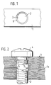
- FIG. 1 shows the top view of a core package
- FIG. 2 shows the side view of the core package from FIG. 1 with the fastening screw shown
- FIG. 3 shows a top view of a second core package
- FIG. 4 shows the side view of the core package from FIG. 3 with the fastening screw.
- Figures 1 and 2 are to be explained together since they only show the same subject from different views.
- the core package 1 can be seen made of sheet metal lamella coated with insulating varnish with a bore 2, with all of the remaining bores 2 having this diameter apart from at least one sheet metal lamella 1a.
- At least one lamella 1a has a smaller diameter 3. It is completely irrelevant at which point in the core package this lamella 1a with the smaller diameter 3 is arranged.
- the remaining sheet metal lamellae have a diameter of 2, this diameter being chosen so that a fastening screw 4 can easily be inserted into this bore 2 with play.
- the fastening screw 4 acts like a thread cutter and thus cuts a "partial thread" on the material protrusion 5 into the protruding sheet metal lamella 1 a, the insulating varnish being removed in this area of the sheet metal lamella 1 a and at the same time making a ground contact with the screw 4. So there is no additional effort when screwing the core package to a holder ground contact.
- the smaller diameter 3 of the one metal plate 1a is chosen so that the screw 4 can be screwed into it without damaging the thread.
- FIGS. 3 and 4 A further possibility of forming a sheet metal lamella is shown in FIGS. 3 and 4.
- the one sheet metal lamella 1b is punched with the same diameter as the rest of the core package 1, but with this one sheet metal lamella, a material residue protruding into the bore 2 in the form of a segment section according to FIG. 3 also remains here.
- This material protrusion 5 is selected so that the screw 4 removes the insulating varnish of the lamella 1a there without damaging the thread and makes a ground contact with a "partial thread".
- the other, differently shaped sheet metal lamella may have any other cross section of the opening, e.g. to choose a toothed lock washer. It is essential in all cases that the area of the machined material is smaller than that of the other lamellae, which are packed together to form the core package and the remaining opening is larger than the core cross section of the screw 4.
- a larger material protrusion 5 can also be selected in the bore 2, which protrudes in the screwing direction when the screw 4 is inserted and then presses into the screw thread with its edge freed from the insulating varnish.
- a rivet or a similar connecting element can also be used.
Landscapes
- Engineering & Computer Science (AREA)
- Power Engineering (AREA)
- Chemical & Material Sciences (AREA)
- Combustion & Propulsion (AREA)
- Mechanical Engineering (AREA)
- General Engineering & Computer Science (AREA)
- Bolts, Nuts, And Washers (AREA)
- Ignition Installations For Internal Combustion Engines (AREA)
- Manufacturing Cores, Coils, And Magnets (AREA)
- Connection Of Batteries Or Terminals (AREA)
Applications Claiming Priority (3)
| Application Number | Priority Date | Filing Date | Title |
|---|---|---|---|
| DE4119413A DE4119413C1 (enExample) | 1991-06-13 | 1991-06-13 | |
| DE4119413 | 1991-06-13 | ||
| PCT/DE1992/000330 WO1992022744A1 (de) | 1991-06-13 | 1992-04-24 | Spulenkern mit massekontaktierung |
Publications (2)
| Publication Number | Publication Date |
|---|---|
| EP0588804A1 EP0588804A1 (de) | 1994-03-30 |
| EP0588804B1 true EP0588804B1 (de) | 1995-10-11 |
Family
ID=6433795
Family Applications (1)
| Application Number | Title | Priority Date | Filing Date |
|---|---|---|---|
| EP92908833A Expired - Lifetime EP0588804B1 (de) | 1991-06-13 | 1992-04-24 | Spulenkern mit massekontaktierung |
Country Status (7)
| Country | Link |
|---|---|
| US (1) | US5398014A (enExample) |
| EP (1) | EP0588804B1 (enExample) |
| JP (1) | JPH06508240A (enExample) |
| AU (1) | AU651449B2 (enExample) |
| DE (2) | DE4119413C1 (enExample) |
| ES (1) | ES2079189T3 (enExample) |
| WO (1) | WO1992022744A1 (enExample) |
Families Citing this family (2)
| Publication number | Priority date | Publication date | Assignee | Title |
|---|---|---|---|---|
| DE102005028814A1 (de) * | 2005-06-22 | 2007-01-04 | Robert Bosch Gmbh | Zündspule für eine Brennkraftmaschine |
| WO2007124714A1 (de) * | 2006-05-01 | 2007-11-08 | Luk Lamellen Und Kupplungsbau Beteiligungs Kg | Freilauf mit dämpfung |
Family Cites Families (8)
| Publication number | Priority date | Publication date | Assignee | Title |
|---|---|---|---|---|
| US1727219A (en) * | 1927-09-09 | 1929-09-03 | Joachim B Scharf | Battery terminal clamp |
| FR673231A (fr) * | 1928-04-06 | 1930-01-13 | Thomson Houston Comp Francaise | Perfectionnements aux systèmes de fabrication des noyaux magnétiques pour appareils électriques |
| US2135937A (en) * | 1937-03-25 | 1938-11-08 | George B Gordon | Coupling for wires or electrical conductors |
| FR2321054A1 (fr) * | 1975-08-14 | 1977-03-11 | Sev Marchal | Bobine d'allumage |
| JPS5450733A (en) * | 1977-09-30 | 1979-04-20 | Hitachi Ltd | Ignitor for internal combustion engine |
| IT1101065B (it) * | 1978-11-13 | 1985-09-28 | Magneti Marelli Spa | Bobina d'accensione per autoveicoli |
| DE3528803A1 (de) * | 1985-08-10 | 1987-02-12 | Bosch Gmbh Robert | Zuendspule fuer mehrkerzige, verteilerlose zuendanlagen von brennkraftmaschinen, insbesondere fuer kraftfahrzeuge |
| FR2652195B1 (fr) * | 1989-09-15 | 1992-01-31 | Valeo Electronique | Bobine d'allumage, en particulier pour moteur a combustion interne de vehicule automobile. |
-
1991
- 1991-06-13 DE DE4119413A patent/DE4119413C1/de not_active Expired - Lifetime
-
1992
- 1992-04-24 JP JP4507960A patent/JPH06508240A/ja active Pending
- 1992-04-24 AU AU15740/92A patent/AU651449B2/en not_active Ceased
- 1992-04-24 ES ES92908833T patent/ES2079189T3/es not_active Expired - Lifetime
- 1992-04-24 US US08/162,069 patent/US5398014A/en not_active Expired - Fee Related
- 1992-04-24 WO PCT/DE1992/000330 patent/WO1992022744A1/de not_active Ceased
- 1992-04-24 DE DE59204007T patent/DE59204007D1/de not_active Expired - Fee Related
- 1992-04-24 EP EP92908833A patent/EP0588804B1/de not_active Expired - Lifetime
Also Published As
| Publication number | Publication date |
|---|---|
| EP0588804A1 (de) | 1994-03-30 |
| US5398014A (en) | 1995-03-14 |
| WO1992022744A1 (de) | 1992-12-23 |
| AU1574092A (en) | 1993-01-12 |
| DE59204007D1 (de) | 1995-11-16 |
| DE4119413C1 (enExample) | 1992-09-17 |
| AU651449B2 (en) | 1994-07-21 |
| ES2079189T3 (es) | 1996-01-01 |
| JPH06508240A (ja) | 1994-09-14 |
Similar Documents
| Publication | Publication Date | Title |
|---|---|---|
| DE3833329C2 (de) | Chipartige Mikrosicherung | |
| DE3784784T2 (de) | Elektrischer Verbinder für leichte Montage auf einer Leiterplatte und Ösen dafür. | |
| DE4412397A1 (de) | Vollständig zurückziehbare, unverlierbare Schraube | |
| DE3602673C2 (enExample) | ||
| EP0134540A1 (de) | Hochfrequenzdichte Abschirmung von Flächenteilen | |
| EP0559666B1 (de) | Polkern | |
| DE19842591C1 (de) | Verfahren zur Befestigung einer Baugruppe mit mindestens einer an dieser Baugruppe vormontierten Befestigungsschraube an einem Träger mit einer zugeordneten Öffnung sowie entsprechende Sicherungskappe | |
| DE69423658T2 (de) | Anschlussblock | |
| EP0025472B1 (de) | Schaltschranktürverschluss-Befestigungsmutter zur Befestigung von aus Metall bestehenden Verschlüssen für Schaltschranktüren | |
| DE2907417C2 (enExample) | ||
| EP1003243B1 (de) | Verfahren zur Herstellung einer elektrischen Verbindung zu einem Blechteil und Zusammenbauteil | |
| DE69002255T2 (de) | Mutterbefestigungsstruktur für ein Kunstharzgehäuse. | |
| DE4428699B4 (de) | Elektrische Verbindungsanordnung | |
| DE3918780A1 (de) | Beschleunigungsaufnehmer | |
| EP0588804B1 (de) | Spulenkern mit massekontaktierung | |
| DE2601731A1 (de) | Selbstsicherndes befestigungsmittel | |
| EP0545158B1 (de) | Schraubeinrichtung | |
| DE3139590A1 (de) | Vorichtung zum befestigen eines bandes an einem uhrengehaeuse | |
| DE69403612T2 (de) | Uhr mit einer Vorrichtung zur Befestigung eines abnehmbaren Elementes an einen Träger und Verfahren zum Befestigen dieses Elementes an diesen Träger | |
| DE3517933A1 (de) | Schrankschloss mit versenktem schliesskopf | |
| DE29716019U1 (de) | Kabel-Stecker-Durchführung für ein Gehäuse | |
| EP0653571B1 (de) | Blechmutter zur Blindbefestigung | |
| DE2041110A1 (de) | Befestigungsvorrichtung zum Befestigen der aeusseren Enden zweier Spiralfedern in zeithaltenden Instrumenten | |
| DE2852141A1 (de) | Elektrischer kontakt | |
| DE69610034T2 (de) | Wechselstromgenerator für ein Kraftfahrzeug mit einer Bürstentragplatte mit umgossenem Entstörkondensator |
Legal Events
| Date | Code | Title | Description |
|---|---|---|---|
| PUAI | Public reference made under article 153(3) epc to a published international application that has entered the european phase |
Free format text: ORIGINAL CODE: 0009012 |
|
| 17P | Request for examination filed |
Effective date: 19931110 |
|
| AK | Designated contracting states |
Kind code of ref document: A1 Designated state(s): DE ES FR IT |
|
| 17Q | First examination report despatched |
Effective date: 19950309 |
|
| GRAA | (expected) grant |
Free format text: ORIGINAL CODE: 0009210 |
|
| AK | Designated contracting states |
Kind code of ref document: B1 Designated state(s): DE ES FR IT |
|
| ET | Fr: translation filed | ||
| REF | Corresponds to: |
Ref document number: 59204007 Country of ref document: DE Date of ref document: 19951116 |
|
| REG | Reference to a national code |
Ref country code: ES Ref legal event code: FG2A Ref document number: 2079189 Country of ref document: ES Kind code of ref document: T3 |
|
| ITF | It: translation for a ep patent filed | ||
| PLBE | No opposition filed within time limit |
Free format text: ORIGINAL CODE: 0009261 |
|
| 26N | No opposition filed | ||
| PGFP | Annual fee paid to national office [announced via postgrant information from national office to epo] |
Ref country code: FR Payment date: 19980420 Year of fee payment: 7 |
|
| PGFP | Annual fee paid to national office [announced via postgrant information from national office to epo] |
Ref country code: ES Payment date: 19980430 Year of fee payment: 7 |
|
| PGFP | Annual fee paid to national office [announced via postgrant information from national office to epo] |
Ref country code: DE Payment date: 19980619 Year of fee payment: 7 |
|
| PG25 | Lapsed in a contracting state [announced via postgrant information from national office to epo] |
Ref country code: ES Free format text: LAPSE BECAUSE OF NON-PAYMENT OF DUE FEES Effective date: 19990426 |
|
| PG25 | Lapsed in a contracting state [announced via postgrant information from national office to epo] |
Ref country code: FR Free format text: LAPSE BECAUSE OF NON-PAYMENT OF DUE FEES Effective date: 19991231 |
|
| REG | Reference to a national code |
Ref country code: FR Ref legal event code: ST |
|
| PG25 | Lapsed in a contracting state [announced via postgrant information from national office to epo] |
Ref country code: DE Free format text: LAPSE BECAUSE OF NON-PAYMENT OF DUE FEES Effective date: 20000201 |
|
| REG | Reference to a national code |
Ref country code: ES Ref legal event code: FD2A Effective date: 20010503 |
|
| PG25 | Lapsed in a contracting state [announced via postgrant information from national office to epo] |
Ref country code: IT Free format text: LAPSE BECAUSE OF NON-PAYMENT OF DUE FEES;WARNING: LAPSES OF ITALIAN PATENTS WITH EFFECTIVE DATE BEFORE 2007 MAY HAVE OCCURRED AT ANY TIME BEFORE 2007. THE CORRECT EFFECTIVE DATE MAY BE DIFFERENT FROM THE ONE RECORDED. Effective date: 20050424 |