EP0588668A2 - Codage et décodage de signaux vidéo digitaux ayant des images repetées avec des trames provenant de differents champs issus de films - Google Patents
Codage et décodage de signaux vidéo digitaux ayant des images repetées avec des trames provenant de differents champs issus de films Download PDFInfo
- Publication number
- EP0588668A2 EP0588668A2 EP19930307404 EP93307404A EP0588668A2 EP 0588668 A2 EP0588668 A2 EP 0588668A2 EP 19930307404 EP19930307404 EP 19930307404 EP 93307404 A EP93307404 A EP 93307404A EP 0588668 A2 EP0588668 A2 EP 0588668A2
- Authority
- EP
- European Patent Office
- Prior art keywords
- picture
- signal
- video signal
- coded
- field
- Prior art date
- Legal status (The legal status is an assumption and is not a legal conclusion. Google has not performed a legal analysis and makes no representation as to the accuracy of the status listed.)
- Granted
Links
Images


Classifications
-
- H—ELECTRICITY
- H04—ELECTRIC COMMUNICATION TECHNIQUE
- H04N—PICTORIAL COMMUNICATION, e.g. TELEVISION
- H04N7/00—Television systems
- H04N7/24—Systems for the transmission of television signals using pulse code modulation
- H04N7/52—Systems for transmission of a pulse code modulated video signal with one or more other pulse code modulated signals, e.g. an audio signal or a synchronizing signal
-
- G—PHYSICS
- G11—INFORMATION STORAGE
- G11B—INFORMATION STORAGE BASED ON RELATIVE MOVEMENT BETWEEN RECORD CARRIER AND TRANSDUCER
- G11B20/00—Signal processing not specific to the method of recording or reproducing; Circuits therefor
-
- H—ELECTRICITY
- H04—ELECTRIC COMMUNICATION TECHNIQUE
- H04N—PICTORIAL COMMUNICATION, e.g. TELEVISION
- H04N19/00—Methods or arrangements for coding, decoding, compressing or decompressing digital video signals
-
- H—ELECTRICITY
- H04—ELECTRIC COMMUNICATION TECHNIQUE
- H04N—PICTORIAL COMMUNICATION, e.g. TELEVISION
- H04N19/00—Methods or arrangements for coding, decoding, compressing or decompressing digital video signals
- H04N19/10—Methods or arrangements for coding, decoding, compressing or decompressing digital video signals using adaptive coding
- H04N19/102—Methods or arrangements for coding, decoding, compressing or decompressing digital video signals using adaptive coding characterised by the element, parameter or selection affected or controlled by the adaptive coding
- H04N19/103—Selection of coding mode or of prediction mode
- H04N19/105—Selection of the reference unit for prediction within a chosen coding or prediction mode, e.g. adaptive choice of position and number of pixels used for prediction
-
- H—ELECTRICITY
- H04—ELECTRIC COMMUNICATION TECHNIQUE
- H04N—PICTORIAL COMMUNICATION, e.g. TELEVISION
- H04N19/00—Methods or arrangements for coding, decoding, compressing or decompressing digital video signals
- H04N19/10—Methods or arrangements for coding, decoding, compressing or decompressing digital video signals using adaptive coding
- H04N19/102—Methods or arrangements for coding, decoding, compressing or decompressing digital video signals using adaptive coding characterised by the element, parameter or selection affected or controlled by the adaptive coding
- H04N19/103—Selection of coding mode or of prediction mode
- H04N19/112—Selection of coding mode or of prediction mode according to a given display mode, e.g. for interlaced or progressive display mode
-
- H—ELECTRICITY
- H04—ELECTRIC COMMUNICATION TECHNIQUE
- H04N—PICTORIAL COMMUNICATION, e.g. TELEVISION
- H04N19/00—Methods or arrangements for coding, decoding, compressing or decompressing digital video signals
- H04N19/10—Methods or arrangements for coding, decoding, compressing or decompressing digital video signals using adaptive coding
- H04N19/102—Methods or arrangements for coding, decoding, compressing or decompressing digital video signals using adaptive coding characterised by the element, parameter or selection affected or controlled by the adaptive coding
- H04N19/132—Sampling, masking or truncation of coding units, e.g. adaptive resampling, frame skipping, frame interpolation or high-frequency transform coefficient masking
-
- H—ELECTRICITY
- H04—ELECTRIC COMMUNICATION TECHNIQUE
- H04N—PICTORIAL COMMUNICATION, e.g. TELEVISION
- H04N19/00—Methods or arrangements for coding, decoding, compressing or decompressing digital video signals
- H04N19/10—Methods or arrangements for coding, decoding, compressing or decompressing digital video signals using adaptive coding
- H04N19/134—Methods or arrangements for coding, decoding, compressing or decompressing digital video signals using adaptive coding characterised by the element, parameter or criterion affecting or controlling the adaptive coding
- H04N19/136—Incoming video signal characteristics or properties
- H04N19/137—Motion inside a coding unit, e.g. average field, frame or block difference
-
- H—ELECTRICITY
- H04—ELECTRIC COMMUNICATION TECHNIQUE
- H04N—PICTORIAL COMMUNICATION, e.g. TELEVISION
- H04N19/00—Methods or arrangements for coding, decoding, compressing or decompressing digital video signals
- H04N19/10—Methods or arrangements for coding, decoding, compressing or decompressing digital video signals using adaptive coding
- H04N19/169—Methods or arrangements for coding, decoding, compressing or decompressing digital video signals using adaptive coding characterised by the coding unit, i.e. the structural portion or semantic portion of the video signal being the object or the subject of the adaptive coding
- H04N19/17—Methods or arrangements for coding, decoding, compressing or decompressing digital video signals using adaptive coding characterised by the coding unit, i.e. the structural portion or semantic portion of the video signal being the object or the subject of the adaptive coding the unit being an image region, e.g. an object
- H04N19/172—Methods or arrangements for coding, decoding, compressing or decompressing digital video signals using adaptive coding characterised by the coding unit, i.e. the structural portion or semantic portion of the video signal being the object or the subject of the adaptive coding the unit being an image region, e.g. an object the region being a picture, frame or field
-
- H—ELECTRICITY
- H04—ELECTRIC COMMUNICATION TECHNIQUE
- H04N—PICTORIAL COMMUNICATION, e.g. TELEVISION
- H04N19/00—Methods or arrangements for coding, decoding, compressing or decompressing digital video signals
- H04N19/10—Methods or arrangements for coding, decoding, compressing or decompressing digital video signals using adaptive coding
- H04N19/169—Methods or arrangements for coding, decoding, compressing or decompressing digital video signals using adaptive coding characterised by the coding unit, i.e. the structural portion or semantic portion of the video signal being the object or the subject of the adaptive coding
- H04N19/17—Methods or arrangements for coding, decoding, compressing or decompressing digital video signals using adaptive coding characterised by the coding unit, i.e. the structural portion or semantic portion of the video signal being the object or the subject of the adaptive coding the unit being an image region, e.g. an object
- H04N19/176—Methods or arrangements for coding, decoding, compressing or decompressing digital video signals using adaptive coding characterised by the coding unit, i.e. the structural portion or semantic portion of the video signal being the object or the subject of the adaptive coding the unit being an image region, e.g. an object the region being a block, e.g. a macroblock
-
- H—ELECTRICITY
- H04—ELECTRIC COMMUNICATION TECHNIQUE
- H04N—PICTORIAL COMMUNICATION, e.g. TELEVISION
- H04N19/00—Methods or arrangements for coding, decoding, compressing or decompressing digital video signals
- H04N19/46—Embedding additional information in the video signal during the compression process
-
- H—ELECTRICITY
- H04—ELECTRIC COMMUNICATION TECHNIQUE
- H04N—PICTORIAL COMMUNICATION, e.g. TELEVISION
- H04N19/00—Methods or arrangements for coding, decoding, compressing or decompressing digital video signals
- H04N19/50—Methods or arrangements for coding, decoding, compressing or decompressing digital video signals using predictive coding
- H04N19/503—Methods or arrangements for coding, decoding, compressing or decompressing digital video signals using predictive coding involving temporal prediction
- H04N19/51—Motion estimation or motion compensation
- H04N19/577—Motion compensation with bidirectional frame interpolation, i.e. using B-pictures
-
- H—ELECTRICITY
- H04—ELECTRIC COMMUNICATION TECHNIQUE
- H04N—PICTORIAL COMMUNICATION, e.g. TELEVISION
- H04N19/00—Methods or arrangements for coding, decoding, compressing or decompressing digital video signals
- H04N19/50—Methods or arrangements for coding, decoding, compressing or decompressing digital video signals using predictive coding
- H04N19/587—Methods or arrangements for coding, decoding, compressing or decompressing digital video signals using predictive coding involving temporal sub-sampling or interpolation, e.g. decimation or subsequent interpolation of pictures in a video sequence
-
- H—ELECTRICITY
- H04—ELECTRIC COMMUNICATION TECHNIQUE
- H04N—PICTORIAL COMMUNICATION, e.g. TELEVISION
- H04N19/00—Methods or arrangements for coding, decoding, compressing or decompressing digital video signals
- H04N19/50—Methods or arrangements for coding, decoding, compressing or decompressing digital video signals using predictive coding
- H04N19/59—Methods or arrangements for coding, decoding, compressing or decompressing digital video signals using predictive coding involving spatial sub-sampling or interpolation, e.g. alteration of picture size or resolution
-
- H—ELECTRICITY
- H04—ELECTRIC COMMUNICATION TECHNIQUE
- H04N—PICTORIAL COMMUNICATION, e.g. TELEVISION
- H04N19/00—Methods or arrangements for coding, decoding, compressing or decompressing digital video signals
- H04N19/60—Methods or arrangements for coding, decoding, compressing or decompressing digital video signals using transform coding
- H04N19/61—Methods or arrangements for coding, decoding, compressing or decompressing digital video signals using transform coding in combination with predictive coding
-
- H—ELECTRICITY
- H04—ELECTRIC COMMUNICATION TECHNIQUE
- H04N—PICTORIAL COMMUNICATION, e.g. TELEVISION
- H04N19/00—Methods or arrangements for coding, decoding, compressing or decompressing digital video signals
- H04N19/85—Methods or arrangements for coding, decoding, compressing or decompressing digital video signals using pre-processing or post-processing specially adapted for video compression
-
- H—ELECTRICITY
- H04—ELECTRIC COMMUNICATION TECHNIQUE
- H04N—PICTORIAL COMMUNICATION, e.g. TELEVISION
- H04N7/00—Television systems
- H04N7/01—Conversion of standards, e.g. involving analogue television standards or digital television standards processed at pixel level
- H04N7/0112—Conversion of standards, e.g. involving analogue television standards or digital television standards processed at pixel level one of the standards corresponding to a cinematograph film standard
-
- H—ELECTRICITY
- H04—ELECTRIC COMMUNICATION TECHNIQUE
- H04N—PICTORIAL COMMUNICATION, e.g. TELEVISION
- H04N19/00—Methods or arrangements for coding, decoding, compressing or decompressing digital video signals
- H04N19/10—Methods or arrangements for coding, decoding, compressing or decompressing digital video signals using adaptive coding
- H04N19/134—Methods or arrangements for coding, decoding, compressing or decompressing digital video signals using adaptive coding characterised by the element, parameter or criterion affecting or controlling the adaptive coding
- H04N19/146—Data rate or code amount at the encoder output
- H04N19/152—Data rate or code amount at the encoder output by measuring the fullness of the transmission buffer
Definitions
- This invention relates to an apparatus and method for coding a video signal derived from a motion picture film source in which the video signal includes duplicate pictures, and includes frames consisting of fields originating from different frames of the motion picture film source.
- the Motion Picture Experts Group (MPEG) standard is representative of a standard for compressing digital video signals for transmission or storage.
- the standard was discussed by ISO-IEC/JTC1/SC2/WG11 and has been proposed as a draft standard.
- the standard stipulates a hybrid compression method combining motion compensated prediction coding with discrete cosine transform (DCT) coding.
- DCT discrete cosine transform
- the first compression technique takes advantage of the correlation of video signals in the time domain.
- the video signal representing the current picture (a frame or a field) is predicted from the decoded and reproduced (reconstituted) video signal representing a reference picture, which is a picture that is earlier or later than the current picture. Only the motion prediction errors between the video signal representing the current picture and the reconstituted video signal representing the reference picture are transmitted or stored. This significantly reduces the amount of digital video signal required to represent the current picture.
- the second compression technique takes advantage of the intra-picture, two-dimensional correlation of a video signal.
- DCT coding takes advantage of the intra-picture, two-dimensional correlation of a video signal.
- signal power is concentrated in specific frequency components. Consequently, quantizing bits need only be allocated to the DCT coefficients in the region in which the signal power is concentrated. This further reduces the quantity of digital video signal required to represent the picture. For example, in a region in which the image has little detail, and in which the video signal is thus highly correlated, the DCT coefficients are concentrated at low frequencies. In that case, only the DCT coefficients in the low-frequency region of the distribution pattern are quantized to reduce the quantity of the digital video signal.
- the coding techniques of the MPEG standard are basically intended for use with interlaced video signals, problems arise then they are applied without modification to progressive (non-interlaced) video signals.
- the compression ratio can be impaired when the MPEG techniques are applied to progressive video signals.
- a motion picture consists of a sequence of still pictures reproduced in succession, normally 24 pictures per second.
- a motion picture film source e.g., a motion picture film or a 24-frame video signal, represents each picture of the motion picture as a full frame with a frame rate of 24 Hz, whereas an interlaced video signal represents each picture of the motion picture as two consecutive fields, each field representing half of the picture and being displaced from one the other by one line.
- An NTSC interlaced video signal has a field rate of 60 Hz.
- deriving an interlaced video signal with a field rate of 60 Hz from a motion picture film source with a frame rate of 24 Hz requires a conversion between the number of frames per second of the film source and the number of fields per second in the video signal.
- a motion picture film source with a 24 Hz frame rate is commonly converted to an interlaced video signal with a 60 Hz field rate, such as an NTSC video signal, by a technique known as 2-3 pull-down.
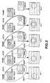
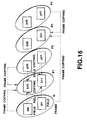
- Figure 1 illustrates how 2-3 pull-down works.
- the 2-3 pull-down process involves a repetitive sequence of deriving two fields of the video signal from the first of every two consecutive frames of the motion picture film source, and deriving three fields of the video signal from the second of the two consecutive frames of the film source.
- frames 1500 and 1501 are consecutive frames of a motion picture film source with a frame rate of 24 Hz.
- each film source frame is divided into an odd field, indicated by a solid line, and an even field, indicated by a broken line.
- the video field 1502 an odd field
- the video field 1503 an even field.
- three fields of the video signal are derived from the second film source frame 1501.
- the video field 1504, an odd field is first derived, followed by the video field 1505, an even field, followed by the video field 1506, another odd field.
- the two odd fields 1504 and 1506 are identical to one another. This process is repeated for the other two film source frames 1508 and 1509 from which the video fields 1510 through 1514 are derived.
- an even field 1510 is derived first from the film source frame 1508, and that two even fields 1512 and 1514 are derived from the film source frame 1509.
- a sequence of ten fields of the video signal is derived from a sequence of four frames of the motion picture film source, after which the sequence is repeated.
- Figure 2 shows the result of combining into frames consecutive pairs of fields of the interlaced video signal derived by the process shown in Figure 1.
- the video fields 1600 and 1601 are derived from the same film source frame.
- Video fields 1602 and 1603 are also derived from the same film source frame.
- the video frame 1607, produced by combining the video fields 1600 and 1601, and the video frame 1608, produced by combining the video fields 1602 and 1603, are each derived from the same film source frame.
- the video frame 1609, produced by combining the consecutive video fields 1604 and 1605 is derived from two different film source frames.
- a first aspect of the invention provides a method for coding an input video signal to provide a coded signal.
- the input video signal has a field rate of 60 Hz and is derived from a motion picture film source using 2-3 pulldown.
- first frames consisting of fields derived from different frames of the motion picture film source, are detected in the input video signal.
- the input video signal is predictively coded to provide the coded signal by using second frames as reference pictures.
- Second frames are frames of the input video signal other than the first frames detected in the detecting step.
- the method may detect the first frames by detecting duplicate fields in the input video signal, the method may additionally eliminate the duplicate fields from the input video signal, and include in the coded signal a skip-picture flag in lieu of each eliminated duplicate field, and a reference picture code identifying a field to be copied to provide each eliminated duplicated field.
- a second aspect of the invention provides a method for coding an input video signal to provide a coded signal, in which duplicate pictures are detected in the input video signal, and each duplicate picture is eliminated from the input video signal to provide an encoder input signal.
- the encoder input signal is predictively coded using plural predictive coding methods to provide the coded signal.
- a skip-picture flag is included in the coded signal in lieu of each eliminated duplicate picture, and a reference picture code identifying a field to be copied to provide each eliminated duplicate picture is also included in the coded signal.
- a third aspect of the invention provides a method for decoding a coded signal to provide an output video signal, in which the coded signal is derived by applying predictive coding to an input video signal having a field rate of 60 Hz and being derived from a motion picture film source using 2-3 pulldown.
- the predictive coding is applied such that frames of the input video signal consisting of fields derived from different frames of the motion picture source are coded using field mode coding, and all other frames of the input video signal are coded using frame mode coding.
- the coded video signal includes a processing mode flag signal indicating a coding mode for each frame.
- the processing mode flag for each frame is extracted from the coding signal, and inverse predictive coding is applied to the coded signal to provide the output video signal.
- the inverse predictive coding for each frame has the coding mode indicated by the processing mode flag extracted from the coded signal.
- a fourth aspect of the present invention provides a method for decoding a coded signal to provide an output video signal.
- the coded signal is generated by eliminating duplicate pictures from an input video signal.
- the coded signal includes, in lieu of each eliminated duplicate picture, a skip picture flag, and a reference picture code identifying a picture to be copied to provide the eliminated duplicate picture.
- the skip picture flag and the reference picture code are extracted from the coded video signal.
- Inverse predictive coding is applied to the coded signal to provide the output video signal.
- the picture indicated by the reference picture code is copied in response to the skip picture flag to restore an eliminated duplicate picture to the output video signal.
- a fifth aspect of the invention provides a recording, comprising a recording medium and a recording signal recorded in the recording medium.
- the recording signal includes a video input signal derived from a motion picture film source and coded by predictive coding using as reference pictures only frames of the input video signal that consist of fields derived from the same frame of the motion picture source.
- a sixth aspect of the invention provides a recording comprising a recording medium; and a recording signal recorded in the recording medium, wherein the recording signal includes a coded video input signal wherefrom duplicate pictures are eliminated, and also includes in lieu of each eliminated duplicate picture, a skip picture flag and a picture reference code identifying a field to be copied to restore the eliminated duplicate picture.
- a seventh aspect of the invention provides an apparatus for coding an input video signal to provide a coded signal.
- the input video signal has a field rate of 60 Hz and is derived from a motion picture film source using 2-3 pulldown.
- the apparatus comprises a circuit that detects first frames in the input video signal. First frames consist of fields derived from different frames of the motion picture film source.
- the apparatus also comprises a predictive coding circuit that provides the coded signal by predictively coding the input video signal.
- the predictive coding circuit uses second frames as reference pictures. Second frames are frames of the input video signal other than the first frames detected by the detecting circuit.
- a circuit eliminates each detected duplicate picture from the input video signal to provide an encoder input signal.
- a predictive coding circuit predictively codes the encoder input signal using plural predictive coding methods to provide the coded signal.
- a circuit includes a skip-picture flag in the coded signal in lieu of each eliminated duplicate picture, and additionally includes in the coded signal a reference picture code identifying a field to be copied to provide each eliminated duplicate picture.
- a ninth aspect of the invention provides an apparatus for decoding a coded signal to provide an output video signal.
- the coded signal is derived by applying predictive coding to an input video signal having a field rate of 60 Hz.
- the input video signal is derived from a motion picture film source by 2-3 pulldown.
- the predictive coding is applied such that frames of the input video signal consisting of fields derived from different frames of the motion picture source are coded using field mode coding, and all other frames of the input video signal are coded using frame mode coding.
- the coded video signal includes a processing mode flag signal indicating a coding mode for each frame.
- the apparatus comprises an extracting circuit that extracts the processing mode flag for each frame from the coded signal.
- the apparatus additionally comprises a circuit that applies inverse predictive coding to the coded signal to provide the output video signal.
- the inverse predictive coding applied to each frame has the coding mode indicated by the processing mode flag extracted by the extracting circuit.
- a tenth aspect of the invention provides a decoding apparatus for decoding a coded signal to provide an output video signal.
- the coded signal is generated by eliminating duplicate pictures from an input video signal, and includes a skip-picture flag in lieu of each eliminated duplicate picture, and a reference picture code identifying a field to be copied to provide the eliminated duplicate picture.
- the decoding apparatus comprises a circuit that extracts the skip picture flag and the reference picture code from the coded signal and a circuit that applies inverse predictive coding to the coded signal to provide the output video signal.
- the apparatus additionally comprises a circuit that copies, in response to the skip picture flag, the picture indicated by the reference picture code to restore an eliminated duplicate field to the output video signal.
- An eleventh aspect of the invention provides a system for deriving a recording signal from an input video signal and for reproducing the recorded signal to provide an output video signal.
- the recording signal has a bit rate substantially lower than the input video signal and the output video signal.
- the input video signal and the output video signal has a field rate of 60 Hz, and the input video signal is derived from a motion picture film source using 2-3 pulldown.
- the system comprises an encoding apparatus and a decoding apparatus.
- the encoding apparatus comprises a circuit that detects first frames in the input video signal. First frames consist of fields derived from different frames of the motion picture film source.
- the encoding also includes a predictive coding circuit that predictively codes the video input signal to provide the recording signal,
- the predictive coding circuit codes each first frame using field mode coding and codes each second frame using frame mode coding.
- a second frame is a frame of the input video signal other than a first frame detected by the detecting circuit.
- the encoding apparatus comprises a circuit that includes in the recording signal a processing mode flag indicating a coding mode for each frame of the input video signal.
- the decoding apparatus comprises a circuit that extracts the processing mode flag for each frame from the recording signal.
- the decoding apparatus also includes a circuit that applies inverse predictive coding to the recording signal to provide the output video signal.
- the inverse predictive coding applied to each frame has the coding mode indicated by the processing mode flag extracted by the extracting circuit.
- a twelfth aspect of the invention provides a system for deriving a recording signal from an input video signal and for reproducing the recorded signal to provide an output video signal.
- the recording signal has a bit rate substantially lower than the input video signal and the output video signal.
- the system comprises an encoding apparatus and a decoding apparatus.
- the encoding apparatus comprises a circuit that detects duplicate pictures in the input video signal and a circuit that eliminates each duplicate picture from the input video signal to provide an encoder input signal.
- a predictive coding circuit predictively codes the encoder input signal using plural predictive coding methods to provide the recording signal.
- the encoding apparatus additionally comprises a circuit that includes a skip-picture flag in the recording signal in lieu of each eliminated duplicate picture, and that additionally includes in the recording signal a reference picture code identifying a field to be copied to provide each eliminated duplicate picture.
- the decoding apparatus comprises a circuit that extracts the skip picture flag and the reference picture code from the recording signal, and a circuit that applies inverse predictive coding to the recording signal to provide the output video signal.
- the decoding apparatus comprises a circuit that copies, in response to the skip picture flag, the picture indicated by the reference picture code to restore an eliminated duplicate field to the output video signal.
- FIG. 3 shows the coding apparatus 100 and the decoding apparatus 101 that form the video signal processing apparatus according to the first embodiment of the present invention.
- the coding apparatus 100 embodying the first aspect of the present invention includes the 2-3 pull-don detection circuit 102 for detecting duplicate fields in the coder input signal VI, a video signal having a field rate of 60 Hz that is derived from a motion picture film source by 2-3 pull-down.
- the 2-3 pull-down detection circuit 102 generates the duplication detection signal DDS, and delays the coder input signal VI by a predetermined processing time to generate the video signal VI1.
- the coding apparatus 101 also includes the processing mode selecting circuit 103 which generates, in response to the duplication detection signal DDS, the overflow signal OVF from the variable-length coder 106, and the video signal VI1, the following control signals and flags for each picture in the coder input signal VI: the skip picture flag SPC that indicates whether the picture is a duplicate picture; the processing unit flag PUC that indicates whether the picture is to be coded using field-mode or frame-mode coding; the prediction mode code PMC, which indicates the prediction mode for coding the picture, i.e., whether the picture is to be coded as an I-picture (no prediction), a P-picture (forward prediction from an earlier reference picture), or a B-picture (backward prediction from a later reference picture, linear prediction between earlier and later reference pictures, or forward prediction from an earlier reference picture); and the reference picture code RFC that indicates, when the picture is a skip picture, the picture (field or frame) that will be used as the reference picture for reproducing the skip picture.
- the processing mode selecting circuit 103 additionally delays the video signal VI1 by a predetermined processing time to generate the video signal VI2.
- the coding apparatus 100 also includes the scan converter 104 that converts two interlaced fields of the video signal VI2 into a progressive frame when the processing unit flag PUC indicates that the picture is to be coded using frame mode coding. Otherwise, when the processing unit flag PUC indicates that the picture is to be coded using field mode coding, the scan converter 104 supplies the two fields of the video signal VI2 unmodified as two fields of the video signal VI3.
- the field sequence exchange circuit 105 receives the video signal VI3 and changes the picture sequence of the video signal VI3 to the sequence required by the encoder 106 in response to the skip picture flag SPC, the processing unit flag PUC, the prediction mode code PMC, and the reference picture code RFC generated by the processing mode selecting circuit 103.
- the field sequence exchange circuit 105 provides the resulting sequence-exchanged video signal as the video signal VI4.
- the encoder 106 codes the video signal VI4 in response to the skip picture flag SPC, the prediction mode code PMC, and the reference picture code RFC generated by the processing mode selecting circuit 103, to generate the coded signal VC1.
- the error correction coding (ECC) circuit 107 appends error correction codes to the encoded signal VC1 to generate the encoded signal VC2, which passes to the modulating circuit 108 where it is modulated to provide the recording signal VC3 for recording on the recording medium 109.
- the decoding apparatus 101 of the first embodiment of the invention includes the demodulating circuit 111 for demodulating the signal VD1 reproduced from the recording medium 110 to provide the decoded signal VD2.
- the recording medium 110 is the same as, or is derived from, the recording medium 109.
- the decoded signal VD2 passes to the error correction code decoder (ECC decoder) 112, which detects and corrects errors in the decoded signal VD2 to provide the decoder input signal VD3.
- ECC decoder error correction code decoder
- the decoder 113 extracts from the decoder input signal VD3 the skip picture flag SPC, the processing unit flag PUC, the prediction mode code PMC, and the reference picture code RFC that were generated by the processing mode selecting circuit 103, and provides these flags and codes as the skip picture flag SPD, the processing unit flag PUD, the prediction mode code PMD, and the reference picture code RFD, respectively.
- the decoder 113 also decodes the coded picture signals in the decoder input signal VD3 in response to these flags and codes to provide the decoder output signal VO1.
- the scan converting circuit 114 converts one frame of the decoder output signal VO1 into two fields of the video signal VO2 when the processing unit flag PUD from the decoder 113 indicates that the frame was processed in frame mode. Otherwise, when the processing unit flag PUD from the decoder 113 indicates that the frame was processed in field mode, the scan converting circuit 114 supplies the video signal VO1 unmodified as two fields of the video signal VO2.
- the sequence exchange circuit 115 restores the picture sequence of the video signal VO2 to the picture sequence of the coder input signal VI to provide the decoder apparatus output signal VO.
- the sequence exchange circuit 115 changes the picture sequence in response to the skip picture flag SPD, the processing unit flag PUD, the prediction mode code PMD, and the reference picture code RFD from the decoder 113.
- the resulting decoding apparatus output signal VO is a video signal that is suitable for display on a monitor after conversion to an analog signal.
- the coding apparatus 100 according to the first embodiment of the invention will now be described in detail.
- the coder input signal VI a video signal with a 60 Hz field rate
- the 2-3 pulldown detection circuit 102 detects each duplicate field in the coder input signal VI, and generates the duplication detection signal DDS in response thereto.
- the 2-3 pull-down detection circuit 102 also delays the coder input signal VI by a time corresponding to the processing delay of the 2-3 pulldown detection circuit before feeding the delayed coder input signal VI out as the video signal VI1.
- the processing mode selecting circuit 103 derives four signals for each picture in the video signal VI1 in response to the video signal VI1 and the duplication detection signal DDS. These signals are; the skip picture flag SPC, which indicates whether the picture is a duplicate picture (field or frame). A duplicate picture is one with little or no temporal change relative to another picture; the processing unit flag PUC, which indicates whether the picture is to be coded using field-mode coding or frame-mode coding; the prediction mode code PMC, which indicates the prediction mode for coding the picture, i.e., whether the picture is to be coded as an I-picture (no prediction), a P-picture (forward prediction from an earlier reference picture), or a B-picture (backward prediction from a later reference picture, linear prediction between earlier and later reference pictures, or forward prediction from an earlier reference picture); and the reference picture code RFC, which indicates, when the picture is a skip picture, the picture to be used as the reference picture for reproducing the skip picture.
- the skip picture flag SPC which indicates whether the picture is
- the processing mode selecting circuit 103 delays the video signal VI1 by a time equal to the processing time of the processing mode selecting circuit before feeding the video signal VI1 out as the video signal VI2.
- the scan converting circuit 104 interleaves the two fields of the field-based video signal VI2 into a single frame, which it feeds out as a picture of the video signal VI3. If the processing unit flag PUC indicates that a picture will be coded in field mode, the processing mode selection circuit feeds the two fields of the video signal VI2 out unchanged as two fields of the video signal VI3.
- the sequence exchange circuit 105 changes the picture (field or frame) sequence of the video signal VI3 to provide the encoder input signal VI4 with the picture sequence required by the encoder 106.
- the sequence exchange circuit changes the picture sequence in response to the skip picture flag SPC, the processing unit flag PUC, the prediction mode code PMC, and the reference picture code RFC.
- the encoder 106 encodes the encoder input signal VI4 in response to the skip picture flag SPC, the processing unit flag PUC, the prediction mode code PMC, and the reference picture code RFC, received from the processing mode selecting circuit 103, and provides the encoder output signal VC1.
- the ECC circuit 107 appends error correction codes to the encoder output signal VC1 to provide the encoded signal VC2, which the modulating circuit 108 modulates to provide the recording signal VC3 for recording by a recording apparatus, not shown, on the recording medium 109.
- the decoding apparatus 101 will now be described in detail.
- the recording signal VD1 read out from the recording medium 110, is demodulated by the demodulating circuit 111 to provide the demodulated signal VD2.
- the ECC decoding circuit 112 applies error detection and correction to the demodulated signal VD2 to generate the decoder input signal VD3.
- the decoder input signal VD3 is fed into the decoder 113, which extracts from the signal VD3 the skip picture flag SPC, the processing unit flag PUC, the prediction mode code PMC, and the reference picture code RFC that were generated by the processing mode selecting circuit 103, and provides them as the skip picture flag SPD, the processing unit flag PUD, the prediction mode code PMD, and the reference picture code RFD.
- the decoder 113 also decodes the coded picture signals in the decoder input signal VD3 to provide the decoder output signal VO1.
- the scan converting circuit 114 converts one frame of the video signal VO1 into two fields of the video signal VO2 when the processing unit flag PUD from the decoder 113 indicates that the frame was processed in frame mode. Otherwise, the scan converting circuit 114 supplies two fields of the video signal VO1 without modification as two fields of the video signal VO2.
- the sequence exchange circuit 115 restores the picture sequence of the video signal VO2 to the picture sequence of the coder input signal VI to provide the decoder apparatus output signal VO.
- the sequence exchange circuit 115 changes the picture sequence in response to the skip picture flag SPD, the processing unit flag PUD, prediction mode code PMD, and the reference picture code RFD from the decoder 113. This permits the recording signal to be reproduced from the recording medium 110.
- the coder input signal VI a video signal with a field rate of 60 Hz
- the selector 207 which extracts the even fields from the coder input signal to provide the video signal VP2.
- the video signal VP2 is fed into the subtractor 203.
- the coder input signal VI is delayed by two field periods by the field delay circuits 201 and 202 and is also fed to the subtractor 203.
- the subtractor 203 calculates a pixel-by-pixel difference between the coder input signal delayed by two fields VP1, and the video signal VP2 from the selector 207, and feeds the resulting difference signal VP3 to the absolute value circuit 204.
- the absolute value circuit 204 determines the absolute value of each difference value in the difference signal VP3, and passes the result as the signal VP4 to the accumulator 205, which calculates the sum of the absolute values of the differences for each field, and passes the resulting difference absolute value sum for each field VP5 to the comparator 206.
- the comparator 206 compares the value of the difference absolute value sum for each field VP5 to a threshold value TH. If the comparator 206 determines that the difference absolute value sum is less than the threshold value TH, the comparator generates the duplication detection signal DDS to indicate that the field of the coder input signal VI is a duplicate field.
- Figure 5 illustrates the way in which the 2-3 pull-down detection circuit 102 generates the duplication detection signal DDS.
- the coder input signal VI a video signal with a 60 Hz field rate
- the odd field 0 and the even field 1 of the coder input signal VI are both derived from the film source frame A, whereas the odd fields 2 and 4 and the even field 3 of the coder input signal VI are all derived from the film source frame B.
- the even field 5 and the odd field 6 of the coder input signal VI are both derived from the film source frame C, whereas the even fields 7 and 9 and the odd field 8 of the coder input signal VI are all derived from the film source frame D.
- Figure 5 also shows the timing of the video signal VP1 delayed by two fields relative to the coder input signal VI, and the video signal VP2 consisting of only the even fields of the coder input signal VI as they are supplied to the subtractor 203.
- the subtractor 203 only generates differences for even fields.
- field 2 of the coder input signal enters the subtractor 203 via the delayed video signal VP1 and field 4 of the coder input signal simultaneously enters the subtractor 203 via the video signal VP2
- the differences calculated by the subtractor will be small because field 2 and field 4 of the coder input signal originate from the same film source frame. Consequently, the difference absolute value sum VP5 from the accumulator 205 will be less than the threshold value TH, and the comparator 206 will generate the duplication detection signal DDS.
- the 2-3 pull-down detection circuit 102 additionally feeds the video signal VI1, which is delayed by one field period relative to the coder input signal VI, to the processing mode selection circuit 103.
- Figure 6 shows the arrangement of the processing mode selection circuit 103 in which the video signal VI1 is supplied to the delay circuit 401.
- the delay circuit 401 delays the video signal VI1 by different multiples of a field period and feeds multiple delayed signals out as the video signal VS1. Additionally, the delay circuit 401 delays the video signal VI1 by the processing time required by the processing mode selection circuit 103 and supplies the delayed video signal VI1 as the video signal VI2 to the scan conversion circuit 104.
- the redundancy detection circuit 402 detects duplicate pictures (field or frame) in the video signal VI1 by comparing the current picture with various other pictures in the video signal VS1.
- a duplicate picture is a picture that exhibits little or no change relative to another picture.
- the processing mode selection circuit 103 generates the skip picture flag SPC in response to detected duplicate pictures. Additionally, the processing mode selection circuit 103 generates the skip picture flag SPC in response to duplicate pictures indicated by the duplication detection signal DDS.
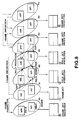
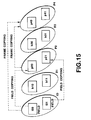
- Figure 7 illustrates the timing of the skip picture flag SPC when a duplicate field is detected.
- fields 0 through 9 of the video signal VI1 which has a field rate of 60 Hz, are derived from frames A through D of a motion picture film source, as described above with reference to Figure 5.
- the fields of the video signal VI1 are then formed into frames as follows: the frame F0 is made up of fields 0 and 1, the frame F1 is made up of fields 2 and 3, the frame F2 is made up of fields 4 and 5, the frame F3 is made up of fields 6 and 7, and the frame F4 is made up of fields 8 and 9.
- the redundancy detection circuit 402 generates the skip picture flag SPC for field 4, a duplicate field indicated by the duplicate detection signal DDS, and for field 7, a duplicate field that duplicates field 9, and which is detected by the redundancy detection circuit 402.
- the skip picture flag for field 4 is generated in response to the duplication detection signal DDS.
- the processing mode selection circuit 103 also generates the skip picture flag SPC when it receives the overflow flag OVF from the encoder 106.
- the overflow flag will be described further below.
- the redundancy detection circuit 402 also generates the skip picture flag SPC if a picture is designated as a skip picture by the duplicate detection signal DDS.
- the encoder 106 includes the skip picture flag SPC and the reference picture code RFC in the coding apparatus output signal VC1 in lieu of each duplicate picture, as will be described below.
- the processing unit decision circuit 403 generates the processing unit flag PUC in response to the delayed video signal VS1 from the delay circuit 401, and in response to the skip picture code SPC from the redundancy detection circuit 402.
- the processing unit flag PUC indicates that frames F2 and F3 are to be coded in field mode since each field in the frames F2 and F3 is derived from a different film source frame.
- the processing unit flag PUC indicates that the other frames F0, F1, and F4 are to be coded in frame mode.
- the prediction mode decision circuit 404 generates the prediction mode code PMC indicating the prediction mode of each picture, and, in response to the skip picture flag, generates the reference picture signal RFC indicating the picture that will be used as the reference picture for reproducing the skip picture.
- the frame B2 made up of fields b20 and b21, and the frame B3, made up of fields b30 and b31, each include fields derived from different film source frames, as described above. Therefore, the prediction mode decision circuit 404 sets the prediction mode code PMC so that these frames will not be used as reference pictures for prediction.
- the prediction mode PMC is set to indicate that the frame is predicted as a P-picture with the earlier fields i10 arid i11 as the reference picture.
- the fields b20 and b31 are designated as skip pictures, and are not separately coded.
- the prediction mode code for the fields b21 and b30 may be set to indicate that the fields will be predicted as B-pictures from the frame of earlier fields i10 and i11 and/or the frame of later fields p40 and p41 by one of three possible prediction modes, as will be described next.
- the prediction mode code PMC indicating the prediction mode used for coding each picture in the present embodiment, will now be described.
- the prediction mode code PMC has three possible states to denote the three possible prediction modes for coding each picture: No prediction.
- the picture is coded by itself, without reference to other pictures (I-picture).
- Forward prediction from an earlier reference picture P-picture.
- Bidirectional prediction which can be from an earlier reference picture, a later reference picture, or by linear interpolation between an earlier reference picture and a later reference picture (B-picture).
- the possible motion prediction modes for each macroblock of a B-picture are as follows: (i) backward prediction from a later picture; (ii) linear prediction from both later and earlier pictures, in which a reference macroblock from the later picture, and a reference macroblock from the earlier picture are processed with linear processing from pixel to pixel, such as by a mean value calculation, to provide a reference macroblock from which the macroblock of the current picture is predicted; and (iii) forward prediction from in earlier picture.
- the reference picture code RFC indicates the picture that is to be used as the reference picture for reproducing the skip picture.
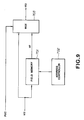
- the scan converting circuit 104 is made up of a field memory 701 which stores the video signal VI2 from the processing mode selection circuit, the address controller 702, and the multiplexer 703, as shown in Figure 9.
- the address controller 702 stores a number of addresses equal to the number of lines in a field and causes the video signal to be read out of the field memory 701 in a specified order to generate the frame-based video signal VF.
- the multiplexer 703 feeds out as the video signal VI3 the field-based video signal VI2 when the processing unit flag PUC indicates field mode coding, and the frame-based video signal VF when the processing unit flag PUC indicates frame mode coding.
- each field is made up of four lines. In this instance, conversion from two fields to one frame is carried out as shown in Figures 9 through 11.
- lines 0 through 3 of field 0 are sequentially written in the line memories A through D of the field memory 701.
- line 0 is then fed to the output from line memory A, and line 4 of field 1 is immediately written into line memory A.
- This operation may be easily realised using the read modified write mode of a DRAM.
- Line 4 is then fed to the output from line memory A, and line 5 of field 1 is immediately written into line memory A.
- Line 1 is fed to the output from line memory B, and line 6 of field 1 is immediately written into line memory B.
- line 5 is fed to the output from line memory A, and line 7 of field 1 is immediately written into line memory A.
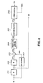
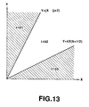
- the operation of the encoder 106 will be described with reference to Figures 8, 12, and 13.
- the arrangement of the encoder 106 is shown in the block diagram of Figure 12, in which the encoder input signal VI4 is supplied to the block-forming circuit 1001.
- the block-forming circuit 1001 derives macroblocks from the encoder input signal VI4 and feeds them to the motion detection circuit 1002, whence they are fed to the subtractor 1003.
- Each macroblock is preferably a square matrix of 16 ⁇ 16 pixel values.
- the subtractor 1003 is also supplied with motion-compensated macroblocks derived from one or more reference pictures by the field memories with motion compensation formed by the predictor 1015 and the field memories 1011 through 1014.
- the subtractor determines the motion prediction error between each pixel in the macroblock of the current picture and the corresponding pixel in the motion-compensated macroblock and feeds the resulting macroblock of motion prediction errors to the DCT circuit 1004.
- the DCT circuit 1004 orthogonally transforms the motion prediction errors from the subtractor 1003 in blocks obtained by dividing each macroblock by four.
- the DCT circuit preferably applies a discrete cosine transform (DCT) to each block.
- the DCT coefficients produced by the DCT circuit 1004 are fed into to the quantizer 1005 where they are quantized using an adaptively-allocated number of bits.
- the quantized DCT coefficients from the quantizer 1005 are fed to the variable-length coding circuit 1006 where they are coded using variable-length coding such as Hufmann coding, or run-length coding.
- the resulting variable-length coded DCT coefficients are fed to the encoder buffer 1007, which provides the encoder output signal VC1, which normally has a constant bit rate.
- the quantized DCT coefficients are also fed from the quantizer 1005 to the dequantizer 1008, where the quantizing applied by the quantizer 1005 is reversed, and thence to the inverse DCT circuit 1009, which performs an inverse orthogonal transform complementary to that performed by the DCT circuit 1004.
- Each resulting macroblock of reconstituted motion prediction errors is fed to the adder 1010, where it is added to the motion-compensated macroblock derived from one or more reference pictures by the predictor 1015.
- the resulting reconstituted macroblock of the current picture is fed to the selector 1017, whence it is fed to one of the field memories with motion compensation 1011 through 1014.
- the overflow flag OVF for preventing an overflow or underflow of the encoder buffer 1007 is fed back from the encoder buffer 1007 to the quantizer 1005, and is also fed to the processing mode selection circuit 103 for use in determining skip pictures, as described above.
- Each macroblock of the current picture is fed from the block-forming circuit 1001 to the motion detection circuit 1002.
- the motion detection circuit 1002 calculates the motion vector between each macroblock of the current picture and at least one possible reference macroblock.
- the motion detection circuit also generates the difference absolute value sum between the macroblock of the current picture and each possible reference macroblock.
- the motion detection circuit feeds the motion vector and the difference absolute value sum for each possible reference macroblock to the motion prediction mode decision circuit 1018.
- the motion detection circuit 1002 calculates the difference absolute value sum X of the motion prediction errors of the macroblock relative to the corresponding macroblock in the later frame, and calculates the difference absolute value sum Y of the motion prediction errors of the macroblock relative to the corresponding macroblock in the earlier frame. Then, the motion prediction mode decision circuit 1018 selects the motion prediction mode as follows: backward prediction from the later frame when Y > jX.
- the predictor 1015 of the field memory set with motion compensation receives the motion prediction mode PM and motion vector MV from the motion prediction mode decision circuit 1018.
- the field memories 1011 through 1014 receive readout addresses from the readout address generating circuit 1016, which generates readout addresses in response to the motion prediction mode PM and the motion vector MV.
- the field memories 1011 through 1014 with motion compensation and the predictor 1015 perform motion compensation in response to the motion prediction mode PM for motion prediction and the motion vector MV.
- the decoding apparatus 101 of the present invention will now be described in more detail.
- the decoder 113 will first be described with reference to Figure 14.
- the decoder input signal VD3, which normally has a constant bit rate, is temporarily stored in the buffer 1201.
- the signal for each picture in the decoder input signal is withdrawn from the buffer 1201, and is fed to the variable-length decoder 1202.
- the variable length decoder reverses the variable length coding applied by the variable length coder 1006 in the encoder, and extracts various control signals and flags.
- the dequantizer 1203 dequantizes each block of the picture signal in accordance with the extracted control signals and flags.
- the inverse DCT circuit 1204 applies an inverse orthogonal transform to each dequantized block, and four blocks of resulting motion prediction errors are combined to provide one macroblock.
- the dequantizer 1203 and the inverse DCT circuit 1204 are constructed to have characteristics that are complementary to those of the quantizer 1005 and the DCT circuit 1004, respectively, in the encoder.
- Each macroblock of motion prediction errors is fed from the inverse DCT circuit 1204 to the adder 1205, where it is added to a corresponding reference macroblock from the predictor 1211.
- the resulting macroblock of the reconstituted current picture is fed to the selector 1206, and also to the field memories 1207 through 1210 of the field memory set with motion compensation.
- Outputs from the field memories 1207 through 1210 are fed via the predictor 1211 to the adder 1205.
- the predictor 1211 generates motion-compensated macroblocks from one or more reference pictures stored in the field memories 1207 through 1210 for combining in the adder 1205 with the macroblocks of motion predication errors generated by the inverse DCT circuit 1204.
- Display addresses from the display address generator 1213 are also supplied to the field memories 1207 through 1210.
- the display address generator 1213 is supplied with frame sync pulse signals from the clock signal generator 1212 which generates clock signals in response to an external clock signal.
- variable-length decoder 1202 also extracts the reference picture code RFD and the skip picture flag SPD which, when it indicates a skip picture, causes the selector 1206 to provide the picture indicated by the reference picture code as a picture of the decoder output signal VO1.
- the frame P4 is a skip picture, its reference frame being the frame P2, the frame P4 is reproduced by copying the frame P2. If the reference frame for the frame P4 is the frame 10, the frame P4 is reproduced by copying the frame I0.
- the frame B1 a B-picture, is processed in field mode with the field b10 as the first field and with the field b11 as the second field.
- the field b10 is a skip picture, and the prediction mode is backward prediction from a later field with the field i00 as the reference picture.
- the field b10 is reproduced by coping the field i00.
- the prediction mode of the field b10 is forward prediction from an earlier field, with the reference picture being, e.g., the field p21, the field b10 is reproduced by copying the field p21.
- the field b10 is reproduced by linear prediction from the field i00 and the field p21.
- a reference macroblock from the later field and a reference macroblock from the earlier field are linearly processed pixel by pixel, such as by a mean value calculation, to provide a macroblock of the field b10.
- B-pictures may be processed in frame mode. If the frame B3, a B-picture, is processed in frame mode, and the prediction mode is backward prediction from a later picture, with the reference picture being, e.g., the frame I0, the frame B3 is reproduced by copying the frame I0.
- the frame B3 may be reproduced by copying the frame P4.
- the frame B3 is reproduced by linear prediction from frames I0 and P4.
- a reference macroblock from the later frame and a reference macroblock from the earlier frame are linearly processed pixel by pixel, such as by a mean value calculation, to provide a macroblock of the frame B3.
- the coding apparatus 840 according to the second embodiment will be described first.
- the coder input signal VI a video signal with a field rate of 60 Hz
- the 2-3 pulldown detection circuit 832 which detects duplicate fields and generates the duplication detection signal DDS in response to each duplicate field.
- the 2-3 pulldown detection circuit feeds out the coder input signal VI delayed by a delay time equal to the processing time of the 2-3 pulldown detection circuit as the video signal VI1.
- the processing mode selection circuit 833 generates from the video signal VI1 and the duplication detection signal DDS the following four signals for each picture represented by the video signal VI1, in the same manner as described above: the skip picture flag SPC, which indicates whether the picture is a duplicate picture, i.e., a picture that has little or no change relative to another picture; the processing unit flag PUC, which indicates whether the picture is to be coded using frame mode coding or field mode coding; the prediction mode code PMC, which indicates the prediction mode for the picture.
- the skip picture flag SPC which indicates whether the picture is a duplicate picture, i.e., a picture that has little or no change relative to another picture
- the processing unit flag PUC which indicates whether the picture is to be coded using frame mode coding or field mode coding
- the prediction mode code PMC which indicates the prediction mode for the picture.
- the prediction mode code indicates whether the picture is to be coded as an I-picture (no prediction), a P-picture (forward predictive coding) or a B-picture (backward, bidirectional, or forward predictive coding); and the reference picture code RFC, which indicates, when the picture is a skip picture, the picture that is to be used as the reference picture for reproducing the skip picture.
- the processing mode selection circuit also delays the video signal VI1 by the processing time of the processing mode selecting circuit 103 before feeding it out as the video signal VI2.
- the field sequence changing and scan converting circuit 834 converts two fields of the field-based video signal VI2 into one frame.
- the processing unit flag PUC indicates that the picture will be coded in field mode
- the field sequence changing and scan converting circuit 834 does not perform a field-to-frame conversion.
- the field sequence exchange and scan converting circuit 834 changes the picture (field or frame) sequence of the video signal VI2 to the sequence required by the encoder 836.
- the picture sequence is changed in response to the skip picture flag SPC, the processing unit flag PUC, the prediction mode code PMC, and the reference picture code RFC to provide the encoder input signal VI4.
- the encoder 836 encodes the video signal VI4 in response to the skip picture flag SPC, the processing unit flag PUC, the prediction mode code PMC and the reference picture code RFC generated by the processing mode selecting circuit 833.
- the encoder provides the resulting coded signal as the encoder output signal VC1.
- the encoder also includes the skip picture flag SPC, the processing unit flag PUC, the prediction mode code PMC and the reference picture code RFC from the processing mode selecting circuit 833, and the temporal-reference in the encoder output signal VC1.
- the error correction coding (ECC) circuit 837 appends error correction codes to the encoded signal VC1 to provide the encoded signal VC2, which is modulated by the modulator 838 to provide the recording signal VC3 for recording on the recording medium 839.
- ECC error correction coding
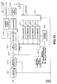
- the decoding apparatus 850 will now be described, also with reference to Figure 17.
- the recorded signal VD1 read out from the recording medium 840, is demodulated by the demodulating circuit 841 to provide the demodulated signal VD2.
- the recording medium 840 is the same as, or is derived from, the recording medium 839.
- the ECC decoding circuit 842 detects and corrects errors in the demodulated signal VD2 to provide the decoder input signal VD3.
- the decoder input signal VD3 is fed into the decoder 843, which extracts from the decoder input signal VD3 the skip picture flag SPC, the processing unit flag PUC, the prediction mode code PMC, the reference picture code RFC, and the temporal_reference for each picture. These flags and codes were originally generated by the processing mode selecting circuit 833 and the temporal reference generator 1020 in the coding apparatus 840.
- the decoder provides these flags and codes as the skip picture flag SPD, the processing unit flag PUD, the prediction mode code PMD, the reference picture code RFD, and the temporal_reference.
- the decoder 843 also decodes the picture signal in the decoder input signal VD3 to provide the decoding apparatus output signal VO.
- the field sequence exchanging and scan converting circuit 844 of the decoding apparatus 850 of the second embodiment causes the decoder 843 to convert those pictures indicated by the processing unit flag PUD decoded by the decoder 843 as having been coded in frame mode into two fields of the decoding apparatus output signal VO. Otherwise, the circuit 844 causes the decoder to provide each two fields decoded from the decoder input signal VD3 as two fields of decoding apparatus output signal VO without conversion.
- the field sequence exchange and scan converting circuit 844 also causes the decoder 843 to change the picture sequence of the decoder input signal VD3 so that the picture sequence of the decoding apparatus output signal VO is the same as that of the coder input signal VI.
- the field sequence exchange and scan converting circuit 844 causes the decoder 843 to change the picture sequence in response to the skip picture flag SPD, the processing unit flag PUD, the prediction mode code PMD, and the reference picture code RFD, and the temporal_reference decoded by decoder 843.
- the resulting decoding apparatus output signal VO is a video signal that is suitable for display on a monitor after conversion to an analog signal.
- the coding apparatus 840 will now be described in more detail.
- the construction and operation of the 2-3 pulldown detection circuit 832 are similar to those described above with reference to Figures 4 and 5, and so will not be described again here.
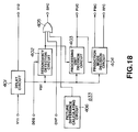
- processing mode selection circuit 833 according to the second embodiment of the invention is shown in Figure 18. Operation of the circuit is similar to that described above with reference to Figures 7 and 8.
- the video signal VI1 is supplied to the delay circuit 401, which delays the video signal VI1 by different multiples of a field period and feeds multiple delayed signals out as the video signal VS1.
- the delay circuit 401 also delays the video signal VI1 by a delay equal to the processing time of the processing mode selection circuit 103, and feeds the delayed video signal to the scan converter and field sequence exchange circuit 834 as the video signal VI2.
- the redundancy detection circuit 402 detects duplicate pictures (field or frame) in the video signal VI1.
- a duplicate picture is a picture that exhibits little or no change relative to another picture.
- the redundancy detection circuit 402 generates the skip picture flag SPC in response to each duplicate picture indicated by the duplication detection signal DDS.
- the picture difference calculating circuit 406 calculates the pixel-by-pixel difference between the current picture and plural other pictures in the video signal VS1. If the sum of the differences between the current picture and one of the other pictures is not greater than a certain threshold value, it is deemed that the picture exhibits little or no change relative to that other picture, and the picture difference calculating circuit 406 generates a skip picture flag SPC. In addition, the prediction mode decision circuit 404 generates a reference picture code RFC indicating the other picture as the reference picture for reproducing the skip picture.
- the threshold value may be increased when it is desired to increase the number of duplicate pictures skipped, and may be reduced when it is desired to increase the picture quality.
- the processing mode selection circuit 833 also generates the skip picture flag SPC when it receives the overflow flag OVF from the encoder 836.
- the processing mode selection circuit 833 includes the three-input OR gate 405, which ORs the outputs of the redundancy detection circuit 402, the picture difference calculating circuit 406, and the overflow flag OVF to provide the skip picture flag SPC.
- the processing mode selection circuit 833 also generates the skip picture flag SPC when the picture is intentionally designated as a skip picture, by, for example, the duplicate detection signal DDS.
- the encoder 836 includes the reference picture code RFC and the skip picture flag SPC together in the coding apparatus output signal VC1 in lieu of each skip picture, as will be described in detail below.
- the prediction mode decision circuit 404 generates the prediction mode code PMC for each picture and the reference picture code RFC in response to each skip picture flag SPC.
- the prediction mode is the same as that described above with reference to Figure 8.
- the prediction mode code PMC has three possible states to denote the three possible motion prediction modes that can be used to code each picture: No prediction.
- the picture is coded by itself without reference to another picture (I picture); Forward prediction made from an earlier reference picture (P-picture); and Bidirectional prediction from an earlier reference picture, a later reference picture, or by linear interpolation between an earlier reference picture and a later reference picture (B-picture).
- the possible motion prediction modes for each macroblock of a B-picture are as follows; (i) backward prediction from a later picture; (ii) linear prediction from both later and earlier pictures, in which a reference macroblock from the later picture and a reference macroblock from the earlier picture are processed with linear processing from pixel to pixel, such as by mean value calculation, to provide a reference macroblock from which the macroblock of the current picture is predicted; and (iii) forward prediction from an earlier picture.
- the construction of the field sequence exchanging and scan converting circuit 834 is shown in Figure 19.
- the operation of the field sequence exchanging and scan converting circuit 834 is similar to that described above with reference to Figures 9 through 11.
- the field sequence exchanging and scan converting circuit 834 is made lip of the field memory set 241 for storing fields of the video signal VI2, and the address controller 242.
- the address controller 242 provides field-to-frame conversion by generating addresses for reading out alternate lines of the encoder input signal VI4 from the field memory set 241 in a manner similar to that described above with reference to Figure 10 and 11.
- the address controller 242 In response to the processing mode flag PMC, the processing mode code PUC and the skip picture flag SPC, the address controller 242 generates addresses for reading pictures out of the field memory set 241 so that the pictures in the encoder input signal VI4 are arranged in the processing order required by the encoder 863.
- the address controller 242 also generates the addresses for reading out from the field memory set 241 in response to the skip picture flag SPC, the processing unit flag PUC, and the prediction mode code PMC received from the processing mode selection circuit 803.
- the construction of the encoder 863, shown in Figure 20, is substantially similar to that described above with reference to Figure 12.
- the encoder 863 additionally includes the temporal reference generating circuit 1020, which generates, in response to the prediction mode code PMC, a temporal_reference code for each picture.
- the temporal_reference code is a 10-bit code that indicates the display sequence of the picture in a group of pictures (GOP).
- the temporal_reference code is generated by incrementing a counter by one for each consecutive picture in the coder input signal VI. The counter is reset to zero at the beginning of each GOP, or when the number of pictures in the GOP exceeds 1024.
- the temporal reference generator feeds the temporal_reference code to the variable-length coder 1006 for inclusion in the coding apparatus output signal VC1.
- Figure 20 also shows that the skip picture flag SPC, the processing unit flag PUC, the prediction mode code PMC, the reference picture code RFC, the motion prediction mode PM, and the motion vector MV are fed to the variable-length coder 1006 for inclusion in the coder output signal VC1. and that the skip picture flag SPC, the processing unit flag PUC, and the prediction mode code PMC are supplied to the motion prediction mode decision circuit 1018.
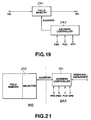
- decoder 843 The construction of the decoder 843 is similar to that shown in Figure 14. However, the relation between the decoder 843 and the field sequence exchanging and scan converting circuit 844 in the second embodiment of the decoding apparatus 850, shown in Figures 17 and 21, is different from that shown in Figure 3.
- the field sequence exchanging and scan converting circuit 844 executes scan conversion and field sequence exchange in response to the skip picture flag SPD, the processing unit flag PUD, the prediction mode code PMD, the reference picture code RFD, and the temporal_reference extracted from the decoder input signal by the decoder 843.
- the field sequence exchanging and scan converting circuit 844 consists of the address controller 251, which receives the skip picture flag SPD, the processing unit flag PUD, the prediction mode code PMD, the reference picture code RFD, and the temporal_reference code extracted from the decoder input signal.
- the field sequence exchanging and scan converting circuit 844 feeds readout addresses to the field memory set 252 with selector in the decoder 843 to cause the field memory set 252 to read out the field of the decoding apparatus output signal VO indicated by each readout address.
- the field memory set 252 is provided by the field memories 1207 through 1210 and the selector 1206 shown in Figure 14.
- the coding apparatus 840 shown in Figure 22 employs the 2-3 pulldown detection circuit 832, the processing mode selection circuit 833, the scan converter and field sequence exchange circuit 860, the first encoder 861 and the second encoder 863, and the duplicate picture detection circuit 862.
- the 2-3 pulldown detection circuit 832, the scan converter and field sequence exchange circuit 834, and the second encoder 863 shown in Figure 22 are similar to the 2-3 pulldown detection circuit 832, the scan converter and field sequence exchange circuit 834, and the encoder 836, respectively, shown in Figure 17.
- the processing mode selection circuit 860 is similar to the processing mode selection circuit 833 shown in Figures 17 and 18, but lacks the redundancy detection circuit 402, the picture difference calculating circuit 406, and the OR gate 405 shown in Figure 18. Moreover, the prediction mode decision circuit 404 does not generate a reference picture code RFC. Thus, the processing mode selection circuit 860 simply generates the processing unit flag PUC, and the prediction mode code PMC.
- the video signal VI2, the processing unit flag PUC, and the prediction mode code PMC are fed into the scan converter and field sequence exchange circuit 834, which, in response to the processing unit flag PUC, selectively interleaves the fields of the video signal VI2 to provide a progressive picture.
- the scan converter and field sequence exchange circuit 834 additionally rearranges the order of the pictures in the video signal VI2 to that required by the encoders 861 and 863 in response to the prediction mode code PMC, as described above.
- the scan converter and field sequence exchange circuit 834 provides the encoder input signal VI4.
- the first encoder 861 codes the encoder input signal VI4 in a conventional manner. Since the first encoder 861 receives no skip picture flag SPC, or other duplicate picture information, the first encoder codes all pictures in the encoder input signal VI4, including duplicate pictures.
- the resulting coded output signal VC2 is fed from the first encoder 861 to the duplicate picture detection circuit 862, which checks whether the coding of any of the pictures in the coded output signal VC2 meets the conditions that indicate that the picture is a duplicate picture, and need not be coded.
- a coded picture is determined to be a duplicate picture if it meets the following conditions: If the picture is coded as a P-picture:
- the duplicate picture detection circuit 862 generates a skip picture flag SPC and a reference picture code RFC for each picture (frame or field) that it finds which satisfies the above-mentioned conditions.
- the reference picture code RFC indicates the picture that is to be used as the reference picture to duplicate the skip picture.
- the duplicate picture detection circuit 862 additionally receives the duplicate detection signal DDS from the 2-3 pulldown detection circuit 832, and additionally generates a skip picture flag SPC and a reference picture code RFC for each picture that the duplicate detection signal DDS indicates is a duplicate picture.
- the duplicate picture detection circuit 862 feeds each skip picture flag SPC and each reference picture code RFC to the second encoder 863.
- the second encoder 863 which is identical to the encoder 836 shown in Figure 17, also receives the input signal VI4; the processing unit flag PUC and the prediction mode code PMC from the processing mode decision circuit 860; and the skip picture flag SPC and the reference picture code RFC from the duplicate picture detection circuit 862. In response to these control signals and flags, the second encoder 863 encodes the encoder input signal VI4 in the same way as the encoder 836 described above with reference to Figure 17. When the skip picture flag SPC indicates that a picture is a duplicate picture, the second encoder 863 inserts the skip picture flag and the reference picture code RFC into the coding apparatus output signal VC1 in lieu of the duplicate picture.
- the decoder for a signal coded by the coding apparatus shown in Figure 22 is identical to the decoder 101 shown in Figure 17, and so will not be described again here.
- the recording medium 109 or 110 shown in Figure 3, or the recording medium 839 or 840 shown in Figure 17, is a recording medium on which are recorded signals coded by the above-mentioned coding apparatus of the present invention.
- the skip picture flag SPC, the processing unit flag PUC, the prediction mode code PMC, the reference picture code RFC, motion vector MV, the motion prediction mode PM, and the temporal_reference are included together with the signal for each picture in the recording signal recorded on the recording medium to indicate the coding parameters of each picture.
- the recording medium may be a disc-shaped recording medium, such as an optical disc, recordable optical disc, or a hard disc, a tape-based recording medium, a semiconductor memory, or an IC card.
- the coding apparatus output signal VC1 may be broadcast using a suitable broadcast system, cable distribution system, telephone system, etc.
- the unit in which each picture is coded may be adaptively switched between fields and frames, in response to the properties of input picture signal, the coding efficiency may be increased compared with processing the picture signal solely in units of fields or units of frames.
- coding a frame derived from two consecutive frames of a motion picture film source on a field-by-field basis further improves the compression efficiency.
- a frame derived from two consecutive frames of a motion picture film source is coded such that it is not used as a reference frame for predicting other pictures. The prevents the reduced quality of this frame from lowering the picture quality of other frames.
- the compression efficiency is further increased by not coding each duplicate picture, and by including a skip picture flag in the coding apparatus output signal instead.
- Recording a video signal coded as just described on the recording medium uses the recording capacity of the recording medium more effectively.
- a decoding apparatus designed for executing the decoding method will produce decoded pictures with a high picture quality.
Priority Applications (3)
| Application Number | Priority Date | Filing Date | Title |
|---|---|---|---|
| EP19980120885 EP0893917A3 (fr) | 1992-09-18 | 1993-09-20 | Codage et décodage de signaux vidéo numériques ayant des images répétées avec des trames provenant de différentes images issues de films |
| EP19980120886 EP0893918B1 (fr) | 1992-09-18 | 1993-09-20 | Codage et décodage de signaux vidéo numériques ayant des images répétées avec des trames provenant de différentes images issues de films |
| EP19980120887 EP0897241B1 (fr) | 1992-09-18 | 1993-09-20 | Codage et décodage de signaux vidéo numériques ayant des images répétées avec des trames provenant de différentes images issues de films |
Applications Claiming Priority (9)
| Application Number | Priority Date | Filing Date | Title |
|---|---|---|---|
| JP24979292 | 1992-09-18 | ||
| JP249792/92 | 1992-09-18 | ||
| JP24979292 | 1992-09-18 | ||
| JP29169692 | 1992-10-29 | ||
| JP291696/92 | 1992-10-29 | ||
| JP29169692 | 1992-10-29 | ||
| JP16674593A JP3443880B2 (ja) | 1992-09-18 | 1993-07-06 | ビデオ信号符号化方法及び復号化方法 |
| JP166745/93 | 1993-07-06 | ||
| JP16674593 | 1993-07-06 |
Related Child Applications (3)
| Application Number | Title | Priority Date | Filing Date |
|---|---|---|---|
| EP19980120886 Division EP0893918B1 (fr) | 1992-09-18 | 1993-09-20 | Codage et décodage de signaux vidéo numériques ayant des images répétées avec des trames provenant de différentes images issues de films |
| EP19980120887 Division EP0897241B1 (fr) | 1992-09-18 | 1993-09-20 | Codage et décodage de signaux vidéo numériques ayant des images répétées avec des trames provenant de différentes images issues de films |
| EP19980120885 Division EP0893917A3 (fr) | 1992-09-18 | 1993-09-20 | Codage et décodage de signaux vidéo numériques ayant des images répétées avec des trames provenant de différentes images issues de films |
Publications (3)
| Publication Number | Publication Date |
|---|---|
| EP0588668A2 true EP0588668A2 (fr) | 1994-03-23 |
| EP0588668A3 EP0588668A3 (fr) | 1994-11-23 |
| EP0588668B1 EP0588668B1 (fr) | 1999-06-09 |
Family
ID=27322741
Family Applications (4)
| Application Number | Title | Priority Date | Filing Date |
|---|---|---|---|
| EP19930307404 Expired - Lifetime EP0588668B1 (fr) | 1992-09-18 | 1993-09-20 | Codage et décodage de signaux vidéo digitaux ayant des images repetées avec des trames provenant de differents champs issus de films |
| EP19980120885 Withdrawn EP0893917A3 (fr) | 1992-09-18 | 1993-09-20 | Codage et décodage de signaux vidéo numériques ayant des images répétées avec des trames provenant de différentes images issues de films |
| EP19980120887 Expired - Lifetime EP0897241B1 (fr) | 1992-09-18 | 1993-09-20 | Codage et décodage de signaux vidéo numériques ayant des images répétées avec des trames provenant de différentes images issues de films |
| EP19980120886 Expired - Lifetime EP0893918B1 (fr) | 1992-09-18 | 1993-09-20 | Codage et décodage de signaux vidéo numériques ayant des images répétées avec des trames provenant de différentes images issues de films |
Family Applications After (3)
| Application Number | Title | Priority Date | Filing Date |
|---|---|---|---|
| EP19980120885 Withdrawn EP0893917A3 (fr) | 1992-09-18 | 1993-09-20 | Codage et décodage de signaux vidéo numériques ayant des images répétées avec des trames provenant de différentes images issues de films |
| EP19980120887 Expired - Lifetime EP0897241B1 (fr) | 1992-09-18 | 1993-09-20 | Codage et décodage de signaux vidéo numériques ayant des images répétées avec des trames provenant de différentes images issues de films |
| EP19980120886 Expired - Lifetime EP0893918B1 (fr) | 1992-09-18 | 1993-09-20 | Codage et décodage de signaux vidéo numériques ayant des images répétées avec des trames provenant de différentes images issues de films |
Country Status (5)
| Country | Link |
|---|---|
| US (2) | US5835672A (fr) |
| EP (4) | EP0588668B1 (fr) |
| JP (1) | JP3443880B2 (fr) |
| KR (1) | KR100271543B1 (fr) |
| DE (3) | DE69331399T2 (fr) |
Cited By (12)
| Publication number | Priority date | Publication date | Assignee | Title |
|---|---|---|---|---|
| EP0639032A2 (fr) * | 1993-08-09 | 1995-02-15 | C-Cube Microsystems, Inc. | Structure et méthode pour un vidéo codeur/décodeur multistandard |
| EP0661885A1 (fr) * | 1993-12-28 | 1995-07-05 | Canon Kabushiki Kaisha | Méthode de traitement d'images et appareil pour la conversion de données codés selon différents formats |
| EP0720371A2 (fr) * | 1994-12-29 | 1996-07-03 | Sony Corporation | Méthode de traitement de signaux d'images animées numériques |
| EP0730378A2 (fr) * | 1995-02-28 | 1996-09-04 | Sony Corporation | Codage et décodage de signaux d'image |
| EP0720366A3 (fr) * | 1994-12-30 | 1996-12-27 | Thomson Consumer Electronics | Méthode et appareil pour l'identification de trames vidéo produites par des sources de films utilisant des séquences d'entraînements intermittents 2-2 et 3-2 |
| EP0708564A3 (fr) * | 1994-10-21 | 1997-11-19 | AT&T Corp. | Procédé de contrÔle de codage |
| US5910909A (en) * | 1995-08-28 | 1999-06-08 | C-Cube Microsystems, Inc. | Non-linear digital filters for interlaced video signals and method thereof |
| WO1999063747A2 (fr) * | 1998-06-04 | 1999-12-09 | Koninklijke Philips Electronics N.V. | Systeme de detection d'images redondantes dans une sequence video |
| WO2001013647A1 (fr) * | 1999-08-17 | 2001-02-22 | Tiernan Communications, Inc. | Procede et appareil pour detection en telecinema |
| WO2001065857A1 (fr) * | 2000-02-29 | 2001-09-07 | Koninklijke Philips Electronics N.V. | Detection et codage de video de source film |
| WO2006038716A1 (fr) | 2004-10-07 | 2006-04-13 | Matsushita Electric Industrial Co., Ltd. | Appareil de codage d'images et appareil de decodage d'images |
| EP2109320A3 (fr) * | 2008-04-11 | 2011-01-05 | Sony Corporation | Appareil et procédé de traitement d'informations |
Families Citing this family (26)
| Publication number | Priority date | Publication date | Assignee | Title |
|---|---|---|---|---|
| WO1997027704A1 (fr) | 1993-04-21 | 1997-07-31 | Kinya Washino | Systeme de production audio/video multiformat avec conversion de la frequence de trames |
| US6058140A (en) * | 1995-09-08 | 2000-05-02 | Zapex Technologies, Inc. | Method and apparatus for inverse 3:2 pulldown detection using motion estimation information |
| US6441813B1 (en) | 1997-05-16 | 2002-08-27 | Kabushiki Kaisha Toshiba | Computer system, and video decoder used in the system |
| US6151075A (en) * | 1997-06-11 | 2000-11-21 | Lg Electronics Inc. | Device and method for converting frame rate |
| DE69836470T2 (de) * | 1997-07-15 | 2007-03-15 | Matsushita Electric Industrial Co., Ltd., Kadoma | Überträger, empfänger und medium für progressives bildsignal |
| JP3523026B2 (ja) * | 1997-09-04 | 2004-04-26 | 三菱電機株式会社 | 画像信号処理装置 |
| US6154257A (en) * | 1998-03-06 | 2000-11-28 | Pioneer Electronic Corporation | Method for identifying input video signal and processing the video signal |
| US6066980A (en) * | 1998-04-07 | 2000-05-23 | Lsi Logic Corporation | Near Nyquist rate variable rate receiver |
| US6670996B2 (en) * | 1998-08-20 | 2003-12-30 | Intel Corporation | Apparatus and method for display of progressive and interland video content |
| US6400895B1 (en) * | 1999-01-26 | 2002-06-04 | Ati International Srl | Method for optimizing MPEG-2 video playback consistency |
| JP3847024B2 (ja) * | 1999-05-25 | 2006-11-15 | パイオニア株式会社 | 映像信号変換装置 |
| US6636648B2 (en) * | 1999-07-02 | 2003-10-21 | Eastman Kodak Company | Albuming method with automatic page layout |
| FR2804274B1 (fr) * | 2000-01-25 | 2002-04-12 | St Microelectronics Sa | Decodeur mpeg d'images de sequences multiples |
| JP2002185849A (ja) * | 2000-12-18 | 2002-06-28 | Nec Corp | 出力装置、及びテレシネ表示方法 |
| US7174086B2 (en) * | 2001-10-23 | 2007-02-06 | Thomson Licensing | Trick mode using dummy predictive pictures |
| US20030099294A1 (en) * | 2001-11-27 | 2003-05-29 | Limin Wang | Picture level adaptive frame/field coding for digital video content |
| KR20040054032A (ko) * | 2002-12-16 | 2004-06-25 | 삼성전자주식회사 | 영상신호의 포맷 검출장치 및 방법 |
| KR100510671B1 (ko) * | 2003-01-08 | 2005-08-31 | 엘지전자 주식회사 | 인터레이스 영상에서의 동일 프레임 검출 장치 |
| KR100503090B1 (ko) * | 2003-06-21 | 2005-07-21 | 삼성전자주식회사 | 주파수 변환을 사용한 영화 영상 검출 방법 및 장치 |
| KR100627500B1 (ko) * | 2004-03-10 | 2006-09-21 | 엘지전자 주식회사 | 모바일폰의 단문 메시지 제공시스템 및 그 제공방법 |
| JP4262139B2 (ja) * | 2004-06-01 | 2009-05-13 | キヤノン株式会社 | 信号処理装置 |
| ES2383611T3 (es) * | 2005-08-15 | 2012-06-22 | Nds Limited | Sistema de modo de trucos de vídeo |
| BRPI0809210A2 (pt) * | 2007-04-04 | 2014-09-02 | Thomson Licensing | Gerenciamento de lista de imagens de referência |
| JP4856008B2 (ja) * | 2007-05-29 | 2012-01-18 | シャープ株式会社 | 画像再符号化装置および画像再符号化方法 |
| US20120195366A1 (en) * | 2011-02-01 | 2012-08-02 | Mediatek Singapore Pte. Ltd. | Method and Apparatus of Adaptive Inter Mode Coding Using Variable Length Codes |
| RU2510589C2 (ru) * | 2012-07-05 | 2014-03-27 | Вадим Витальевич Ярошенко | Способ кодирования цифрового видеоизображения |
Citations (4)
| Publication number | Priority date | Publication date | Assignee | Title |
|---|---|---|---|---|
| US4788589A (en) * | 1985-11-30 | 1988-11-29 | Sony Corporation | Method and apparatus for transmitting video data |
| WO1991006182A1 (fr) * | 1989-10-20 | 1991-05-02 | Snell & Wilcox Limited | Conversion des normes de television numeriques |
| GB2240232A (en) * | 1990-01-17 | 1991-07-24 | Avesco Plc | Converting field rate of telecine signal |
| WO1991013520A1 (fr) * | 1990-02-23 | 1991-09-05 | Massachusetts Institute Of Technology | Procede et appareil de reduction/reconstruction d'images video |
Family Cites Families (15)
| Publication number | Priority date | Publication date | Assignee | Title |
|---|---|---|---|---|
| JP2797404B2 (ja) * | 1989-04-20 | 1998-09-17 | ソニー株式会社 | 動画像データの記録方式 |
| GB2231228B (en) * | 1989-04-27 | 1993-09-22 | Sony Corp | Video signal to photographic film conversion |
| US5140637A (en) * | 1989-12-01 | 1992-08-18 | Arnold Kaplan | Device and method for removing vocal signals |
| US5221966A (en) * | 1990-01-17 | 1993-06-22 | Avesco Plc | Video signal production from cinefilm originated material |
| DE69114083T2 (de) * | 1990-08-29 | 1996-04-04 | Sony Uk Ltd | Verfahren und Gerät zum Umsetzung eines Filmes in Videosignale. |
| CA2062200A1 (fr) * | 1991-03-15 | 1992-09-16 | Stephen C. Purcell | Processeur de decompression pour applications video |
| US5267035A (en) * | 1991-08-08 | 1993-11-30 | Samsung Electronics Co., Ltd. | Motion detection for video including that obtained from film |
| JPH05137131A (ja) * | 1991-11-13 | 1993-06-01 | Sony Corp | フレーム間動き予測方法 |
| US5510840A (en) * | 1991-12-27 | 1996-04-23 | Sony Corporation | Methods and devices for encoding and decoding frame signals and recording medium therefor |
| KR950001562B1 (ko) * | 1991-12-28 | 1995-02-25 | 주식회사금성사 | Tv의 화면 종횡비 변환방법 및 장치 |
| US5272529A (en) * | 1992-03-20 | 1993-12-21 | Northwest Starscan Limited Partnership | Adaptive hierarchical subband vector quantization encoder |
| US5241382A (en) * | 1992-04-25 | 1993-08-31 | General Instrument Corporation | Digital HDTV data packet format and receiver therefor |
| US5278647A (en) * | 1992-08-05 | 1994-01-11 | At&T Bell Laboratories | Video decoder using adaptive macroblock leak signals |
| US5461420A (en) * | 1992-09-18 | 1995-10-24 | Sony Corporation | Apparatus for coding and decoding a digital video signal derived from a motion picture film source |
| US5491516A (en) * | 1993-01-14 | 1996-02-13 | Rca Thomson Licensing Corporation | Field elimination apparatus for a video compression/decompression system |
-
1993
- 1993-07-06 JP JP16674593A patent/JP3443880B2/ja not_active Expired - Lifetime
- 1993-09-18 KR KR1019930018927A patent/KR100271543B1/ko not_active IP Right Cessation
- 1993-09-20 US US08/124,299 patent/US5835672A/en not_active Expired - Lifetime
- 1993-09-20 DE DE1993631399 patent/DE69331399T2/de not_active Expired - Lifetime
- 1993-09-20 DE DE1993625220 patent/DE69325220T2/de not_active Expired - Lifetime
- 1993-09-20 EP EP19930307404 patent/EP0588668B1/fr not_active Expired - Lifetime
- 1993-09-20 EP EP19980120885 patent/EP0893917A3/fr not_active Withdrawn
- 1993-09-20 EP EP19980120887 patent/EP0897241B1/fr not_active Expired - Lifetime
- 1993-09-20 DE DE1993631244 patent/DE69331244T2/de not_active Expired - Lifetime
- 1993-09-20 EP EP19980120886 patent/EP0893918B1/fr not_active Expired - Lifetime
-
1996
- 1996-10-29 US US08/740,465 patent/US5768469A/en not_active Expired - Lifetime
Patent Citations (4)
| Publication number | Priority date | Publication date | Assignee | Title |
|---|---|---|---|---|
| US4788589A (en) * | 1985-11-30 | 1988-11-29 | Sony Corporation | Method and apparatus for transmitting video data |
| WO1991006182A1 (fr) * | 1989-10-20 | 1991-05-02 | Snell & Wilcox Limited | Conversion des normes de television numeriques |
| GB2240232A (en) * | 1990-01-17 | 1991-07-24 | Avesco Plc | Converting field rate of telecine signal |
| WO1991013520A1 (fr) * | 1990-02-23 | 1991-09-05 | Massachusetts Institute Of Technology | Procede et appareil de reduction/reconstruction d'images video |
Non-Patent Citations (1)
| Title |
|---|
| IEEE TRANSACTIONS ON BROADCASTING, vol.36, no.4, December 1990, NEW YORK US pages 245 - 254 PAIK 'digicipher-all digital, channel compatible, hdtv broadcast system' * |
Cited By (26)
| Publication number | Priority date | Publication date | Assignee | Title |
|---|---|---|---|---|
| EP0639032A3 (fr) * | 1993-08-09 | 1995-11-29 | C Cube Microsystems | Structure et méthode pour un vidéo codeur/décodeur multistandard. |
| US6071004A (en) * | 1993-08-09 | 2000-06-06 | C-Cube Microsystems, Inc. | Non-linear digital filters for interlaced video signals and method thereof |
| EP0639032A2 (fr) * | 1993-08-09 | 1995-02-15 | C-Cube Microsystems, Inc. | Structure et méthode pour un vidéo codeur/décodeur multistandard |
| US5740340A (en) * | 1993-08-09 | 1998-04-14 | C-Cube Microsystems, Inc. | 2-dimensional memory allowing access both as rows of data words and columns of data words |
| US5598514A (en) * | 1993-08-09 | 1997-01-28 | C-Cube Microsystems | Structure and method for a multistandard video encoder/decoder |
| US5630033A (en) * | 1993-08-09 | 1997-05-13 | C-Cube Microsystems, Inc. | Adaptic threshold filter and method thereof |
| US6122442A (en) * | 1993-08-09 | 2000-09-19 | C-Cube Microsystems, Inc. | Structure and method for motion estimation of a digital image by matching derived scores |
| EP0661885A1 (fr) * | 1993-12-28 | 1995-07-05 | Canon Kabushiki Kaisha | Méthode de traitement d'images et appareil pour la conversion de données codés selon différents formats |
| EP0708564A3 (fr) * | 1994-10-21 | 1997-11-19 | AT&T Corp. | Procédé de contrÔle de codage |
| EP0720371A3 (fr) * | 1994-12-29 | 1997-10-22 | Sony Corp | Méthode de traitement de signaux d'images animées numériques |
| CN1134165C (zh) * | 1994-12-29 | 2004-01-07 | 索尼公司 | 运动图形处理方法和设备以及恢复信号产生方法和设备 |
| KR100392856B1 (ko) * | 1994-12-29 | 2003-10-22 | 소니 가부시끼 가이샤 | 동화상처리방법 |
| EP0720371A2 (fr) * | 1994-12-29 | 1996-07-03 | Sony Corporation | Méthode de traitement de signaux d'images animées numériques |
| EP0720366A3 (fr) * | 1994-12-30 | 1996-12-27 | Thomson Consumer Electronics | Méthode et appareil pour l'identification de trames vidéo produites par des sources de films utilisant des séquences d'entraînements intermittents 2-2 et 3-2 |
| EP0730378A3 (fr) * | 1995-02-28 | 1998-02-11 | Sony Corporation | Codage et décodage de signaux d'image |
| EP0730378A2 (fr) * | 1995-02-28 | 1996-09-04 | Sony Corporation | Codage et décodage de signaux d'image |
| US5982444A (en) * | 1995-02-28 | 1999-11-09 | Sony Corporation | Encoding method and apparatus for encoding edited picture signals, signal recording medium and picture signal decoding method and apparatus |
| US5910909A (en) * | 1995-08-28 | 1999-06-08 | C-Cube Microsystems, Inc. | Non-linear digital filters for interlaced video signals and method thereof |
| WO1999063747A3 (fr) * | 1998-06-04 | 2000-04-06 | Koninkl Philips Electronics Nv | Systeme de detection d'images redondantes dans une sequence video |
| WO1999063747A2 (fr) * | 1998-06-04 | 1999-12-09 | Koninklijke Philips Electronics N.V. | Systeme de detection d'images redondantes dans une sequence video |
| WO2001013647A1 (fr) * | 1999-08-17 | 2001-02-22 | Tiernan Communications, Inc. | Procede et appareil pour detection en telecinema |
| WO2001065857A1 (fr) * | 2000-02-29 | 2001-09-07 | Koninklijke Philips Electronics N.V. | Detection et codage de video de source film |
| US6963377B2 (en) | 2000-02-29 | 2005-11-08 | Koninklijke Philips Electronics N.V. | Encoding method and device including thresholding pixel-to-pixel differences |
| WO2006038716A1 (fr) | 2004-10-07 | 2006-04-13 | Matsushita Electric Industrial Co., Ltd. | Appareil de codage d'images et appareil de decodage d'images |
| US8514938B2 (en) | 2004-10-07 | 2013-08-20 | Hewlett-Packard Development Company L.P. | Picture coding apparatus for a still picture sequence and picture decoding apparatus for a still picture sequence |
| EP2109320A3 (fr) * | 2008-04-11 | 2011-01-05 | Sony Corporation | Appareil et procédé de traitement d'informations |
Also Published As
| Publication number | Publication date |
|---|---|
| US5768469A (en) | 1998-06-16 |
| EP0897241A2 (fr) | 1999-02-17 |
| KR940007842A (ko) | 1994-04-28 |
| EP0588668A3 (fr) | 1994-11-23 |
| JP3443880B2 (ja) | 2003-09-08 |
| EP0897241B1 (fr) | 2001-12-19 |
| EP0893918A2 (fr) | 1999-01-27 |
| KR100271543B1 (ko) | 2000-12-01 |
| EP0897241A3 (fr) | 1999-03-03 |
| DE69325220T2 (de) | 1999-12-16 |
| DE69331399D1 (de) | 2002-01-31 |
| DE69331399T2 (de) | 2002-08-14 |
| JPH06197273A (ja) | 1994-07-15 |
| EP0893917A2 (fr) | 1999-01-27 |
| DE69331244D1 (de) | 2002-01-10 |
| DE69331244T2 (de) | 2002-07-25 |
| DE69325220D1 (de) | 1999-07-15 |
| EP0893918B1 (fr) | 2001-11-28 |
| EP0588668B1 (fr) | 1999-06-09 |
| US5835672A (en) | 1998-11-10 |
| EP0893917A3 (fr) | 1999-03-10 |
| EP0893918A3 (fr) | 1999-03-10 |
Similar Documents
| Publication | Publication Date | Title |
|---|---|---|
| EP0893918B1 (fr) | Codage et décodage de signaux vidéo numériques ayant des images répétées avec des trames provenant de différentes images issues de films | |
| KR100297654B1 (ko) | 비디오신호부호화방법및장치,비디오신호복호화방법및장치,또는비디오신호기록미디어 | |
| JP3610578B2 (ja) | 動画像信号を示す変換係数を逆変換する際の丸め誤差防止方法及び装置 | |
| US6226327B1 (en) | Video coding method and apparatus which select between frame-based and field-based predictive modes | |
| US5666461A (en) | High efficiency encoding and decoding of picture signals and recording medium containing same | |
| KR100265192B1 (ko) | 동화상 복호화 장치 | |
| JPH0851626A (ja) | 動画像信号の変換係数量子化方法及び装置、並びに動画像信号圧縮装置 | |
| JPH0630396A (ja) | 動画像符号化復号化装置 | |
| JPH03276988A (ja) | フィールド間予測符号化装置及び復号化装置 | |
| JP3531186B2 (ja) | ビデオ信号符号化方法及び装置 | |
| US7024052B2 (en) | Motion image decoding apparatus and method reducing error accumulation and hence image degradation | |
| KR100284696B1 (ko) | Mpeg 복호 블럭에서의 수평/수직 주파수 변환장치 | |
| JPH07131793A (ja) | 映像信号高能率符号化装置 | |
| JPH0630332A (ja) | 動画像の符号化及び復号化装置 | |
| JP3465660B2 (ja) | ビデオ信号復号化方法 | |
| JP3531594B2 (ja) | ビデオ信号復号化方法及び装置 | |
| JP3517795B2 (ja) | 画像符号化装置 | |
| KR19980064552A (ko) | 화상 재생 장치 및 화상 재생 방법 | |
| JPH06245203A (ja) | ディジタルビデオ信号の符号化装置 | |
| JP2004304846A (ja) | 画像符号化方法及び装置 | |
| JP2001231043A (ja) | 符号化装置および方法 |
Legal Events
| Date | Code | Title | Description |
|---|---|---|---|
| PUAI | Public reference made under article 153(3) epc to a published international application that has entered the european phase |
Free format text: ORIGINAL CODE: 0009012 |
|
| AK | Designated contracting states |
Kind code of ref document: A2 Designated state(s): DE FR GB |
|
| PUAL | Search report despatched |
Free format text: ORIGINAL CODE: 0009013 |
|
| AK | Designated contracting states |
Kind code of ref document: A3 Designated state(s): DE FR GB |
|
| 17P | Request for examination filed |
Effective date: 19950420 |
|
| 17Q | First examination report despatched |
Effective date: 19970407 |
|
| GRAG | Despatch of communication of intention to grant |
Free format text: ORIGINAL CODE: EPIDOS AGRA |
|
| GRAG | Despatch of communication of intention to grant |
Free format text: ORIGINAL CODE: EPIDOS AGRA |
|
| GRAG | Despatch of communication of intention to grant |
Free format text: ORIGINAL CODE: EPIDOS AGRA |
|
| GRAH | Despatch of communication of intention to grant a patent |
Free format text: ORIGINAL CODE: EPIDOS IGRA |
|
| GRAH | Despatch of communication of intention to grant a patent |
Free format text: ORIGINAL CODE: EPIDOS IGRA |
|
| GRAA | (expected) grant |
Free format text: ORIGINAL CODE: 0009210 |
|
| AK | Designated contracting states |
Kind code of ref document: B1 Designated state(s): DE FR GB |
|
| REF | Corresponds to: |
Ref document number: 69325220 Country of ref document: DE Date of ref document: 19990715 |
|
| ET | Fr: translation filed | ||
| PLBE | No opposition filed within time limit |
Free format text: ORIGINAL CODE: 0009261 |
|
| STAA | Information on the status of an ep patent application or granted ep patent |
Free format text: STATUS: NO OPPOSITION FILED WITHIN TIME LIMIT |
|
| 26N | No opposition filed | ||
| REG | Reference to a national code |
Ref country code: GB Ref legal event code: IF02 |
|
| PGFP | Annual fee paid to national office [announced via postgrant information from national office to epo] |
Ref country code: GB Payment date: 20120920 Year of fee payment: 20 |
|
| PGFP | Annual fee paid to national office [announced via postgrant information from national office to epo] |
Ref country code: DE Payment date: 20120921 Year of fee payment: 20 |
|
| PGFP | Annual fee paid to national office [announced via postgrant information from national office to epo] |
Ref country code: FR Payment date: 20121010 Year of fee payment: 20 |
|
| REG | Reference to a national code |
Ref country code: DE Ref legal event code: R071 Ref document number: 69325220 Country of ref document: DE |
|
| REG | Reference to a national code |
Ref country code: GB Ref legal event code: PE20 Expiry date: 20130919 |
|
| PG25 | Lapsed in a contracting state [announced via postgrant information from national office to epo] |
Ref country code: DE Free format text: LAPSE BECAUSE OF EXPIRATION OF PROTECTION Effective date: 20130921 |
|
| PG25 | Lapsed in a contracting state [announced via postgrant information from national office to epo] |
Ref country code: GB Free format text: LAPSE BECAUSE OF EXPIRATION OF PROTECTION Effective date: 20130919 |