EP0587367A1 - Anpassungsglied für Fernseh- und Tonsignalübertragung - Google Patents
Anpassungsglied für Fernseh- und Tonsignalübertragung Download PDFInfo
- Publication number
- EP0587367A1 EP0587367A1 EP93306904A EP93306904A EP0587367A1 EP 0587367 A1 EP0587367 A1 EP 0587367A1 EP 93306904 A EP93306904 A EP 93306904A EP 93306904 A EP93306904 A EP 93306904A EP 0587367 A1 EP0587367 A1 EP 0587367A1
- Authority
- EP
- European Patent Office
- Prior art keywords
- transformer
- video
- coupled
- port
- audio
- Prior art date
- Legal status (The legal status is an assumption and is not a legal conclusion. Google has not performed a legal analysis and makes no representation as to the accuracy of the status listed.)
- Granted
Links
Images

Classifications
-
- H—ELECTRICITY
- H04—ELECTRIC COMMUNICATION TECHNIQUE
- H04N—PICTORIAL COMMUNICATION, e.g. TELEVISION
- H04N7/00—Television systems
- H04N7/10—Adaptations for transmission by electrical cable
- H04N7/108—Adaptations for transmission by electrical cable the cable being constituted by a pair of wires
-
- G—PHYSICS
- G11—INFORMATION STORAGE
- G11B—INFORMATION STORAGE BASED ON RELATIVE MOVEMENT BETWEEN RECORD CARRIER AND TRANSDUCER
- G11B20/00—Signal processing not specific to the method of recording or reproducing; Circuits therefor
Definitions
- This invention relates to transmission of video and audio baseband signals.
- the invention is a device for applying video and audio signals to a cable including twisted pairs of wires.
- the device includes first and second ports for coupling the device to a video and at least one audio channel. Each port is coupled to a transformer which has a high degree of balance.
- a third port is coupled to at least one transformer, the third port being adapted for coupling to twisted pairs of wires.
- FIG. 1 illustrates the use of an adapter to permit transmission of baseband video and audio signals on twisted pairs of wires.
- a video transmitter or receiver 10 such as a VCR or TV camera includes an input/output for video signals 11 and a pair of inputs/outputs, 12 and 13, for two channel audio signals.
- the video I/O 11 is electrically coupled to a standard coaxial cable 14 which is terminated by standard BNC plugs 15 and 16.
- Each audio I/O, 12 and 13 is electrically coupled to a standard audio cable with wires 17 and 18, terminated in standard phono plugs, 19, 20 and 21, 22, respectively.
- An adapter 30 includes a first set of ports, 31, 32, 33, which are standard receptacles for receiving and electrically engaging the plugs 16, 20, and 22 of the cables 14, 17 and 18.
- an output port in this example a single modular jack 34, which is adapted for receiving and electrically engaging a standard modular plug 35. That is, the modular jack 34 includes at least three pairs of electrical pins, each pair coupled to one of the input ports, 31-33.
- a standard 8-pin modular jack is employed with the pin layout illustrated in FIG. 2. As shown, the first two pins (1 and 2) are used for audio channel "A", while pins 3 and 6 are used for audio channel "B”. Pins 7 and 8 are used for the video channel.
- Pins 4 and 5 normally used for voice transmission, are not used by the adapter. (For an example of a standard 8-pin modular jack, see, Systimax® Premises Distribution System Components Guide, AT&T Doc. No. 3726C, p. 3-10, [December 1990].)
- Cord 36 which can be a standard unshielded twisted pair cord containing at least three twisted pairs, includes a similar plug 37 at the end opposite to the plug 35.
- the plug 37 mates with a modular jack 38 which is part of the information outlet 39 mounted to the wall of a building.
- This information outlet couples the video and two audio signals onto separate twisted pairs of a four-pair cable, 40, which runs throughout the building.
- the information outlet 39 is a standard part of an AT&T Systimax® Premises Distribution System. (See, for example, Components Guide, cited above.)
- the adapter 30 is constructed in accordance with the circuit schematic diagram of FIG. 3.
- Port 31, which receives the video channel signals comprises, in this embodiment, a standard BNC female coaxial connector, but could be any suitable connector.
- the signal portion of the connector is coupled to one end of the primary winding of first transformer, T 1, while the ground portion of the connector is coupled to one end of the secondary winding of transformer T1.
- the opposite ends of the windings are coupled to the appropriate pins (7 and 8) of the modular jack 34.
- the ports 32 and 33 in this example, comprise standard phono jacks.
- the signal portion of each jack is coupled to one end of the primary winding of an associated transformer, T2 and T3, while the ground connection of each jack is coupled to the other end of the primary winding of its associated transformer.
- the secondary windings are coupled to the appropriate pins (6, 3, 2 and 1) of the modular jack 34. As previously mentioned, pins 4 and 5 of modular jack 34 are not used in this embodiment.
- the transformers, T1 -T3 have certain characteristics to produce low crosstalk between the audio and video signals.
- a high balance i.e., tight coupling between the two windings of the transformer, is required.
- the video transformer, T1 have a common mode rejection greater than 40 dB for frequencies up to 50 MHz.
- the audio transformers should have a common mode rejection greater than 40 dB for frequencies up to 100 kHz.
- This high balance can be achieved, for example, by means of a "bifilar" winding arrangement wherein both primary and secondary windings are wound side by side around a magnetic core. Such a winding minimizes leakage inductance and DC resistance differences between windings in order to allow for the high degree of balance.
- a flat frequency response for each transformer is also desirable to accurately reproduce the video and audio signals at the output port (34) of the adapter. It is, therefore, recommended that the frequency response of the video transformer be within ⁇ 0.5 dB in the DC to 8 MHz frequency range, while the frequency response of the audio transformers be within ⁇ 0.5 dB in the 50 Hz to 15 kHz frequency range. It is further desirable for the transformers to exhibit low loss to ensure that the video and audio signals are not unduly attenuated. A loss of no greater than 0.5 dB is desirable. In order to achieve such losses, a magnetic core material with a high permeability is recommended for each transformer. In this example a permeability of 20,000 was used, but in general a permeability of greater than 10,000 is desirable.
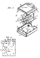
- FIGS. 4 and 5 illustrate one example of a physical embodiment of the adapter 30.
- the BNC coaxial connector 31 includes a post 50 which mounts the connector onto a printed circuit board 51 by soldering four legs of the post into holes (61-64 of FIG. 5) in the board. The signal portion of the contact is soldered in hole 65.
- Phono jacks 32 and 33 are mechanically attached to insulating blocks 52 and 53, respectively, which are snapped into holes (66, 67 and 68, 69, respectively) in the circuit board.
- Downwardly extending vertical posts (not shown) which are an integral part of the connectors 32 and 33 and couple the ground and signal portions to the board are soldered in holes 70, 71 and 72, 73 respectively, in the circuit board.
- each mounting position for the contacts includes the same array of nine holes so that the positions and types of contacts can be varied if desired.
- Each connector is coupled to its associated transformer (T1 -T3) by means of conductive leads, e.g., 75, formed on the bottom surface of the printed circuit board.
- Each transformer in turn, is coupled to its associated pins of modular jack 34 by conductive leads, e.g., 76, which are also deposited on the bottom surface of the printed circuit board.
- the pins of the modular jack 34 are soldered in their respective holes, e.g., 77.
- circuit board 51 and the components mounted thereon are enclosed within a housing formed by two half-shells, 80 and 81, mechanically attached by means of four posts (82-84 being visible) fitted within corresponding holes (85-87 being visible).
Landscapes
- Engineering & Computer Science (AREA)
- Signal Processing (AREA)
- Multimedia (AREA)
- Details Of Connecting Devices For Male And Female Coupling (AREA)
- Cable Transmission Systems, Equalization Of Radio And Reduction Of Echo (AREA)
- Closed-Circuit Television Systems (AREA)
- Coils Or Transformers For Communication (AREA)
- Details Of Television Systems (AREA)
- Coupling Device And Connection With Printed Circuit (AREA)
Applications Claiming Priority (2)
| Application Number | Priority Date | Filing Date | Title |
|---|---|---|---|
| US07/943,664 US5367273A (en) | 1992-09-11 | 1992-09-11 | Adapter for video and audio transmission |
| US943664 | 1992-09-11 |
Publications (2)
| Publication Number | Publication Date |
|---|---|
| EP0587367A1 true EP0587367A1 (de) | 1994-03-16 |
| EP0587367B1 EP0587367B1 (de) | 1998-07-29 |
Family
ID=25480052
Family Applications (1)
| Application Number | Title | Priority Date | Filing Date |
|---|---|---|---|
| EP93306904A Expired - Lifetime EP0587367B1 (de) | 1992-09-11 | 1993-09-01 | Anpassungsglied für Fernseh- und Tonsignalübertragung |
Country Status (6)
| Country | Link |
|---|---|
| US (1) | US5367273A (de) |
| EP (1) | EP0587367B1 (de) |
| JP (1) | JP3096542B2 (de) |
| KR (1) | KR100272018B1 (de) |
| CA (1) | CA2101222C (de) |
| HK (1) | HK1003215A1 (de) |
Cited By (3)
| Publication number | Priority date | Publication date | Assignee | Title |
|---|---|---|---|---|
| EP0690625A1 (de) * | 1994-06-29 | 1996-01-03 | AT&T Corp. | Schaltung zur Übertragung von Breitband-Video über ungeschirmte verdrillte Kabelpaare |
| GB2350039A (en) * | 1999-03-17 | 2000-11-15 | Adder Tech Ltd | Transmitting colour video signals via twisted pair lines |
| WO2006027144A1 (de) * | 2004-09-10 | 2006-03-16 | Adc Gmbh | Verteilermodul zur umsetzung zwischen symmetrischen und unsymmetrischen datenübertragungsstrecken |
Families Citing this family (13)
| Publication number | Priority date | Publication date | Assignee | Title |
|---|---|---|---|---|
| US6323894B1 (en) | 1993-03-12 | 2001-11-27 | Telebuyer, Llc | Commercial product routing system with video vending capability |
| US5495284A (en) | 1993-03-12 | 1996-02-27 | Katz; Ronald A. | Scheduling and processing system for telephone video communication |
| US20030185356A1 (en) | 1993-03-12 | 2003-10-02 | Telebuyer, Llc | Commercial product telephonic routing system with mobile wireless and video vending capability |
| US5537142A (en) * | 1993-10-20 | 1996-07-16 | Videolan Technologies, Inc. | Local area network for simultaneous, bi-directional transmission of video bandwidth signals, including a switching matrix which defines user connections, upstream connections, and downstream connections and has an efficient configuration to minimize the |
| US6137524A (en) * | 1995-10-30 | 2000-10-24 | Zekko Corporation | Transmitter and receiver circuits for transmission of voice, data and video signals for extended distances |
| US20020024591A1 (en) * | 1996-04-10 | 2002-02-28 | Igate, Incorporate | Local area network for simultaneous, bi-directional transmission of video bandwidth signals |
| US6636931B2 (en) * | 1998-01-06 | 2003-10-21 | Pragmatic Communications Systems, Inc. | System and method for switching signals over twisted-pair wires |
| US6823001B1 (en) | 2000-05-31 | 2004-11-23 | Bitrage, Inc. | Dual stage communication processor |
| US7149242B1 (en) | 2000-05-31 | 2006-12-12 | Bitrage, Inc. | Communications system for improving transmission rates and transmission distances of data signals across communications links |
| US20040151237A1 (en) * | 2000-05-31 | 2004-08-05 | Bitrage, Inc. | Satellite communications system |
| GB2359429B (en) * | 2001-01-19 | 2003-06-18 | Itt Mfg Enterprises Inc | Home entertainment system |
| AU2003278380A1 (en) * | 2002-06-19 | 2004-01-06 | The Siemon Company | Video balun |
| US8074255B2 (en) * | 2004-09-28 | 2011-12-06 | Clearcube Technology, Inc. | Analog video signal transmission over twisted-pair wires |
Citations (3)
| Publication number | Priority date | Publication date | Assignee | Title |
|---|---|---|---|---|
| FR2336017A1 (fr) * | 1975-12-18 | 1977-07-15 | Telediffusion Fse | Systeme commun de reseau de teledistribution et de reseau telephonique |
| DE3431994A1 (de) * | 1983-09-05 | 1985-04-04 | Olympus Optical Co., Ltd., Tokio/Tokyo | Rauschunterdrueckungseinrichtung fuer ein endoskop |
| WO1989003603A1 (en) * | 1987-10-14 | 1989-04-20 | The Boeing Company | Computer network interconnecting apparatus |
Family Cites Families (4)
| Publication number | Priority date | Publication date | Assignee | Title |
|---|---|---|---|---|
| US2099800A (en) * | 1936-02-04 | 1937-11-23 | American Telephone & Telegraph | Shielded circuits for open wire lines |
| JPS58172030A (ja) * | 1982-04-01 | 1983-10-08 | General Res Obu Erekutoronitsukusu:Kk | 広帯域信号の分配装置 |
| US4800344A (en) * | 1985-03-21 | 1989-01-24 | And Yet, Inc. | Balun |
| FR2634608B1 (fr) * | 1988-07-22 | 1994-05-06 | Etat Francais Cnet | Reseau domotique cable multipoints reconfigurable de distribution simultanee et/ou alternative de plusieurs types de signaux, notamment de signaux d'images en bande de base, et procede de configuration d'un tel reseau |
-
1992
- 1992-09-11 US US07/943,664 patent/US5367273A/en not_active Expired - Lifetime
-
1993
- 1993-07-23 CA CA002101222A patent/CA2101222C/en not_active Expired - Fee Related
- 1993-09-01 EP EP93306904A patent/EP0587367B1/de not_active Expired - Lifetime
- 1993-09-03 KR KR1019930017600A patent/KR100272018B1/ko not_active IP Right Cessation
- 1993-09-07 JP JP05246149A patent/JP3096542B2/ja not_active Expired - Fee Related
-
1998
- 1998-03-19 HK HK98102322A patent/HK1003215A1/xx not_active IP Right Cessation
Patent Citations (3)
| Publication number | Priority date | Publication date | Assignee | Title |
|---|---|---|---|---|
| FR2336017A1 (fr) * | 1975-12-18 | 1977-07-15 | Telediffusion Fse | Systeme commun de reseau de teledistribution et de reseau telephonique |
| DE3431994A1 (de) * | 1983-09-05 | 1985-04-04 | Olympus Optical Co., Ltd., Tokio/Tokyo | Rauschunterdrueckungseinrichtung fuer ein endoskop |
| WO1989003603A1 (en) * | 1987-10-14 | 1989-04-20 | The Boeing Company | Computer network interconnecting apparatus |
Non-Patent Citations (2)
| Title |
|---|
| E. BEEKMANN: "Allgemeine, praxisbezogene Betrachtung über die videofrequente Signalübertragung.", GRUNDIG TECHNISCHE INFORMATIONEN, vol. 22, no. 3, March 1975 (1975-03-01), FURTH DE, pages 566 - 572 * |
| N. NAKATANI ET AL: "A Hybrid Coax and Twisted Pair Home Bus.", 1986 IEEE INTERNATIONAL CONFERENCE ON CONSUMER ELECTRONICS. DIGEST OF TECHNICAL PAPERS. ICCE 86., 5 June 1986 (1986-06-05), pages 234 - 235 * |
Cited By (7)
| Publication number | Priority date | Publication date | Assignee | Title |
|---|---|---|---|---|
| EP0690625A1 (de) * | 1994-06-29 | 1996-01-03 | AT&T Corp. | Schaltung zur Übertragung von Breitband-Video über ungeschirmte verdrillte Kabelpaare |
| GB2350039A (en) * | 1999-03-17 | 2000-11-15 | Adder Tech Ltd | Transmitting colour video signals via twisted pair lines |
| US6618774B1 (en) | 1999-03-17 | 2003-09-09 | Adder Technology Ltd. | Computer signal transmission system |
| GB2350039B (en) * | 1999-03-17 | 2004-06-23 | Adder Tech Ltd | Computer signal transmission system |
| WO2006027144A1 (de) * | 2004-09-10 | 2006-03-16 | Adc Gmbh | Verteilermodul zur umsetzung zwischen symmetrischen und unsymmetrischen datenübertragungsstrecken |
| US7491093B2 (en) | 2004-09-10 | 2009-02-17 | Adc Gmbh | Distribution module for converting between symmetrical and asymmetrical data transmission paths |
| US7645168B2 (en) | 2004-09-10 | 2010-01-12 | Adc Gmbh | Distribution module for converting between symmetrical and asymmetrical data transmission paths |
Also Published As
| Publication number | Publication date |
|---|---|
| HK1003215A1 (en) | 1998-10-16 |
| KR100272018B1 (ko) | 2000-12-01 |
| KR940007839A (ko) | 1994-04-28 |
| CA2101222C (en) | 1998-09-15 |
| CA2101222A1 (en) | 1994-03-12 |
| JP3096542B2 (ja) | 2000-10-10 |
| EP0587367B1 (de) | 1998-07-29 |
| US5367273A (en) | 1994-11-22 |
| JPH06284042A (ja) | 1994-10-07 |
Similar Documents
| Publication | Publication Date | Title |
|---|---|---|
| US5367273A (en) | Adapter for video and audio transmission | |
| US5482469A (en) | Dual monitor self-contained six port digital signal cross-connect module | |
| US5864089A (en) | Low-crosstalk modular electrical connector assembly | |
| US5633614A (en) | Unbalanced to balanced signal line coupling device | |
| US5226835A (en) | Patch plug for cross-connect equipment | |
| AU696132B2 (en) | Circuit for broadband video transmission over unshielded twisted wire pairs | |
| EP1049217A1 (de) | Steckverbinder mit interner Nebensprechkompensation | |
| US6462637B1 (en) | Electrical connector | |
| EP0608251B1 (de) | Elektrischer stecker-modul für multi media, breitband- und niederfrequenzkabel | |
| AU678468B2 (en) | Autotransformer for the transmission of baseband video | |
| JPH09274972A (ja) | ビデオ信号伝送用接続器、並びに該接続器を備えたビデオ信号伝送装置及びビデオ信号伝送システム | |
| US5705961A (en) | Induction device for high radio frequency signal distributor | |
| US5389900A (en) | Adapter for transmission of color components on separate twisted wire pairs | |
| US11336065B2 (en) | Network jack with secure connector and magnetics | |
| US4787862A (en) | Apparatus for electrically connecting two audio components utilizing different sized conductors | |
| JPH0710066B2 (ja) | 単一通信路システム | |
| JPH079453Y2 (ja) | 分岐器 | |
| US20020159612A1 (en) | Personal computer audio interface device and method of using the same | |
| JPH053415A (ja) | インピーダンス整合器 | |
| CA2114500A1 (en) | Apparatus and method for cross-talk reduction | |
| EP0801404A1 (de) | Induktivität für hochfrequenz Signalverteiler | |
| JPH08236217A (ja) | モジュラプラグ |
Legal Events
| Date | Code | Title | Description |
|---|---|---|---|
| PUAI | Public reference made under article 153(3) epc to a published international application that has entered the european phase |
Free format text: ORIGINAL CODE: 0009012 |
|
| AK | Designated contracting states |
Kind code of ref document: A1 Designated state(s): FR GB IT NL |
|
| RAP3 | Party data changed (applicant data changed or rights of an application transferred) |
Owner name: AT&T CORP. |
|
| 17P | Request for examination filed |
Effective date: 19940902 |
|
| 17Q | First examination report despatched |
Effective date: 19961216 |
|
| GRAG | Despatch of communication of intention to grant |
Free format text: ORIGINAL CODE: EPIDOS AGRA |
|
| GRAG | Despatch of communication of intention to grant |
Free format text: ORIGINAL CODE: EPIDOS AGRA |
|
| GRAH | Despatch of communication of intention to grant a patent |
Free format text: ORIGINAL CODE: EPIDOS IGRA |
|
| GRAH | Despatch of communication of intention to grant a patent |
Free format text: ORIGINAL CODE: EPIDOS IGRA |
|
| GRAA | (expected) grant |
Free format text: ORIGINAL CODE: 0009210 |
|
| AK | Designated contracting states |
Kind code of ref document: B1 Designated state(s): FR GB IT NL |
|
| ITF | It: translation for a ep patent filed |
Owner name: JACOBACCI & PERANI S.P.A. |
|
| ET | Fr: translation filed | ||
| PLBE | No opposition filed within time limit |
Free format text: ORIGINAL CODE: 0009261 |
|
| STAA | Information on the status of an ep patent application or granted ep patent |
Free format text: STATUS: NO OPPOSITION FILED WITHIN TIME LIMIT |
|
| 26N | No opposition filed | ||
| REG | Reference to a national code |
Ref country code: GB Ref legal event code: IF02 |
|
| PGFP | Annual fee paid to national office [announced via postgrant information from national office to epo] |
Ref country code: FR Payment date: 20080915 Year of fee payment: 16 Ref country code: NL Payment date: 20080903 Year of fee payment: 16 Ref country code: IT Payment date: 20080926 Year of fee payment: 16 |
|
| PGFP | Annual fee paid to national office [announced via postgrant information from national office to epo] |
Ref country code: GB Payment date: 20090929 Year of fee payment: 17 |
|
| REG | Reference to a national code |
Ref country code: NL Ref legal event code: V1 Effective date: 20100401 |
|
| REG | Reference to a national code |
Ref country code: FR Ref legal event code: ST Effective date: 20100531 |
|
| PG25 | Lapsed in a contracting state [announced via postgrant information from national office to epo] |
Ref country code: NL Free format text: LAPSE BECAUSE OF NON-PAYMENT OF DUE FEES Effective date: 20100401 Ref country code: FR Free format text: LAPSE BECAUSE OF NON-PAYMENT OF DUE FEES Effective date: 20090930 |
|
| PG25 | Lapsed in a contracting state [announced via postgrant information from national office to epo] |
Ref country code: IT Free format text: LAPSE BECAUSE OF NON-PAYMENT OF DUE FEES Effective date: 20090901 |
|
| GBPC | Gb: european patent ceased through non-payment of renewal fee |
Effective date: 20100901 |
|
| PG25 | Lapsed in a contracting state [announced via postgrant information from national office to epo] |
Ref country code: GB Free format text: LAPSE BECAUSE OF NON-PAYMENT OF DUE FEES Effective date: 20100901 |