EP0587146A2 - Méthode et appareil pour déterminer l'état de chargement de filtres à particules - Google Patents
Méthode et appareil pour déterminer l'état de chargement de filtres à particules Download PDFInfo
- Publication number
- EP0587146A2 EP0587146A2 EP93114429A EP93114429A EP0587146A2 EP 0587146 A2 EP0587146 A2 EP 0587146A2 EP 93114429 A EP93114429 A EP 93114429A EP 93114429 A EP93114429 A EP 93114429A EP 0587146 A2 EP0587146 A2 EP 0587146A2
- Authority
- EP
- European Patent Office
- Prior art keywords
- filter
- characteristic value
- pressure
- measuring device
- particle filter
- Prior art date
- Legal status (The legal status is an assumption and is not a legal conclusion. Google has not performed a legal analysis and makes no representation as to the accuracy of the status listed.)
- Granted
Links
Images


Classifications
-
- B—PERFORMING OPERATIONS; TRANSPORTING
- B01—PHYSICAL OR CHEMICAL PROCESSES OR APPARATUS IN GENERAL
- B01D—SEPARATION
- B01D46/00—Filters or filtering processes specially modified for separating dispersed particles from gases or vapours
- B01D46/42—Auxiliary equipment or operation thereof
- B01D46/44—Auxiliary equipment or operation thereof controlling filtration
- B01D46/46—Auxiliary equipment or operation thereof controlling filtration automatic
-
- F—MECHANICAL ENGINEERING; LIGHTING; HEATING; WEAPONS; BLASTING
- F01—MACHINES OR ENGINES IN GENERAL; ENGINE PLANTS IN GENERAL; STEAM ENGINES
- F01N—GAS-FLOW SILENCERS OR EXHAUST APPARATUS FOR MACHINES OR ENGINES IN GENERAL; GAS-FLOW SILENCERS OR EXHAUST APPARATUS FOR INTERNAL COMBUSTION ENGINES
- F01N11/00—Monitoring or diagnostic devices for exhaust-gas treatment apparatus, e.g. for catalytic activity
- F01N11/002—Monitoring or diagnostic devices for exhaust-gas treatment apparatus, e.g. for catalytic activity the diagnostic devices measuring or estimating temperature or pressure in, or downstream of the exhaust apparatus
-
- F—MECHANICAL ENGINEERING; LIGHTING; HEATING; WEAPONS; BLASTING
- F01—MACHINES OR ENGINES IN GENERAL; ENGINE PLANTS IN GENERAL; STEAM ENGINES
- F01N—GAS-FLOW SILENCERS OR EXHAUST APPARATUS FOR MACHINES OR ENGINES IN GENERAL; GAS-FLOW SILENCERS OR EXHAUST APPARATUS FOR INTERNAL COMBUSTION ENGINES
- F01N3/00—Exhaust or silencing apparatus having means for purifying, rendering innocuous, or otherwise treating exhaust
- F01N3/02—Exhaust or silencing apparatus having means for purifying, rendering innocuous, or otherwise treating exhaust for cooling, or for removing solid constituents of, exhaust
- F01N3/021—Exhaust or silencing apparatus having means for purifying, rendering innocuous, or otherwise treating exhaust for cooling, or for removing solid constituents of, exhaust by means of filters
- F01N3/023—Exhaust or silencing apparatus having means for purifying, rendering innocuous, or otherwise treating exhaust for cooling, or for removing solid constituents of, exhaust by means of filters using means for regenerating the filters, e.g. by burning trapped particles
- F01N3/025—Exhaust or silencing apparatus having means for purifying, rendering innocuous, or otherwise treating exhaust for cooling, or for removing solid constituents of, exhaust by means of filters using means for regenerating the filters, e.g. by burning trapped particles using fuel burner or by adding fuel to exhaust
-
- F—MECHANICAL ENGINEERING; LIGHTING; HEATING; WEAPONS; BLASTING
- F01—MACHINES OR ENGINES IN GENERAL; ENGINE PLANTS IN GENERAL; STEAM ENGINES
- F01N—GAS-FLOW SILENCERS OR EXHAUST APPARATUS FOR MACHINES OR ENGINES IN GENERAL; GAS-FLOW SILENCERS OR EXHAUST APPARATUS FOR INTERNAL COMBUSTION ENGINES
- F01N9/00—Electrical control of exhaust gas treating apparatus
- F01N9/002—Electrical control of exhaust gas treating apparatus of filter regeneration, e.g. detection of clogging
-
- G—PHYSICS
- G01—MEASURING; TESTING
- G01M—TESTING STATIC OR DYNAMIC BALANCE OF MACHINES OR STRUCTURES; TESTING OF STRUCTURES OR APPARATUS, NOT OTHERWISE PROVIDED FOR
- G01M13/00—Testing of machine parts
-
- F—MECHANICAL ENGINEERING; LIGHTING; HEATING; WEAPONS; BLASTING
- F01—MACHINES OR ENGINES IN GENERAL; ENGINE PLANTS IN GENERAL; STEAM ENGINES
- F01N—GAS-FLOW SILENCERS OR EXHAUST APPARATUS FOR MACHINES OR ENGINES IN GENERAL; GAS-FLOW SILENCERS OR EXHAUST APPARATUS FOR INTERNAL COMBUSTION ENGINES
- F01N2550/00—Monitoring or diagnosing the deterioration of exhaust systems
- F01N2550/04—Filtering activity of particulate filters
-
- F—MECHANICAL ENGINEERING; LIGHTING; HEATING; WEAPONS; BLASTING
- F02—COMBUSTION ENGINES; HOT-GAS OR COMBUSTION-PRODUCT ENGINE PLANTS
- F02B—INTERNAL-COMBUSTION PISTON ENGINES; COMBUSTION ENGINES IN GENERAL
- F02B3/00—Engines characterised by air compression and subsequent fuel addition
- F02B3/06—Engines characterised by air compression and subsequent fuel addition with compression ignition
-
- F—MECHANICAL ENGINEERING; LIGHTING; HEATING; WEAPONS; BLASTING
- F02—COMBUSTION ENGINES; HOT-GAS OR COMBUSTION-PRODUCT ENGINE PLANTS
- F02D—CONTROLLING COMBUSTION ENGINES
- F02D2200/00—Input parameters for engine control
- F02D2200/02—Input parameters for engine control the parameters being related to the engine
- F02D2200/08—Exhaust gas treatment apparatus parameters
- F02D2200/0812—Particle filter loading
-
- Y—GENERAL TAGGING OF NEW TECHNOLOGICAL DEVELOPMENTS; GENERAL TAGGING OF CROSS-SECTIONAL TECHNOLOGIES SPANNING OVER SEVERAL SECTIONS OF THE IPC; TECHNICAL SUBJECTS COVERED BY FORMER USPC CROSS-REFERENCE ART COLLECTIONS [XRACs] AND DIGESTS
- Y02—TECHNOLOGIES OR APPLICATIONS FOR MITIGATION OR ADAPTATION AGAINST CLIMATE CHANGE
- Y02T—CLIMATE CHANGE MITIGATION TECHNOLOGIES RELATED TO TRANSPORTATION
- Y02T10/00—Road transport of goods or passengers
- Y02T10/10—Internal combustion engine [ICE] based vehicles
- Y02T10/40—Engine management systems
Definitions
- the invention relates to a method for determining the loading state of a particle filter used in the exhaust system of a diesel engine, in particular used in a motor vehicle, and a device for carrying out the method.
- the particle filters increasingly used for exhaust gas cleaning in diesel engines which in addition to filtering out other harmful gas components of the engine exhaust gas, in particular for filtering out soot particles carried in the exhaust gas, must be subjected to frequent cleaning (regeneration) in order to maintain their functionality.
- the thermal regeneration of particle filters has proven to be effective, in which the soot particles contained in the particle filter are ignited and burned by introducing high-temperature heating gases (approximately 600 ° C to 900 ° C).
- a heating gas flow generated by an engine-independent heating device is mixed with the engine exhaust gas in the particle filter which is permanently in the exhaust gas flow for the time of regeneration, and is introduced together with the latter into the particle filter in order to achieve the aforementioned to reach the gas temperature required for regeneration.
- the manufacturers of particle filters specify certain, fixed operating intervals in which thermal regeneration takes place is to be carried out.
- the regeneration intervals are chosen so that even under extreme operating conditions of the engine, such as frequent short-distance operation with extreme soot formation in the engine exhaust gases, sufficient safety is provided in the intervals so that the regeneration in any case before the occurrence the described harmful effects can occur.
- the regeneration of a particulate filter inevitably takes place when the engine is low in soot at a time when it would not be necessary at all.
- the invention is based on the object of proposing a method and a device which enables a simple determination of the actually given loading state of a particle filter, taking into account the given engine operating conditions.
- the measurement of at least one filter-specific, thermodynamic variable which characterizes the state of the exhaust gas volume flow and its assignment to a measured engine-specific variable, which is proportional to the volume flow creates a simple relationship between measured values, which determines the determination of the actual state of charge of the particle filter. Characteristic value enabled. By comparison with an empirically determined limit characteristic value, the deviation of the actual characteristic value from the limit characteristic value can be recorded as a difference in order to initiate a regeneration process if the difference is sufficiently small, the size of which can by definition lie between zero and any value.
- the limit value can be specified, for example, as the limit characteristic curve determined in test bench tests, taking into account different loading conditions and volume flows.
- the permissible limit value is determined as a function of the level of the permitted torque drop, which arises as a result of the exhaust gas back pressure caused by the particle filter in the exhaust system.
- the determination of the actual characteristic value proves to be particularly reliable if two filter-specific parameters, namely a pressure value and a temperature value, and the engine speed are measured as an engine-specific parameter.
- the pressure in front of the particle filter i.e. the filter pre-pressure
- the pressure drop across the particle filter i.e. the differential pressure measured on the particle filter
- the average volume flow temperature in the particle filter are used as the temperature value of the exhaust gas volume flow.
- a method expanded according to claim 4 by the acquisition and processing of additional measured values particularly advantageously enables the determination of the loading state of a particle filter which is arranged in the exhaust system of a diesel engine provided with an exhaust gas charge.
- filter-specific parameters namely the pressure upstream of the particle filter, the pressure drop across the particle filter and the temperature of the exhaust gas volume flow in the particle filter
- specific parameters of the charge volume flow namely the temperature and pressure of the charge volume flow, are also used to determine the actual characteristic value of the Load condition taken into account.
- a display device is preferably activated which, for example when the method according to the invention is used in a motor vehicle, by the motor vehicle driver critical loading state of the particle filter. The latter can then initiate regeneration of the particle filter in accordance with one of the regeneration methods described above.
- Another possibility is to couple the display device to a start device for automatically triggering one of the regeneration processes described, or to trigger the start device directly even if a critical difference value is determined, without first displaying the value.
- a display device it proves to be particularly advantageous to display the actual characteristic value, ascertained in the method according to the invention, continuously or at predetermined time intervals, based on an initial characteristic value having a defined difference from the limit characteristic value, in order to indicate the progress of the loading state to make it visible from the outside, so that the necessity of performing a particle filter regeneration can be recognized in advance.
- the device according to the invention for determining the loading state of a particle filter used in the exhaust system of a diesel engine, in particular used in a motor vehicle, has the features of claim 7.
- the device according to the invention has a differential pressure measuring device which detects the pressure drop in the exhaust gas volume flow via the particle filter or a filter pre-pressure arranged in front of the particle filter measuring pressure measuring device. Also in the area of the particle filter is a temperature measuring device that detects the temperature of the exhaust gas volume flow. A motor measuring device is provided as a further measuring device for detecting a volume-specific, motor-specific variable. In order to form an actual characteristic value by means of the measured values detected by the above-mentioned measuring devices, a computing device is provided which also enables a comparison of the actual characteristic value determined in this way with a predetermined limit characteristic value. Finally, the device according to the invention can also have a display device which serves to indicate when the limit characteristic value has been reached and / or the difference between the actual characteristic value and the limit characteristic value determined by the comparison in the computing device.
- the display device is designed such that it only indicates that the limit characteristic value has been reached, the signal is given to the motor vehicle driver to carry out a regeneration process in the particle filter.
- the motor vehicle driver has the possibility of constantly being informed about the progress of the loading condition and to a certain extent determining the time for carrying out a regeneration himself.
- the device according to claim 9 is an embodiment variant of the device according to the invention, which enables a particularly advantageous use in determining the loading state of a particle filter that is charged in the exhaust system Diesel engine is arranged.
- the measuring devices for measuring filter-specific quantities namely a differential pressure measuring device, a pressure measuring device measuring the filter admission pressure and a temperature measuring device, and a measuring device for detecting a volume-flow-proportional, motor-specific quantity
- there are also measuring devices for measuring specific quantities of the loading volume flow namely a temperature of the loading volume flow temperature measuring device and a pressure measuring device detecting the pressure of the loading volume flow are provided.
- FIG. 1 shows a particle filter 10 which is arranged in an exhaust system 11 of a diesel engine 12 operated as a naturally aspirated engine.
- the particle filter 10 is connected via flange connections 13, 14 on its input side to a prechamber 15 and on its output side to a reducer 16.
- the antechamber 15 is connected to the diesel engine 12 via an exhaust pipe 17.
- the reducer 16 merges downstream into an exhaust pipe 18 through which the engine exhaust gases are discharged in the direction of the free end of the exhaust system 11.
- An air flow 22 fed to the diesel engine 12 through an intake line 21 is burned in the system in the diesel engine 12 schematically shown in FIG.
- a combustion chamber 19 is provided for the regeneration of the particle filter 10, which is used for heating a gas stream introduced into this through a feed 20 is used. During regeneration, the gas stream introduced through the feed 20 is heated in the combustion chamber 19 to achieve the exhaust gas temperature required for the regeneration and mixed with the exhaust gas stream flowing into the prechamber 14 through the exhaust pipe 17.
- a differential pressure measuring device 24 In the area of the particle filter 10, a differential pressure measuring device 24 is provided, which in the exemplary embodiment shown here has two measuring sensors 25, 26.
- the sensor 25 is provided for measuring the pressure in the exhaust gas volume flow before entering the particle filter and the sensor 26 for measuring the pressure in the exhaust gas volume flow after exiting the particle filter 10.
- the differential pressure measuring device 24 determines in a known manner the differential pressure prevailing between the installation locations of the sensors 25, 26, that is to say the pressure drop across the particle filter 10.
- the sensor 25 arranged upstream of the particle filter 10 serves to describe the state of the exhaust gas at the filter inlet.
- a temperature measuring device 27 provided with sensors 37, 38 is provided as a further measuring device in the area of the particle filter 10, by means of which the mean temperature of the exhaust gas volume flow in the particle filter 10 can be determined.
- a speed measuring device 28 connected to the diesel engine 12 is provided.
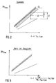
- the upper of the two graphs shown in FIG. 2 shows the limit value for the loading of the particle filter, which is constantly defined by the gradient of the graph.
- This limit value GK can be determined, for example, in test bench tests, the limit value for the loading condition of the particle filter being determined, for example, as a function of the permissible power loss of the diesel engine due to the clogging of the particle filter with soot particles and the like.
- the second, lower graph represents the unloaded state of the particle filter in comparison to the maximum permissible load state represented by the upper graph.
- thermodynamic variables ⁇ p filter and t m, filter and the engine speed n shown in FIG. 2 it is therefore possible to determine whether the operating point of the particle filter defined by the above variables with the permissible loading limit GK maximum permissible loading condition has been reached or how far the current loading condition of the particle filter defined by the operating point is from the permissible loading condition.
- an actual characteristic value IK characterizing the current loading condition that is the operating point of the particle filter
- FIG. 2 there is an actual difference DI at this operating point of the particle filter between the limit characteristic value GK and the actual characteristic value IK.
- the maximum loading condition has therefore not yet been reached in this point. This means that regeneration of the particle filter does not have to be initiated yet. This is only the case when the actual characteristic value IK is equal to the limit characteristic value GK.
- thermodynamic variables .DELTA.p filter and t m, filter ascertained by means of the measuring devices 24, 27, 28 shown in FIG. 1 and the engine speed n proportional to the volume flow are transferred to a computing device 29.
- the computing device 29 first calculates the actual characteristic value as the quotient of the filter differential pressure ⁇ p filter and the product of the engine speed n and the average filter temperature t m, filter .
- the actual difference DI between the calculated actual characteristic value IK and the limit characteristic value GK is then formed and displayed.
- the check is carried out to determine whether the actual difference DI is smaller than a predetermined target difference DS. In the affirmative, the regeneration device is then started, that is to say the combustion chamber 19 shown in FIG. 1 is started.
- FIG. 4 shows a particle filter 10, which in the exhaust system 11 is provided with an exhaust gas charger 30 Diesel engine 12 is arranged.
- the components of the exhaust system 11 shown in FIG. 4 which correspond to the components in FIG. 1 , have the same reference numerals as in FIG. 1 .
- the exhaust gas charger 30 upstream of the diesel engine 12 is provided in FIG .
- the exhaust gas charger 30 essentially consists of a compressor 31 connected into the intake line 21, which is driven by an exhaust gas turbine 32 which is coupled to the compressor 31 and is arranged in the exhaust pipe 17.
- An intercooler 33 can optionally be provided between the compressor 31 of the exhaust gas charger 30 and the inlet to the diesel engine 12 in the intake line 21.
- a pressure measuring device 34 for measuring the pressure in the volume flow at the engine inlet p ME and a temperature measuring device 35 for measuring the temperature t ME of the volume flow 22 entering the diesel engine 12 in the intake line 21, directly upstream of the engine input.
- a pressure measuring device 36 which detects the filter pre-pressure p upstream of the filter is arranged.
- the pressure measuring device 36 can also be formed from the sensor 25 of the differential pressure measuring device 24, so that the pressure measuring device 36 virtually one Forms part of the differential pressure measuring device 24.
- the diagram shown in FIG. 5 shows the determined linear relationship between the filter differential pressure ⁇ p filter and the mean filter temperature t m, filter and the volume flow introduced into the diesel engine. Due to the compression of the volume flow introduced into the diesel engine 12 by the exhaust gas charger 30, the volume flow proportional quantity plotted along the abscissa in FIG. 5 is not solely speed-dependent (as shown in FIG. 2 ), but is also determined by the quotient from the engine inlet pressure p ME and the product of the engine inlet temperature t ME and the filter pre-pressure p pre-filter .
- FIG. 6 shows on the basis of a flow diagram how a method for determining the loading state of a particle filter which is arranged in the exhaust system of a diesel engine provided with an exhaust gas charger can be carried out.
- the measured values acquired by means of the measuring devices shown in FIG. 4 namely the engine speed n, the filter differential pressure ⁇ p filter , the mean filter temperature t m, filters , the engine inlet pressure p ME , the engine inlet temperature t ME and the filter pre-pressure p before filter to the computing device 29 to hand over.
- the computing operation shown in FIG. 6 is carried out to calculate the actual characteristic value IK.
- the further sequence shown in FIG. 6 corresponds to the sequence shown in FIG. 3 after calculation of the actual characteristic value IK, so that reference is made to the description of FIG. 3 for further explanation.
Applications Claiming Priority (2)
| Application Number | Priority Date | Filing Date | Title |
|---|---|---|---|
| DE4230180 | 1992-09-09 | ||
| DE4230180A DE4230180A1 (de) | 1992-09-09 | 1992-09-09 | Verfahren und Vorrichtung zur Ermittlung des Beladungszustands von Partikelfiltern |
Publications (3)
| Publication Number | Publication Date |
|---|---|
| EP0587146A2 true EP0587146A2 (fr) | 1994-03-16 |
| EP0587146A3 EP0587146A3 (en) | 1994-08-24 |
| EP0587146B1 EP0587146B1 (fr) | 1997-03-05 |
Family
ID=6467616
Family Applications (1)
| Application Number | Title | Priority Date | Filing Date |
|---|---|---|---|
| EP93114429A Expired - Lifetime EP0587146B1 (fr) | 1992-09-09 | 1993-09-08 | Appareil pour déterminer l'état de chargement de filtres à particules |
Country Status (5)
| Country | Link |
|---|---|
| US (1) | US5511413A (fr) |
| EP (1) | EP0587146B1 (fr) |
| JP (1) | JPH0791227A (fr) |
| AT (1) | ATE149634T1 (fr) |
| DE (2) | DE4230180A1 (fr) |
Cited By (5)
| Publication number | Priority date | Publication date | Assignee | Title |
|---|---|---|---|---|
| WO1999028010A1 (fr) * | 1997-12-04 | 1999-06-10 | Elkem Asa | Procede de regulation de la pression de l'air inverse dans des sacs-filtres |
| FR2781251A1 (fr) | 1998-07-20 | 2000-01-21 | Renault | Procede et dispositif de determination du chargement en suies d'un filtre a particules |
| EP1281843A2 (fr) * | 2001-08-01 | 2003-02-05 | Renault s.a.s. | Procédé de détermination du chargement d'un filtre à particules |
| DE10260784A1 (de) * | 2002-12-23 | 2004-07-01 | Daimlerchrysler Ag | Verfahren zur Überwachung des Verschmutzungsgrades einer Filtereinrichtung |
| WO2008059166A1 (fr) | 2006-11-17 | 2008-05-22 | Saint-Gobain Centre De Recherches Et D'etudes Europeen | Procede de calibrage et de gestion d'une ligne d'echappement comprenant un filtre a particules |
Families Citing this family (57)
| Publication number | Priority date | Publication date | Assignee | Title |
|---|---|---|---|---|
| DE4416541A1 (de) * | 1994-05-10 | 1995-11-16 | Brueckner Trockentechnik Gmbh | Verfahren und Vorrichtung zur Reinigung eines Umluftstromes |
| US5606311A (en) * | 1995-08-30 | 1997-02-25 | General Motors Corporation | Air filter diagnostic |
| US5670714A (en) * | 1996-03-27 | 1997-09-23 | Sorensen; Jens O. | Air-pollution reduction method and system for the interior of an automobile |
| DE19720577A1 (de) * | 1997-05-16 | 1998-11-19 | Bernd Grunwald | Differenzdruck-Meßgerät |
| DE19740327A1 (de) * | 1997-09-13 | 1999-03-18 | Univ Karlsruhe | Verfahren und Vorrichtung zur Probenaufbereitung für die Analytik partikelhaltiger wäßriger Proben |
| AT2410U1 (de) * | 1997-09-16 | 1998-10-27 | Avl List Gmbh | Verfahren zur regeneration eines partikelfilters |
| US6968682B1 (en) | 1999-05-07 | 2005-11-29 | Robert Bosch Gmbh | Method and device for controlling an internal combustion engine with an exhaust treatment system |
| US6377171B1 (en) | 1999-09-15 | 2002-04-23 | Peerless Mfg. Co. | On-line filter monitoring system |
| DE19949502A1 (de) | 1999-10-14 | 2001-04-19 | Volkswagen Ag | Verfahren zur Ermittlung des Beladungswertes eines Partikelfilters in Verbrennungskraftmaschinen, insbesondere Dieselmotoren |
| DE19951962A1 (de) * | 1999-10-28 | 2001-05-03 | Festo Ag & Co | Filtergerät zum Filtern von Druckluft |
| DE10062022B4 (de) * | 1999-12-14 | 2014-11-20 | Toyota Jidosha Kabushiki Kaisha | Vorrichtung zum Erfassen eines Fehlers in einem Abgassystem eines Motors |
| US6408686B1 (en) * | 2000-01-07 | 2002-06-25 | Ford Global Technologies, Inc. | Exhaust system monitor |
| DE10017361A1 (de) * | 2000-04-07 | 2001-10-11 | Mann & Hummel Filter | Differenzdruck-Messanordnung |
| GB2397134B (en) * | 2000-08-25 | 2004-12-29 | Ford Global Tech Llc | Monitoring of a diesel particulate filter |
| US6397587B1 (en) * | 2000-08-25 | 2002-06-04 | Frod Global Tech., Inc. | System and method for monitoring the loading of a diesel particulate filter |
| FR2814498B1 (fr) * | 2000-09-27 | 2003-04-11 | Renault | Procede de gestion du fonctionnement d'un filtre a particules pour moteur a combustion |
| FR2817286B1 (fr) * | 2000-11-24 | 2003-01-24 | Renault | Procede de regeneration d'un filtre a particules |
| DE10059683B4 (de) * | 2000-12-01 | 2007-10-04 | Audi Ag | Verfahren zur Überwachung eines Partikelfiltersystems im Abgasstrang einer Brennkraftmaschine |
| FR2832758B1 (fr) * | 2001-11-29 | 2004-01-30 | Renault | Procede et dispositif de diagnostic de l'etat de fonctionnement d'une ligne d'echappement d'un moteur a combustion interne |
| ITTO20020072A1 (it) * | 2002-01-25 | 2003-07-25 | Fiat Ricerche | Metodo per la determinazione della quantita' di particolato accumulata in un filtro per particolato. |
| FR2836956B1 (fr) * | 2002-03-08 | 2004-09-17 | Renault | Procede de regeneration de filtre a particules pour vehicule automobile |
| US6651638B1 (en) | 2002-06-28 | 2003-11-25 | Cummins Engine Company, Inc. | System and method for derating an engine to encourage servicing of a vehicle |
| US6948486B2 (en) * | 2002-06-28 | 2005-09-27 | Fleetguard, Inc. | System and method for derating an engine to encourage servicing of a vehicle |
| DE10248431A1 (de) * | 2002-10-17 | 2004-04-29 | Robert Bosch Gmbh | Verfahren zur Erkennung der Beladung eines Partikelfilters |
| JP4140371B2 (ja) * | 2002-12-16 | 2008-08-27 | 日産自動車株式会社 | パティキュレートフィルタの再生装置及びエンジンの排気ガス浄化装置 |
| JP2004197657A (ja) * | 2002-12-18 | 2004-07-15 | Nissan Motor Co Ltd | パティキュレートフィルタの再生装置及びエンジンの排気ガス浄化装置 |
| DE10301035A1 (de) * | 2003-01-13 | 2004-07-22 | Hjs Fahrzeugtechnik Gmbh & Co. | Verfahren zum Regeln der Ansteuerung einer Heizeinrichtung zum Regenerieren eines in den Abgasstrang einer Brennkraftmaschine eingeschalteten Partikelfilters |
| JP3750664B2 (ja) * | 2003-03-07 | 2006-03-01 | 日産自動車株式会社 | エンジンの排気浄化装置 |
| US6871489B2 (en) * | 2003-04-16 | 2005-03-29 | Arvin Technologies, Inc. | Thermal management of exhaust systems |
| US6978604B2 (en) * | 2003-11-06 | 2005-12-27 | International Engine Intellectual Property Company, Llc | Soot burn-off control strategy for a catalyzed diesel particulate filter |
| US6993414B2 (en) * | 2003-12-18 | 2006-01-31 | Carrier Corporation | Detection of clogged filter in an HVAC system |
| JP4038187B2 (ja) * | 2004-03-11 | 2008-01-23 | トヨタ自動車株式会社 | 内燃機関排気浄化装置の粒子状物質再生制御装置 |
| DE102004025436A1 (de) * | 2004-05-24 | 2005-12-29 | Umicore Ag & Co. Kg | Virtueller Beladungssensor |
| JP4470593B2 (ja) * | 2004-06-03 | 2010-06-02 | 株式会社デンソー | 内燃機関の排気浄化装置 |
| FR2872213B1 (fr) * | 2004-06-23 | 2006-11-03 | Peugeot Citroen Automobiles Sa | Systeme d'aide a la regeneration de moyens de depollution pour moteur de vehicule automobile |
| FR2872212B1 (fr) * | 2004-06-23 | 2006-11-03 | Peugeot Citroen Automobiles Sa | Systeme d'evaluation de l'etat de charge de moyens de depollution d'une ligne d'echappement |
| FR2872214B1 (fr) | 2004-06-23 | 2006-11-03 | Peugeot Citroen Automobiles Sa | Systeme de controle de la regeneration de moyens de depollution |
| US7445705B2 (en) * | 2004-08-19 | 2008-11-04 | Ford Motor Company | Particle filter for fuel cell coolant |
| US20060254260A1 (en) * | 2005-05-16 | 2006-11-16 | Arvinmeritor Emissions Technologies Gmbh | Method and apparatus for piezoelectric injection of agent into exhaust gas for use with emission abatement device |
| US7332142B2 (en) * | 2005-06-17 | 2008-02-19 | Emcon Tehnologies Germany (Augsburg) Gmbh | Method and apparatus for bubble injection of agent into exhaust gas for use with emission abatement device |
| US7406822B2 (en) * | 2005-06-30 | 2008-08-05 | Caterpillar Inc. | Particulate trap regeneration system and control strategy |
| US8209962B2 (en) * | 2005-09-28 | 2012-07-03 | Detroit Diesel Corporation | Diesel particulate filter soot permeability virtual sensors |
| DE102006000845A1 (de) * | 2006-01-05 | 2007-07-12 | Volkswagen Ag | Verfahren zur Bestimmung der Russbeladung eines Partikelfilters |
| DE102007003153B4 (de) * | 2007-01-22 | 2011-01-05 | Continental Automotive Gmbh | Verfahren zur Plausibilisierung eines ermittelten Differenzdruckwerts über einen Partikelfilter |
| US8011180B2 (en) * | 2007-08-16 | 2011-09-06 | Ford Global Technologies, Llc | Particulate filter regeneration |
| DE102007057039A1 (de) | 2007-11-27 | 2009-05-28 | Robert Bosch Gmbh | Verfahren zur Erkennung der Beladung eines Partikelfilters |
| FR2927659B1 (fr) * | 2008-02-14 | 2013-02-01 | Renault Sas | Estimation du chargement d'un filtre a particules |
| US8146351B2 (en) * | 2009-06-05 | 2012-04-03 | GM Global Technology Operations LLC | Regeneration systems and methods for particulate filters using virtual brick temperature sensors |
| DE102009060509A1 (de) | 2009-12-23 | 2011-06-30 | MTU Friedrichshafen GmbH, 88045 | Verfahren zur Regeneration eines Partikelfilters |
| US20130204508A1 (en) * | 2012-02-08 | 2013-08-08 | GM Global Technology Operations LLC | System and method for controlling an engine |
| DE102015211151B4 (de) * | 2015-06-17 | 2021-08-12 | Vitesco Technologies GmbH | Verfahren und Vorrichtung zur Ermittlung des Beladungszustands eines Abgaspartikelfilters |
| DE102015221495A1 (de) | 2015-11-03 | 2017-05-04 | Volkswagen Aktiengesellschaft | Verfahren und Vorrichtung zur Regeneration eines Partikelfilters |
| DE102017104469A1 (de) * | 2017-03-03 | 2018-09-06 | Volkswagen Aktiengesellschaft | Verfahren zum Ermitteln des Beladungszustands eines Partikelfilters und Verbrennungsmotor |
| FR3070728B1 (fr) * | 2017-09-06 | 2019-08-30 | Psa Automobiles Sa | Procede de protection d’un filtre a particules dans une ligne d’echappement pendant une regeneration |
| CN109538333B (zh) * | 2018-09-17 | 2021-09-14 | 广东工业大学 | 柴油机排气颗粒捕集器再生时刻的判定方法 |
| CN113606025B (zh) * | 2021-08-20 | 2022-11-22 | 一汽解放汽车有限公司 | 一种用于柴油机dpf捕集效率故障诊断方法 |
| AT525634B1 (de) * | 2022-07-11 | 2023-06-15 | Aigner Gmbh | Verfahren zur Veränderung des Volumenstroms eines gasförmigen Fluids |
Citations (4)
| Publication number | Priority date | Publication date | Assignee | Title |
|---|---|---|---|---|
| EP0220484A2 (fr) * | 1985-10-26 | 1987-05-06 | MAN Technologie Aktiengesellschaft | Moteur diesel comprenant un filtre de suie |
| EP0260031A1 (fr) * | 1986-08-28 | 1988-03-16 | AlliedSignal Inc. | Système de régénération d'un piège à particules pour moteurs |
| EP0411445A2 (fr) * | 1989-08-02 | 1991-02-06 | Cummins Engine Company, Inc. | Système de régénération de filtre à particules |
| EP0446400A1 (fr) * | 1988-09-27 | 1991-09-18 | Konstantin N. Prof.Dr.-Ing. Pattas | Méthode et dispositif pour la régénération d'un filtre à suie |
Family Cites Families (15)
| Publication number | Priority date | Publication date | Assignee | Title |
|---|---|---|---|---|
| US3817099A (en) * | 1972-08-09 | 1974-06-18 | Gen Motors Corp | Mass flow air meter |
| DE3219947A1 (de) * | 1982-05-27 | 1983-12-01 | Bayerische Motoren Werke AG, 8000 München | Verfahren zum regenerieren eines russfilters von brennkraftmaschinen |
| JPS59155522A (ja) * | 1983-02-23 | 1984-09-04 | Nissan Motor Co Ltd | 内燃機関における排気微粒子捕集用トラツプの再生用バ−ナ−の制御装置 |
| DE3420199A1 (de) * | 1984-05-30 | 1985-12-05 | Knecht Filterwerke Gmbh, 7000 Stuttgart | Verfahren zur regelung der verbrennung des in dem abgas von verbrennungsmotoren enthaltenen russes |
| JPS6237934U (fr) * | 1985-08-27 | 1987-03-06 | ||
| DE3619397A1 (de) * | 1986-06-09 | 1987-12-10 | Pierburg Gmbh | Verfahren zum regenerieren eines russfilters und dieselmotor mit russabbrennfilter |
| JPH063007B2 (ja) * | 1987-07-13 | 1994-01-12 | 山水産業株式会社 | 護岸構造物の目地シ−ル部材 |
| JPS6451888A (en) * | 1987-08-24 | 1989-02-28 | Sharp Kk | Picture processor |
| DE3728713A1 (de) * | 1987-08-28 | 1989-03-09 | Webasto Ag Fahrzeugtechnik | Verfahren und vorrichtung zum betreiben eines abgasbrenners |
| JPS6477717A (en) * | 1987-09-17 | 1989-03-23 | Matsushita Electric Ind Co Ltd | Exhaust gas purifying device for diesel engine |
| JPH0610409B2 (ja) * | 1987-10-19 | 1994-02-09 | 新キャタピラー三菱株式会社 | エンジンのスモーク低減装置 |
| US4986069A (en) * | 1989-08-29 | 1991-01-22 | Donaldson Company, Inc. | Engine exhaust particle trap captured mass sensor |
| US5195316A (en) * | 1989-12-27 | 1993-03-23 | Nissan Motor Co., Ltd. | Exhaust gas purifying device for an internal combustion engine |
| US5211009A (en) * | 1990-12-17 | 1993-05-18 | Kloeckner-Humboldt-Deutz Ag | Method for the regeneration of particulate-filter systems |
| DE4107388C2 (de) * | 1990-12-17 | 1998-07-02 | Deutz Ag | Verfahren zur Regeneration von Partikelfiltersystemen |
-
1992
- 1992-09-09 DE DE4230180A patent/DE4230180A1/de not_active Withdrawn
-
1993
- 1993-09-08 EP EP93114429A patent/EP0587146B1/fr not_active Expired - Lifetime
- 1993-09-08 US US08/118,021 patent/US5511413A/en not_active Expired - Fee Related
- 1993-09-08 AT AT93114429T patent/ATE149634T1/de not_active IP Right Cessation
- 1993-09-08 DE DE59305582T patent/DE59305582D1/de not_active Expired - Fee Related
- 1993-09-09 JP JP5248634A patent/JPH0791227A/ja active Pending
Patent Citations (4)
| Publication number | Priority date | Publication date | Assignee | Title |
|---|---|---|---|---|
| EP0220484A2 (fr) * | 1985-10-26 | 1987-05-06 | MAN Technologie Aktiengesellschaft | Moteur diesel comprenant un filtre de suie |
| EP0260031A1 (fr) * | 1986-08-28 | 1988-03-16 | AlliedSignal Inc. | Système de régénération d'un piège à particules pour moteurs |
| EP0446400A1 (fr) * | 1988-09-27 | 1991-09-18 | Konstantin N. Prof.Dr.-Ing. Pattas | Méthode et dispositif pour la régénération d'un filtre à suie |
| EP0411445A2 (fr) * | 1989-08-02 | 1991-02-06 | Cummins Engine Company, Inc. | Système de régénération de filtre à particules |
Cited By (8)
| Publication number | Priority date | Publication date | Assignee | Title |
|---|---|---|---|---|
| WO1999028010A1 (fr) * | 1997-12-04 | 1999-06-10 | Elkem Asa | Procede de regulation de la pression de l'air inverse dans des sacs-filtres |
| FR2781251A1 (fr) | 1998-07-20 | 2000-01-21 | Renault | Procede et dispositif de determination du chargement en suies d'un filtre a particules |
| EP1281843A2 (fr) * | 2001-08-01 | 2003-02-05 | Renault s.a.s. | Procédé de détermination du chargement d'un filtre à particules |
| FR2828236A1 (fr) | 2001-08-01 | 2003-02-07 | Renault | Procede de determination du chargement d'un filtre a particules |
| EP1281843A3 (fr) * | 2001-08-01 | 2003-10-22 | Renault s.a.s. | Procédé de détermination du chargement d'un filtre à particules |
| DE10260784A1 (de) * | 2002-12-23 | 2004-07-01 | Daimlerchrysler Ag | Verfahren zur Überwachung des Verschmutzungsgrades einer Filtereinrichtung |
| WO2008059166A1 (fr) | 2006-11-17 | 2008-05-22 | Saint-Gobain Centre De Recherches Et D'etudes Europeen | Procede de calibrage et de gestion d'une ligne d'echappement comprenant un filtre a particules |
| FR2908822A1 (fr) * | 2006-11-17 | 2008-05-23 | Saint Gobain Ct Recherches | Procede de calibrage et de gestion d'une ligne d'echappement comprenant un filtre a particules |
Also Published As
| Publication number | Publication date |
|---|---|
| JPH0791227A (ja) | 1995-04-04 |
| DE59305582D1 (de) | 1997-04-10 |
| DE4230180A1 (de) | 1994-03-10 |
| EP0587146B1 (fr) | 1997-03-05 |
| EP0587146A3 (en) | 1994-08-24 |
| ATE149634T1 (de) | 1997-03-15 |
| US5511413A (en) | 1996-04-30 |
Similar Documents
| Publication | Publication Date | Title |
|---|---|---|
| EP0587146B1 (fr) | Appareil pour déterminer l'état de chargement de filtres à particules | |
| DE112007000779B4 (de) | Steuersystem und Steuerverfahren zur Abschätzung einer Turboladerleistung | |
| DE102011002502B4 (de) | Verfahren zur Diagnose eines Abgassensors und Vorrichtung zur Durchführung des Verfahrens | |
| DE602006000647T2 (de) | Abgasreinigungssystem | |
| EP1108866B1 (fr) | Appareil pour déterminer l'état de chargement d'un filtre à particules d'un moteur à combustion interne | |
| DE4041917A1 (de) | Abgasreinigungsvorrichtung fuer brennkraftmaschinen | |
| DE60112672T2 (de) | Kontrolle der verbrennung bei der regeneration eines partikelfilters | |
| EP1409855B1 (fr) | Moteur a combustion interne a compression d'air secondaire et procede de reglage du compresseur d'air secondaire | |
| DE102007059523B4 (de) | Verfahren und Vorrichtung zur Diagnose eines Partikelfilters | |
| EP1087114B1 (fr) | Méthode pour la commande de la régénération d'un filtre à particules | |
| EP3640443B1 (fr) | Procédé de détermination de la charge d'un filtre à particules | |
| DE102013214653A1 (de) | Korrektur von angesammelter Asche während einer Rußmassenschätzung in einer Abgasnachbehandlungsvorrichtung eines Fahrzeugs | |
| DE112014000017T5 (de) | Vorrichtung zum Feststellen von Fehlfunktion für Abgasreinigungsvorrichtung sowie Verfahren zum Feststellen von Fehlfunktion für Abgasreinigungsvorrichtung | |
| DE19933988A1 (de) | Verfahren und Vorrichtung zur Bestimmung der Rußbeladung eines Partikelfilters | |
| DE112016000123B4 (de) | Abgasreinigungssystem und Abgasreinigungsverfahren | |
| DE102004026589A1 (de) | Verfahren zur Überwachung eines Partikelfilters | |
| DE102004033414A1 (de) | Verfahren zum Betreiben einer Brennkraftmaschine und Vorrichtung zur Durchführung des Verfahrens | |
| EP2046481B1 (fr) | Procédé et dispositif permettant de tester un filtre à particules pour un moteur à combustion interne | |
| DE4226055C1 (de) | Verfahren und Vorrichtung zur Ermittlung des Beladungszustands von Partikelfiltern | |
| AT413887B (de) | Verfahren zum ermitteln der partikelemissionen | |
| EP1180210B2 (fr) | Procede et dispositif pour commander un moteur a combustion interne equipe d'un systeme de retraitement des gaz d'echappement | |
| DE102015211275A1 (de) | Ansaugluftzumesseinheit eines Motors und Motorsystem | |
| EP1882831A1 (fr) | Système d'échappement d'un moteur diesel | |
| DE4242274C2 (de) | Verfahren zur Regeneration von Partikelfiltersystemen | |
| DE4303625B4 (de) | Verfahren zur Regeneration von Partikelfiltersystemen |
Legal Events
| Date | Code | Title | Description |
|---|---|---|---|
| PUAI | Public reference made under article 153(3) epc to a published international application that has entered the european phase |
Free format text: ORIGINAL CODE: 0009012 |
|
| AK | Designated contracting states |
Kind code of ref document: A2 Designated state(s): AT DE ES FR GB IT NL SE |
|
| PUAL | Search report despatched |
Free format text: ORIGINAL CODE: 0009013 |
|
| AK | Designated contracting states |
Kind code of ref document: A3 Designated state(s): AT DE ES FR GB IT NL SE |
|
| 17P | Request for examination filed |
Effective date: 19950223 |
|
| 17Q | First examination report despatched |
Effective date: 19950718 |
|
| GRAG | Despatch of communication of intention to grant |
Free format text: ORIGINAL CODE: EPIDOS AGRA |
|
| GRAH | Despatch of communication of intention to grant a patent |
Free format text: ORIGINAL CODE: EPIDOS IGRA |
|
| GRAH | Despatch of communication of intention to grant a patent |
Free format text: ORIGINAL CODE: EPIDOS IGRA |
|
| GRAA | (expected) grant |
Free format text: ORIGINAL CODE: 0009210 |
|
| AK | Designated contracting states |
Kind code of ref document: B1 Designated state(s): AT DE ES FR GB IT NL SE |
|
| PG25 | Lapsed in a contracting state [announced via postgrant information from national office to epo] |
Ref country code: NL Free format text: LAPSE BECAUSE OF FAILURE TO SUBMIT A TRANSLATION OF THE DESCRIPTION OR TO PAY THE FEE WITHIN THE PRESCRIBED TIME-LIMIT Effective date: 19970305 Ref country code: IT Free format text: LAPSE BECAUSE OF FAILURE TO SUBMIT A TRANSLATION OF THE DESCRIPTION OR TO PAY THE FEE WITHIN THE PRE;WARNING: LAPSES OF ITALIAN PATENTS WITH EFFECTIVE DATE BEFORE 2007 MAY HAVE OCCURRED AT ANY TIME BEFORE 2007. THE CORRECT EFFECTIVE DATE MAY BE DIFFERENT FROM THE ONE RECORDED.SCRIBED TIME-LIMIT Effective date: 19970305 Ref country code: GB Effective date: 19970305 Ref country code: FR Effective date: 19970305 Ref country code: ES Free format text: THE PATENT HAS BEEN ANNULLED BY A DECISION OF A NATIONAL AUTHORITY Effective date: 19970305 |
|
| REF | Corresponds to: |
Ref document number: 149634 Country of ref document: AT Date of ref document: 19970315 Kind code of ref document: T |
|
| REF | Corresponds to: |
Ref document number: 59305582 Country of ref document: DE Date of ref document: 19970410 |
|
| PG25 | Lapsed in a contracting state [announced via postgrant information from national office to epo] |
Ref country code: SE Effective date: 19970605 |
|
| EN | Fr: translation not filed | ||
| NLV1 | Nl: lapsed or annulled due to failure to fulfill the requirements of art. 29p and 29m of the patents act | ||
| GBV | Gb: ep patent (uk) treated as always having been void in accordance with gb section 77(7)/1977 [no translation filed] |
Effective date: 19970305 |
|
| PG25 | Lapsed in a contracting state [announced via postgrant information from national office to epo] |
Ref country code: AT Free format text: LAPSE BECAUSE OF NON-PAYMENT OF DUE FEES Effective date: 19970908 |
|
| PLBE | No opposition filed within time limit |
Free format text: ORIGINAL CODE: 0009261 |
|
| STAA | Information on the status of an ep patent application or granted ep patent |
Free format text: STATUS: NO OPPOSITION FILED WITHIN TIME LIMIT |
|
| 26N | No opposition filed | ||
| PGFP | Annual fee paid to national office [announced via postgrant information from national office to epo] |
Ref country code: DE Payment date: 20080930 Year of fee payment: 16 |
|
| PG25 | Lapsed in a contracting state [announced via postgrant information from national office to epo] |
Ref country code: DE Free format text: LAPSE BECAUSE OF NON-PAYMENT OF DUE FEES Effective date: 20100401 |