EP0587146A2 - Method and device for determination of the loading state of particle filters - Google Patents
Method and device for determination of the loading state of particle filters Download PDFInfo
- Publication number
- EP0587146A2 EP0587146A2 EP93114429A EP93114429A EP0587146A2 EP 0587146 A2 EP0587146 A2 EP 0587146A2 EP 93114429 A EP93114429 A EP 93114429A EP 93114429 A EP93114429 A EP 93114429A EP 0587146 A2 EP0587146 A2 EP 0587146A2
- Authority
- EP
- European Patent Office
- Prior art keywords
- filter
- characteristic value
- pressure
- measuring device
- particle filter
- Prior art date
- Legal status (The legal status is an assumption and is not a legal conclusion. Google has not performed a legal analysis and makes no representation as to the accuracy of the status listed.)
- Granted
Links
Images


Classifications
-
- B—PERFORMING OPERATIONS; TRANSPORTING
- B01—PHYSICAL OR CHEMICAL PROCESSES OR APPARATUS IN GENERAL
- B01D—SEPARATION
- B01D46/00—Filters or filtering processes specially modified for separating dispersed particles from gases or vapours
- B01D46/42—Auxiliary equipment or operation thereof
- B01D46/44—Auxiliary equipment or operation thereof controlling filtration
- B01D46/46—Auxiliary equipment or operation thereof controlling filtration automatic
-
- F—MECHANICAL ENGINEERING; LIGHTING; HEATING; WEAPONS; BLASTING
- F01—MACHINES OR ENGINES IN GENERAL; ENGINE PLANTS IN GENERAL; STEAM ENGINES
- F01N—GAS-FLOW SILENCERS OR EXHAUST APPARATUS FOR MACHINES OR ENGINES IN GENERAL; GAS-FLOW SILENCERS OR EXHAUST APPARATUS FOR INTERNAL COMBUSTION ENGINES
- F01N11/00—Monitoring or diagnostic devices for exhaust-gas treatment apparatus, e.g. for catalytic activity
- F01N11/002—Monitoring or diagnostic devices for exhaust-gas treatment apparatus, e.g. for catalytic activity the diagnostic devices measuring or estimating temperature or pressure in, or downstream of the exhaust apparatus
-
- F—MECHANICAL ENGINEERING; LIGHTING; HEATING; WEAPONS; BLASTING
- F01—MACHINES OR ENGINES IN GENERAL; ENGINE PLANTS IN GENERAL; STEAM ENGINES
- F01N—GAS-FLOW SILENCERS OR EXHAUST APPARATUS FOR MACHINES OR ENGINES IN GENERAL; GAS-FLOW SILENCERS OR EXHAUST APPARATUS FOR INTERNAL COMBUSTION ENGINES
- F01N3/00—Exhaust or silencing apparatus having means for purifying, rendering innocuous, or otherwise treating exhaust
- F01N3/02—Exhaust or silencing apparatus having means for purifying, rendering innocuous, or otherwise treating exhaust for cooling, or for removing solid constituents of, exhaust
- F01N3/021—Exhaust or silencing apparatus having means for purifying, rendering innocuous, or otherwise treating exhaust for cooling, or for removing solid constituents of, exhaust by means of filters
- F01N3/023—Exhaust or silencing apparatus having means for purifying, rendering innocuous, or otherwise treating exhaust for cooling, or for removing solid constituents of, exhaust by means of filters using means for regenerating the filters, e.g. by burning trapped particles
- F01N3/025—Exhaust or silencing apparatus having means for purifying, rendering innocuous, or otherwise treating exhaust for cooling, or for removing solid constituents of, exhaust by means of filters using means for regenerating the filters, e.g. by burning trapped particles using fuel burner or by adding fuel to exhaust
-
- F—MECHANICAL ENGINEERING; LIGHTING; HEATING; WEAPONS; BLASTING
- F01—MACHINES OR ENGINES IN GENERAL; ENGINE PLANTS IN GENERAL; STEAM ENGINES
- F01N—GAS-FLOW SILENCERS OR EXHAUST APPARATUS FOR MACHINES OR ENGINES IN GENERAL; GAS-FLOW SILENCERS OR EXHAUST APPARATUS FOR INTERNAL COMBUSTION ENGINES
- F01N9/00—Electrical control of exhaust gas treating apparatus
- F01N9/002—Electrical control of exhaust gas treating apparatus of filter regeneration, e.g. detection of clogging
-
- G—PHYSICS
- G01—MEASURING; TESTING
- G01M—TESTING STATIC OR DYNAMIC BALANCE OF MACHINES OR STRUCTURES; TESTING OF STRUCTURES OR APPARATUS, NOT OTHERWISE PROVIDED FOR
- G01M13/00—Testing of machine parts
-
- F—MECHANICAL ENGINEERING; LIGHTING; HEATING; WEAPONS; BLASTING
- F01—MACHINES OR ENGINES IN GENERAL; ENGINE PLANTS IN GENERAL; STEAM ENGINES
- F01N—GAS-FLOW SILENCERS OR EXHAUST APPARATUS FOR MACHINES OR ENGINES IN GENERAL; GAS-FLOW SILENCERS OR EXHAUST APPARATUS FOR INTERNAL COMBUSTION ENGINES
- F01N2550/00—Monitoring or diagnosing the deterioration of exhaust systems
- F01N2550/04—Filtering activity of particulate filters
-
- F—MECHANICAL ENGINEERING; LIGHTING; HEATING; WEAPONS; BLASTING
- F02—COMBUSTION ENGINES; HOT-GAS OR COMBUSTION-PRODUCT ENGINE PLANTS
- F02B—INTERNAL-COMBUSTION PISTON ENGINES; COMBUSTION ENGINES IN GENERAL
- F02B3/00—Engines characterised by air compression and subsequent fuel addition
- F02B3/06—Engines characterised by air compression and subsequent fuel addition with compression ignition
-
- F—MECHANICAL ENGINEERING; LIGHTING; HEATING; WEAPONS; BLASTING
- F02—COMBUSTION ENGINES; HOT-GAS OR COMBUSTION-PRODUCT ENGINE PLANTS
- F02D—CONTROLLING COMBUSTION ENGINES
- F02D2200/00—Input parameters for engine control
- F02D2200/02—Input parameters for engine control the parameters being related to the engine
- F02D2200/08—Exhaust gas treatment apparatus parameters
- F02D2200/0812—Particle filter loading
-
- Y—GENERAL TAGGING OF NEW TECHNOLOGICAL DEVELOPMENTS; GENERAL TAGGING OF CROSS-SECTIONAL TECHNOLOGIES SPANNING OVER SEVERAL SECTIONS OF THE IPC; TECHNICAL SUBJECTS COVERED BY FORMER USPC CROSS-REFERENCE ART COLLECTIONS [XRACs] AND DIGESTS
- Y02—TECHNOLOGIES OR APPLICATIONS FOR MITIGATION OR ADAPTATION AGAINST CLIMATE CHANGE
- Y02T—CLIMATE CHANGE MITIGATION TECHNOLOGIES RELATED TO TRANSPORTATION
- Y02T10/00—Road transport of goods or passengers
- Y02T10/10—Internal combustion engine [ICE] based vehicles
- Y02T10/40—Engine management systems
Definitions
- the invention relates to a method for determining the loading state of a particle filter used in the exhaust system of a diesel engine, in particular used in a motor vehicle, and a device for carrying out the method.
- the particle filters increasingly used for exhaust gas cleaning in diesel engines which in addition to filtering out other harmful gas components of the engine exhaust gas, in particular for filtering out soot particles carried in the exhaust gas, must be subjected to frequent cleaning (regeneration) in order to maintain their functionality.
- the thermal regeneration of particle filters has proven to be effective, in which the soot particles contained in the particle filter are ignited and burned by introducing high-temperature heating gases (approximately 600 ° C to 900 ° C).
- a heating gas flow generated by an engine-independent heating device is mixed with the engine exhaust gas in the particle filter which is permanently in the exhaust gas flow for the time of regeneration, and is introduced together with the latter into the particle filter in order to achieve the aforementioned to reach the gas temperature required for regeneration.
- the manufacturers of particle filters specify certain, fixed operating intervals in which thermal regeneration takes place is to be carried out.
- the regeneration intervals are chosen so that even under extreme operating conditions of the engine, such as frequent short-distance operation with extreme soot formation in the engine exhaust gases, sufficient safety is provided in the intervals so that the regeneration in any case before the occurrence the described harmful effects can occur.
- the regeneration of a particulate filter inevitably takes place when the engine is low in soot at a time when it would not be necessary at all.
- the invention is based on the object of proposing a method and a device which enables a simple determination of the actually given loading state of a particle filter, taking into account the given engine operating conditions.
- the measurement of at least one filter-specific, thermodynamic variable which characterizes the state of the exhaust gas volume flow and its assignment to a measured engine-specific variable, which is proportional to the volume flow creates a simple relationship between measured values, which determines the determination of the actual state of charge of the particle filter. Characteristic value enabled. By comparison with an empirically determined limit characteristic value, the deviation of the actual characteristic value from the limit characteristic value can be recorded as a difference in order to initiate a regeneration process if the difference is sufficiently small, the size of which can by definition lie between zero and any value.
- the limit value can be specified, for example, as the limit characteristic curve determined in test bench tests, taking into account different loading conditions and volume flows.
- the permissible limit value is determined as a function of the level of the permitted torque drop, which arises as a result of the exhaust gas back pressure caused by the particle filter in the exhaust system.
- the determination of the actual characteristic value proves to be particularly reliable if two filter-specific parameters, namely a pressure value and a temperature value, and the engine speed are measured as an engine-specific parameter.
- the pressure in front of the particle filter i.e. the filter pre-pressure
- the pressure drop across the particle filter i.e. the differential pressure measured on the particle filter
- the average volume flow temperature in the particle filter are used as the temperature value of the exhaust gas volume flow.
- a method expanded according to claim 4 by the acquisition and processing of additional measured values particularly advantageously enables the determination of the loading state of a particle filter which is arranged in the exhaust system of a diesel engine provided with an exhaust gas charge.
- filter-specific parameters namely the pressure upstream of the particle filter, the pressure drop across the particle filter and the temperature of the exhaust gas volume flow in the particle filter
- specific parameters of the charge volume flow namely the temperature and pressure of the charge volume flow, are also used to determine the actual characteristic value of the Load condition taken into account.
- a display device is preferably activated which, for example when the method according to the invention is used in a motor vehicle, by the motor vehicle driver critical loading state of the particle filter. The latter can then initiate regeneration of the particle filter in accordance with one of the regeneration methods described above.
- Another possibility is to couple the display device to a start device for automatically triggering one of the regeneration processes described, or to trigger the start device directly even if a critical difference value is determined, without first displaying the value.
- a display device it proves to be particularly advantageous to display the actual characteristic value, ascertained in the method according to the invention, continuously or at predetermined time intervals, based on an initial characteristic value having a defined difference from the limit characteristic value, in order to indicate the progress of the loading state to make it visible from the outside, so that the necessity of performing a particle filter regeneration can be recognized in advance.
- the device according to the invention for determining the loading state of a particle filter used in the exhaust system of a diesel engine, in particular used in a motor vehicle, has the features of claim 7.
- the device according to the invention has a differential pressure measuring device which detects the pressure drop in the exhaust gas volume flow via the particle filter or a filter pre-pressure arranged in front of the particle filter measuring pressure measuring device. Also in the area of the particle filter is a temperature measuring device that detects the temperature of the exhaust gas volume flow. A motor measuring device is provided as a further measuring device for detecting a volume-specific, motor-specific variable. In order to form an actual characteristic value by means of the measured values detected by the above-mentioned measuring devices, a computing device is provided which also enables a comparison of the actual characteristic value determined in this way with a predetermined limit characteristic value. Finally, the device according to the invention can also have a display device which serves to indicate when the limit characteristic value has been reached and / or the difference between the actual characteristic value and the limit characteristic value determined by the comparison in the computing device.
- the display device is designed such that it only indicates that the limit characteristic value has been reached, the signal is given to the motor vehicle driver to carry out a regeneration process in the particle filter.
- the motor vehicle driver has the possibility of constantly being informed about the progress of the loading condition and to a certain extent determining the time for carrying out a regeneration himself.
- the device according to claim 9 is an embodiment variant of the device according to the invention, which enables a particularly advantageous use in determining the loading state of a particle filter that is charged in the exhaust system Diesel engine is arranged.
- the measuring devices for measuring filter-specific quantities namely a differential pressure measuring device, a pressure measuring device measuring the filter admission pressure and a temperature measuring device, and a measuring device for detecting a volume-flow-proportional, motor-specific quantity
- there are also measuring devices for measuring specific quantities of the loading volume flow namely a temperature of the loading volume flow temperature measuring device and a pressure measuring device detecting the pressure of the loading volume flow are provided.
- FIG. 1 shows a particle filter 10 which is arranged in an exhaust system 11 of a diesel engine 12 operated as a naturally aspirated engine.
- the particle filter 10 is connected via flange connections 13, 14 on its input side to a prechamber 15 and on its output side to a reducer 16.
- the antechamber 15 is connected to the diesel engine 12 via an exhaust pipe 17.
- the reducer 16 merges downstream into an exhaust pipe 18 through which the engine exhaust gases are discharged in the direction of the free end of the exhaust system 11.
- An air flow 22 fed to the diesel engine 12 through an intake line 21 is burned in the system in the diesel engine 12 schematically shown in FIG.
- a combustion chamber 19 is provided for the regeneration of the particle filter 10, which is used for heating a gas stream introduced into this through a feed 20 is used. During regeneration, the gas stream introduced through the feed 20 is heated in the combustion chamber 19 to achieve the exhaust gas temperature required for the regeneration and mixed with the exhaust gas stream flowing into the prechamber 14 through the exhaust pipe 17.
- a differential pressure measuring device 24 In the area of the particle filter 10, a differential pressure measuring device 24 is provided, which in the exemplary embodiment shown here has two measuring sensors 25, 26.
- the sensor 25 is provided for measuring the pressure in the exhaust gas volume flow before entering the particle filter and the sensor 26 for measuring the pressure in the exhaust gas volume flow after exiting the particle filter 10.
- the differential pressure measuring device 24 determines in a known manner the differential pressure prevailing between the installation locations of the sensors 25, 26, that is to say the pressure drop across the particle filter 10.
- the sensor 25 arranged upstream of the particle filter 10 serves to describe the state of the exhaust gas at the filter inlet.
- a temperature measuring device 27 provided with sensors 37, 38 is provided as a further measuring device in the area of the particle filter 10, by means of which the mean temperature of the exhaust gas volume flow in the particle filter 10 can be determined.
- a speed measuring device 28 connected to the diesel engine 12 is provided.
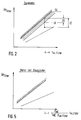
- the upper of the two graphs shown in FIG. 2 shows the limit value for the loading of the particle filter, which is constantly defined by the gradient of the graph.
- This limit value GK can be determined, for example, in test bench tests, the limit value for the loading condition of the particle filter being determined, for example, as a function of the permissible power loss of the diesel engine due to the clogging of the particle filter with soot particles and the like.
- the second, lower graph represents the unloaded state of the particle filter in comparison to the maximum permissible load state represented by the upper graph.
- thermodynamic variables ⁇ p filter and t m, filter and the engine speed n shown in FIG. 2 it is therefore possible to determine whether the operating point of the particle filter defined by the above variables with the permissible loading limit GK maximum permissible loading condition has been reached or how far the current loading condition of the particle filter defined by the operating point is from the permissible loading condition.
- an actual characteristic value IK characterizing the current loading condition that is the operating point of the particle filter
- FIG. 2 there is an actual difference DI at this operating point of the particle filter between the limit characteristic value GK and the actual characteristic value IK.
- the maximum loading condition has therefore not yet been reached in this point. This means that regeneration of the particle filter does not have to be initiated yet. This is only the case when the actual characteristic value IK is equal to the limit characteristic value GK.
- thermodynamic variables .DELTA.p filter and t m, filter ascertained by means of the measuring devices 24, 27, 28 shown in FIG. 1 and the engine speed n proportional to the volume flow are transferred to a computing device 29.
- the computing device 29 first calculates the actual characteristic value as the quotient of the filter differential pressure ⁇ p filter and the product of the engine speed n and the average filter temperature t m, filter .
- the actual difference DI between the calculated actual characteristic value IK and the limit characteristic value GK is then formed and displayed.
- the check is carried out to determine whether the actual difference DI is smaller than a predetermined target difference DS. In the affirmative, the regeneration device is then started, that is to say the combustion chamber 19 shown in FIG. 1 is started.
- FIG. 4 shows a particle filter 10, which in the exhaust system 11 is provided with an exhaust gas charger 30 Diesel engine 12 is arranged.
- the components of the exhaust system 11 shown in FIG. 4 which correspond to the components in FIG. 1 , have the same reference numerals as in FIG. 1 .
- the exhaust gas charger 30 upstream of the diesel engine 12 is provided in FIG .
- the exhaust gas charger 30 essentially consists of a compressor 31 connected into the intake line 21, which is driven by an exhaust gas turbine 32 which is coupled to the compressor 31 and is arranged in the exhaust pipe 17.
- An intercooler 33 can optionally be provided between the compressor 31 of the exhaust gas charger 30 and the inlet to the diesel engine 12 in the intake line 21.
- a pressure measuring device 34 for measuring the pressure in the volume flow at the engine inlet p ME and a temperature measuring device 35 for measuring the temperature t ME of the volume flow 22 entering the diesel engine 12 in the intake line 21, directly upstream of the engine input.
- a pressure measuring device 36 which detects the filter pre-pressure p upstream of the filter is arranged.
- the pressure measuring device 36 can also be formed from the sensor 25 of the differential pressure measuring device 24, so that the pressure measuring device 36 virtually one Forms part of the differential pressure measuring device 24.
- the diagram shown in FIG. 5 shows the determined linear relationship between the filter differential pressure ⁇ p filter and the mean filter temperature t m, filter and the volume flow introduced into the diesel engine. Due to the compression of the volume flow introduced into the diesel engine 12 by the exhaust gas charger 30, the volume flow proportional quantity plotted along the abscissa in FIG. 5 is not solely speed-dependent (as shown in FIG. 2 ), but is also determined by the quotient from the engine inlet pressure p ME and the product of the engine inlet temperature t ME and the filter pre-pressure p pre-filter .
- FIG. 6 shows on the basis of a flow diagram how a method for determining the loading state of a particle filter which is arranged in the exhaust system of a diesel engine provided with an exhaust gas charger can be carried out.
- the measured values acquired by means of the measuring devices shown in FIG. 4 namely the engine speed n, the filter differential pressure ⁇ p filter , the mean filter temperature t m, filters , the engine inlet pressure p ME , the engine inlet temperature t ME and the filter pre-pressure p before filter to the computing device 29 to hand over.
- the computing operation shown in FIG. 6 is carried out to calculate the actual characteristic value IK.
- the further sequence shown in FIG. 6 corresponds to the sequence shown in FIG. 3 after calculation of the actual characteristic value IK, so that reference is made to the description of FIG. 3 for further explanation.
Abstract
Description
Die Erfindung betrifft ein Verfahren zur Ermittlung des Beladungszustands eines im Abgassystem eines, insbesondere in einem Kraftfahrzeug eingesetzten Dieselmotors verwendeten Partikelfilters, sowie eine Vorrichtung zur Durchführung des Verfahrens.The invention relates to a method for determining the loading state of a particle filter used in the exhaust system of a diesel engine, in particular used in a motor vehicle, and a device for carrying out the method.
Die zur Abgasreinigung bei Dieselmotoren zunehmend eingesetzten Partikelfilter, die neben dem Herausfiltern anderer schädlicher Gasbestandteile des Motorabgases insbesondere zum Herausfiltern von im Abgas mitgeführten Rußpartikeln dienen, müssen, um ihre Funktionsfähigkeit zu erhalten, einer häufigen Reinigung (Regeneration) unterzogen werden. Hierbei hat sich insbesondere die thermische Regeneration von Partikelfiltern als effektiv erwiesen, bei der durch Einführung hochtemperierter Heizgase (etwa 600°C bis 900°C) die im Partikelfilter enthaltenen Rußpartikel entzündet und verbrannt werden.The particle filters increasingly used for exhaust gas cleaning in diesel engines, which in addition to filtering out other harmful gas components of the engine exhaust gas, in particular for filtering out soot particles carried in the exhaust gas, must be subjected to frequent cleaning (regeneration) in order to maintain their functionality. In particular, the thermal regeneration of particle filters has proven to be effective, in which the soot particles contained in the particle filter are ignited and burned by introducing high-temperature heating gases (approximately 600 ° C to 900 ° C).
Zur Durchführung der thermischen Regeneration von Partikelfiltern sind im wesentlichen drei Verfahren, nämlich die Standregeneration, die Wechselregeneration und die Vollstromregeneration, bekannt. Bei der Standregeneration erfolgt das Ausbrennen des Partikelfilters bei Stillstand des Kraftfahrzeugmotors mittels einer hierzu vorgesehenen, motorunabhängigen Heizeinrichtung. Die Wechselregeneration ermöglicht eine thermische Regenerierung des Partikelfilters während des Kraftfahrzeugbetriebs. Hierzu sind zwei Partikelfilter parallelgeschaltet, wobei wechselweise ein Partikelfilter vom Motorabgas durchströmt wird, und der andere vom Abgassystem entkoppelte Partikelfilter für die Zeit der thermischen Regenerierung von einem, durch eine motorunabhängige Heizeinrichtung temperierten Heizgas durchströmt wird. Bei der Vollstromregeneration, bei der die Regenerierung ebenso während des Kraftfahrzeugbetriebes erfolgt, wird in den permanent im Abgasstrom befindlichen Partikelfilter für die Zeit der Regenerierung ein durch eine motorunabhängige Heizeinrichtung erzeugter Heizgasstrom mit dem Motorabgas vermischt und zusammen mit diesem in den Partikelfilter eingeleitet, um die genannte, für die Regenerierung erforderliche Gastemperatur zu erreichen.There are essentially three methods known for carrying out the thermal regeneration of particle filters, namely stationary regeneration, alternating regeneration and full-flow regeneration. In the stationary regeneration, the particulate filter is burned out when the motor vehicle engine is at a standstill by means of a motor-independent heating device provided for this purpose. The alternating regeneration enables thermal Regeneration of the particle filter during vehicle operation. For this purpose, two particle filters are connected in parallel, whereby one of the particle filters is alternately flowed through by the engine exhaust gas, and the other particle filter decoupled from the exhaust gas system is flowed through by a heating gas heated by an engine-independent heating device for the time of thermal regeneration. In the case of full-flow regeneration, in which the regeneration also takes place during motor vehicle operation, a heating gas flow generated by an engine-independent heating device is mixed with the engine exhaust gas in the particle filter which is permanently in the exhaust gas flow for the time of regeneration, and is introduced together with the latter into the particle filter in order to achieve the aforementioned to reach the gas temperature required for regeneration.
Unabhängig von der Wahl des durchgeführten Regenerierungsverfahrens ist es natürlich nur dann erforderlich, eine thermische Regeneration durchzuführen, wenn ein bestimmter Beladungszustand des Partikelfilters erreicht ist, bei dem entweder die Wirksamkeit des Filters nicht mehr gegeben ist, oder der durch den zugesetzten Filter entstehende Abgasgegendruck sich nachteilig auf die Motorleistung auswirkt, oder der Filter durch weitere Beladung bei der nächsten Regeneration aufgrund der bei der Rußverbrennung frei werdenden Wärme thermisch zerstört werden würde.Regardless of the choice of the regeneration process carried out, it is of course only necessary to carry out a thermal regeneration if a certain loading state of the particle filter has been reached, in which either the effectiveness of the filter is no longer given, or the exhaust gas back pressure generated by the added filter is disadvantageous affects the engine performance, or the filter would be thermally destroyed by further loading during the next regeneration due to the heat released during soot combustion.
Da bislang praktikable Möglichkeiten, den Beladungszustand eines Partikelfilters während des Betriebs kontinuierlich zu überwachen, nicht bekannt sind, werden von den Herstellern von Partikelfiltern bestimmte, feststehende Betriebsintervalle vorgegeben, in denen eine thermische Regenerierung durchzuführen ist. In Ermangelung der Kenntnis des tatsächlichen Beladungszustands werden die Regenerierungsintervalle so gewählt, daß auch unter extremen Betriebsbedingungen des Motors, etwa häufiger Kurzstreckenbetrieb mit extremer Rußausbildung in den Motorabgasen, eine genügende Sicherheit in den Intervallen vorgesehen ist, damit die Regenerierung in jedem Fall rechtzeitig vor dem Auftreten der beschriebenen schädlichen Auswirkungen erfolgen kann. Somit erfolgt zwangsläufig die Regenerierung eines Partikelfilters bei einem rußarmen Motorbetrieb zu einem Zeitpunkt, wo sie noch gar nicht notwendig wäre.Since hitherto practicable possibilities for continuously monitoring the loading status of a particle filter during operation are not known, the manufacturers of particle filters specify certain, fixed operating intervals in which thermal regeneration takes place is to be carried out. In the absence of knowledge of the actual load condition, the regeneration intervals are chosen so that even under extreme operating conditions of the engine, such as frequent short-distance operation with extreme soot formation in the engine exhaust gases, sufficient safety is provided in the intervals so that the regeneration in any case before the occurrence the described harmful effects can occur. Thus, the regeneration of a particulate filter inevitably takes place when the engine is low in soot at a time when it would not be necessary at all.
Zwar ist man dazu übergegangen, die Regenerierungsintervalle durch Berücksichtigung der überwiegend vorherrschenden Betriebsbedingungen, also etwa Kurzstrecken- oder Langstreckenbetrieb, den besonderen Einsatzbedingungen eines Partikelfilters anzupassen, jedoch erweist sich auch diese verfeinerte Rasterung der Regenerierungsintervalle in der Praxis als zu grob.Although it has become common practice to adapt the regeneration intervals to the particular operating conditions of a particle filter by taking into account the predominantly prevailing operating conditions, e.g. short-haul or long-haul operation, this refined screening of the regeneration intervals has also proven to be too rough in practice.
Der allgemein bekannte Zusammenhang zwischen dem Druckabfall in einem Strömungsmedium bei Durchströmung eines Filters bzw. dem Druckaufbau vor dem Filter und dem Zusetzungsgrad oder der Beladung des Filters, der so ohne weiteres nur für stationär durchströmte Filter gilt, kann man wegen des überwiegend instationären Betriebs eines Verbrennungsmotors nicht allein zur Ermittlung des Beladungszustands eines Partikelfilters heranziehen. Vielmehr ist hierbei der etwa sich in Abhängigkeit von der Motordrehzahl ändernde Volumenstrom durch das Filter zu berücksichtigen.The generally known relationship between the pressure drop in a flow medium when flowing through a filter or the pressure build-up in front of the filter and the degree of clogging or the loading of the filter, which thus applies only to filters with a steady flow, can be seen due to the predominantly unsteady operation of an internal combustion engine not only to determine the loading condition of a particle filter. Rather, the volume flow through the filter, which changes depending on the engine speed, has to be taken into account.
Der Erfindung liegt die Aufgabe zugrunde, ein Verfahren sowie eine Vorrichtung vorzuschlagen, das bzw. die eine einfache Ermittlung des tatsächlich gegebenen Beladungszustands eines Partikelfilters unter Berücksichtigung der gegebenen Motorbetriebsverhältnisse ermöglicht.The invention is based on the object of proposing a method and a device which enables a simple determination of the actually given loading state of a particle filter, taking into account the given engine operating conditions.
Diese Aufgabe wird durch die Merkmale des Anspruchs 1 gelöst.This object is solved by the features of claim 1.
Bei dem erfindungsgemäßen Verfahren wird durch die Messung zumindest einer den Zustand des Abgasvolumenstroms kennzeichnenden filterspezifischen, thermodynamischen Größe und deren Zuordnung zu einer gemessenen motorspezifischen Größe, die volumenstromproportional ist, ein einfacher Zusammenhang zwischen Meßwerten geschaffen, der die Bestimmung eines den Beladungszustand des Partikelfilters kennzeichnenden Ist-Kennwertes ermöglicht. Durch Vergleich mit einem empirisch ermittelten Grenzkennwert ist die Abweichung des Ist-Kennwertes vom Grenzkennwert als Differenz erfaßbar, um bei hinreichend geringer Differenz, deren Größe definitionsgemäß zwischen null und einem beliebigen Wert liegen kann, einen Regenerierungsvorgang einzuleiten.In the method according to the invention, the measurement of at least one filter-specific, thermodynamic variable which characterizes the state of the exhaust gas volume flow and its assignment to a measured engine-specific variable, which is proportional to the volume flow, creates a simple relationship between measured values, which determines the determination of the actual state of charge of the particle filter. Characteristic value enabled. By comparison with an empirically determined limit characteristic value, the deviation of the actual characteristic value from the limit characteristic value can be recorded as a difference in order to initiate a regeneration process if the difference is sufficiently small, the size of which can by definition lie between zero and any value.
Dabei kann der Grenzwert etwa als in Prüfstandsversuchen unter Berücksichtigung von verschiedenen Beladungszuständen und Volumenströmen ermittelter Grenzkennlinienverlauf vorgegeben werden. In der Regel wird der zulässige Grenzwert in Abhängigkeit von der Höhe des zugelassenen Drehmomentenabfalls, der sich infolge des durch den Partikelfilter im Abgassystem verursachten Abgasgegendrucks einstellt, festgelegt.The limit value can be specified, for example, as the limit characteristic curve determined in test bench tests, taking into account different loading conditions and volume flows. As a rule, the permissible limit value is determined as a function of the level of the permitted torque drop, which arises as a result of the exhaust gas back pressure caused by the particle filter in the exhaust system.
Als besonders zuverlässig erweist sich die Ermittlung des Ist-Kennwertes, wenn zwei filterspezifische Größen, nämlich ein Druckwert und ein Temperaturwert, sowie als motorspezifische Größe die Motordrehzahl gemessen werden.The determination of the actual characteristic value proves to be particularly reliable if two filter-specific parameters, namely a pressure value and a temperature value, and the engine speed are measured as an engine-specific parameter.
Als vorteilhaft erweist es sich, wenn als Druckwert des Abgasvolumenstroms der Druck vor dem Partikelfilter, also der Filtervordruck, oder der Druckabfall über den Partikelfilter, also der am Partikelfilter gemessene Differenzdruck, sowie als Temperaturwert des Abgasvolumenstroms die mittlere Volumenstromtemperatur im Partikelfilter herangezogen werden.It proves to be advantageous if the pressure in front of the particle filter, i.e. the filter pre-pressure, or the pressure drop across the particle filter, i.e. the differential pressure measured on the particle filter, and the average volume flow temperature in the particle filter are used as the temperature value of the exhaust gas volume flow.
Ein gemäß Anspruch 4 um die Erfassung und Verarbeitung zusätzlicher Meßwerte erweitertes Verfahren ermöglicht besonders vorteilhaft die Ermittlung des Beladungszustands eines Partikelfilters, der im Abgassystem eines mit einer Abgasaufladung versehenen Dieselmotors angeordnet ist. Hierbei werden neben den filterspezifischen Größen, nämlich dem Druck vor dem Partikelfilter, dem Druckabfall über den Partikelfilter und der Temperatur des Abgasvolumenstroms im Partikelfilter, auch spezifische Größen des Ladevolumenstroms, nämlich die Temperatur und der Druck des Ladevolumenstroms, bei der Bestimmung des Ist-Kennwertes des Beladungszustands berücksichtigt.A method expanded according to claim 4 by the acquisition and processing of additional measured values particularly advantageously enables the determination of the loading state of a particle filter which is arranged in the exhaust system of a diesel engine provided with an exhaust gas charge. In addition to the filter-specific parameters, namely the pressure upstream of the particle filter, the pressure drop across the particle filter and the temperature of the exhaust gas volume flow in the particle filter, specific parameters of the charge volume flow, namely the temperature and pressure of the charge volume flow, are also used to determine the actual characteristic value of the Load condition taken into account.
Vorzugsweise wird bei Feststellung des Vorliegens einer hinreichend geringen Differenz zwischen einem Ist-Kennwert und einem entsprechenden Grenzkennwert eine Anzeigeeinrichtung aktiviert, die, etwa bei Verwendung des erfindungsgemäßen Verfahrens in einem Kraftfahrzeug, den Kraftfahrzeugführer vom kritischen Beladungszustand des Partikelfilters in Kenntnis setzt. Dieser kann dann eine Regeneration des Partikelfilters gemäß einem der vorstehend geschilderten Regenerationsverfahren in Gang setzen.When the existence of a sufficiently small difference between an actual characteristic value and a corresponding limit characteristic value is ascertained, a display device is preferably activated which, for example when the method according to the invention is used in a motor vehicle, by the motor vehicle driver critical loading state of the particle filter. The latter can then initiate regeneration of the particle filter in accordance with one of the regeneration methods described above.
Eine weitere Möglichkeit besteht darin, die Anzeigeeinrichtung mit einer Starteinrichtung zur automatischen Auslösung eines der geschilderten Regenerationsverfahren zu koppeln, oder etwa auch bei Feststellung eines kritischen Differenzwertes unmittelbar die Starteinrichtung auszulösen, ohne vorher den Wert zur Anzeige zu bringen.Another possibility is to couple the display device to a start device for automatically triggering one of the regeneration processes described, or to trigger the start device directly even if a critical difference value is determined, without first displaying the value.
Wenn eine Anzeigeeinrichtung vorgesehen wird, erweist es sich als besonders vorteilhaft, den bei dem erfindungsgemäßen Verfahren ermittelten Ist-Kennwert, ausgehend von einem eine festgelegte Differenz zum Grenzkennwert aufweisenden Anfangskennwert, kontinuierlich oder in vorgegebenen zeitlichen Abständen zur Anzeige zu bringen, um das Fortschreiten des Beladungszustands von außen her sichtbar zu machen, so daß die Notwendigkeit der Durchführung einer Partikelfilterregeneration im voraus erkennbar ist.If a display device is provided, it proves to be particularly advantageous to display the actual characteristic value, ascertained in the method according to the invention, continuously or at predetermined time intervals, based on an initial characteristic value having a defined difference from the limit characteristic value, in order to indicate the progress of the loading state to make it visible from the outside, so that the necessity of performing a particle filter regeneration can be recognized in advance.
Die erfindungsgemäße Vorrichtung zur Ermittlung des Beladungszustands eines im Abgassystem eines, insbesondere in einem Kraftfahrzeug eingesetzten Dieselmotors verwendeten Partikelfilters, weist die Merkmale des Anspruchs 7 auf.The device according to the invention for determining the loading state of a particle filter used in the exhaust system of a diesel engine, in particular used in a motor vehicle, has the features of claim 7.
Die erfindungsgemäße Vorrichtung weist im Bereich des Partikelfilters eine den Druckabfall im Abgasvolumenstrom über den Partikelfilter erfassende Differenzdruckmeßeinrichtung oder eine vor dem Partikelfilter angeordnete, den Filtervordruck messende Druckmeßeinrichtung auf. Ebenfalls im Bereich des Partikelfilters befindet sich eine die Temperatur des Abgasvolumenstroms erfassende Temperaturmeßeinrichtung. Als weitere Meßeinrichtung ist eine Motormeßeinrichtung vorgesehen zur Erfassung einer volumenstromproportionalen, motorspezifischen Größe. Zur Bildung eines Ist-Kennwerts mittels der durch die vorstehend genannten Meßeinrichtungen erfaßten Meßwerte ist eine Recheneinrichtung vorgesehen, die zudem einen Vergleich des derart ermittelten Ist-Kennwertes mit einem vorgegebenen Grenzkennwert ermöglicht. Schließlich kann die erfindungsgemäße Vorrichtung noch eine Anzeigeeinrichtung aufweisen, die dazu dient, das Erreichen des Grenzkennwertes und/oder die durch den Vergleich in der Recheneinrichtung ermittelte Differenz zwischen dem Ist-Kennwert und dem Grenzkennwert anzuzeigen.In the area of the particle filter, the device according to the invention has a differential pressure measuring device which detects the pressure drop in the exhaust gas volume flow via the particle filter or a filter pre-pressure arranged in front of the particle filter measuring pressure measuring device. Also in the area of the particle filter is a temperature measuring device that detects the temperature of the exhaust gas volume flow. A motor measuring device is provided as a further measuring device for detecting a volume-specific, motor-specific variable. In order to form an actual characteristic value by means of the measured values detected by the above-mentioned measuring devices, a computing device is provided which also enables a comparison of the actual characteristic value determined in this way with a predetermined limit characteristic value. Finally, the device according to the invention can also have a display device which serves to indicate when the limit characteristic value has been reached and / or the difference between the actual characteristic value and the limit characteristic value determined by the comparison in the computing device.
Wenn die Anzeigeeinrichtung derart ausgebildet ist, daß sie lediglich das Erreichen des Grenzkennwertes anzeigt, ist für den Kraftfahrzeugführer das Signal gegeben, einen Regenerierungsvorgang beim Partikelfilter vorzunehmen. Bei Anzeige der Differenz zwischen dem Ist-Kennwert und dem Grenzkennwert besteht für den Kraftfahrzeugführer die Möglichkeit, sich ständig über den Fortschritt des Beladungszustands zu informieren und den Zeitpunkt für die Druchführung einer Regenerierung in gewissem Umfang selbst zu bestimmen.If the display device is designed such that it only indicates that the limit characteristic value has been reached, the signal is given to the motor vehicle driver to carry out a regeneration process in the particle filter. When the difference between the actual characteristic value and the limit characteristic value is displayed, the motor vehicle driver has the possibility of constantly being informed about the progress of the loading condition and to a certain extent determining the time for carrying out a regeneration himself.
Die Vorrichtung gemäß Anspruch 9 ist eine Ausführungsvariante der erfindungsgemäßen Vorrichtung, die einen besonders vorteilhaften Einsatz bei der Ermittlung des Beladungszustands eines Partikelfilters ermöglicht, der im Abgassystem eines aufgeladenen Dieselmotors angeordnet ist. Bei dieser Ausführungsvariante sind neben den Meßeinrichtungen zur Messung von filterspezifischen Größen, nämlich einer Differenzdruckmeßeinrichtung, einer den Filtervordruck messenden Druckmeßeinrichtung und einer Temperaturmeßeinrichtung, sowie einer Meßeinrichtung zur Erfassung einer volumenstromproportionalen, motorspezifischen Größe, auch Meßeinrichtungen zur Messung spezifischer Größen des Ladevolumenstroms, nämlich eine die Temperatur des Ladevolumenstroms erfassende Temperaturmeßeinrichtung und eine den Druck des Ladevolumenstroms erfassende Druckmeßeinrichtung, vorgesehen.The device according to claim 9 is an embodiment variant of the device according to the invention, which enables a particularly advantageous use in determining the loading state of a particle filter that is charged in the exhaust system Diesel engine is arranged. In this embodiment variant, in addition to the measuring devices for measuring filter-specific quantities, namely a differential pressure measuring device, a pressure measuring device measuring the filter admission pressure and a temperature measuring device, and a measuring device for detecting a volume-flow-proportional, motor-specific quantity, there are also measuring devices for measuring specific quantities of the loading volume flow, namely a temperature of the loading volume flow temperature measuring device and a pressure measuring device detecting the pressure of the loading volume flow are provided.
Sowohl bei der besonders zur Verwendung bei einem Saug-Dieselmotor geeigneten Vorrichtung gemäß Anspruch 7 als auch bei der besonders zur Verwendung bei einem aufgeladenen Dieselmotor geeigneten Vorrichtung gemäß Anspruch 9 ist es möglich, neben der Anzeigeeinrichtung oder anstatt dieser eine in Abhängigkeit von der Differenz zwischen dem Ist-Kennwert und dem Grenzkennwert betätigbare Starteinrichtung vorzusehen, die ein In-Gang-Setzen einer Regenerierungseinrichtung, insbesondere einer Brennereinrichtung zur thermischen Regeneration, bewirkt.Both in the device particularly suitable for use in a naturally aspirated diesel engine according to claim 7 and in the device particularly suitable for use in a supercharged diesel engine according to claim 9, it is possible, in addition to or instead of the display device, as a function of the difference between the Actual characteristic value and the limit characteristic value actuable starting device to be provided, which causes a regeneration device, in particular a burner device for thermal regeneration, to be started.
Das erfindungsgemäße Verfahren sowie die erfindungsgemäße Vorrichtung zur Ermittlung des Beladungszustands eines Partikelfilters werden nachfolgend anhand der Zeichnungen näher erläutert. Es zeigen:
- Fig. 1
- einen bei einem als Saugmotor ausgebildeten Dieselmotor zwischen Komponenten eines Abgassystems installierten Partikelfilter mit am Motor und im Bereich des Partikelfilters angeordneten Meßeinrichtungen;
- Fig. 2
- ein Diagramm mit Darstellung eines beispielhaften Grenzkennlinienverlaufs für den Beladungszustand eines im Abgassystem eines als Saugmotor ausgebildeten Dieselmotors angeordneten Partikelfilters;
- Fig. 3
- ein Flußdiagramm zur Darstellung der Beladungszustandsermittlung bei einem im Abgassystem eines als Saugmotor ausgebildeten Dieselmotors angeordneten Partikelfilter;
- Fig. 4
- einen bei einem mit einem Abgaslader versehenen Dieselmotor zwischen Komponenten des Abgassystems installierten Partikelfilter mit im Bereich des Motors und im Bereich des Partikelfilters installierten Meßeinrichtungen;
- Fig. 5
- ein Diagramm mit Darstellung eines beispielhaften Grenzkennlinienverlaufs für die Beladung eines im Abgassystem eines mit einem Abgaslader versehenen Dieselmotors angeordneten Partikelfilters;
- Fig. 6
- ein Flußdiagramm zur Darstellung der Beladungszustandsermittlung bei einem im Abgassystem eines mit einem Abgaslader versehenen Dieselmotors angeordneten Partikelfilter.
- Fig. 1
- a particulate filter installed in a diesel engine designed as a naturally aspirated engine between components of an exhaust system with measuring devices arranged on the engine and in the area of the particulate filter;
- Fig. 2
- a diagram showing an exemplary limit characteristic curve for the loading state of a particle filter arranged in the exhaust system of a diesel engine designed as a naturally aspirated engine;
- Fig. 3
- a flowchart showing the determination of the load state in a particulate filter arranged in the exhaust system of a diesel engine designed as a naturally aspirated engine;
- Fig. 4
- a particle filter installed in a diesel engine provided with an exhaust gas charger between components of the exhaust system with measuring devices installed in the area of the engine and in the area of the particle filter;
- Fig. 5
- a diagram showing an exemplary limit characteristic curve for loading a in the exhaust system a particle filter provided with a diesel engine;
- Fig. 6
- a flowchart showing the determination of the load state in a particulate filter arranged in the exhaust system of a diesel engine provided with an exhaust gas charger.
Fig. 1 zeigt einen Partikelfilter 10, der in einem Abgassystem 11 eines als Saugmotor betriebenen Dieselmotors 12 angeordnet ist. Der Partikelfilter 10 ist über Flanschverbindungen 13, 14 auf seiner Eingangsseite mit einer Vorkammer 15 und auf seiner Ausgangsseite mit einem Reduzierstück 16 verbunden. Die Vorkammer 15 ist mit dem Dieselmotor 12 über ein Abgasrohr 17 verbunden. Das Reduzierstück 16 geht strömungsabseitig in ein Abgasrohr 18 über, durch das die Motorabgase in Richtung auf das freie Ende des Abgassystems 11 abgeleitet werden. Ein durch eine Ansaugleitung 21 dem Dieselmotor 12 zugeführter Luftstrom 22 wird in der in Fig. 1 schematisch dargestellten Anlage im Dieselmotor 12 unter Zuführung von Brennstoff verbrannt, und die entstehenden Abgase werden durch das Abgasrohr 17, die Vorkammer 15, den Partikelfilter 10, das Reduzierstück 16 und das anschließende Abgasrohr 18 sowie durch weitere nicht dargestellte Abgassystemkomponenten hindurch als Abgasstrom 23 ins Freie geleitet, nachdem im Partikelfilter 10 die Rußbestandteile und sonstige schädliche Bestandteile im wesentlichen aus dem Abgasstrom herausgefiltert worden sind. 1 shows a
Für die Regeneration des Partikelfilters 10 ist eine Brennkammer 19 vorgesehen, die zur Aufheizung eines in diese durch eine Zuführung 20 eingeleiteten Gasstroms dient. Bei einer Regeneration wird der durch die Zuführung 20 eingeleitete Gasstrom zur Erzielung der für die Regeneration notwendigen Abgastemperatur in der Brennkammer 19 aufgeheizt und mit dem durch das Abgasrohr 17 in die Vorkammer 14 einströmenden Abgasstrom vermischt.A
Um am eingebauten Partikelfilter 10 den Beladungszustand feststellen zu können, sind in der in Fig. 1 dargestellten Anlage verschiedene Meßeinrichtungen vorgesehen. Im Bereich des Partikelfilters 10 ist eine Differenzdruckmeßeinrichtung 24 vorgesehen, die bei dem hier dargestellten Ausführungsbeispiel zwei Meßfühler 25, 26 aufweist. Dabei ist der Meßfühler 25 zur Messung des Drucks im Abgasvolumenstrom vor Eintritt in den Partikelfilter und der Meßfühler 26 zur Messung des Drucks im Abgasvolumenstrom nach Austritt aus dem Partikelfilter 10 vorgesehen. Insgesamt wird durch die Differenzdruckmeßeinrichtung 24 auf bekannte Art und Weise der zwischen den Einbauorten der Meßfühler 25, 26 herrschende Differenzdruck, also der Druckabfall über den Partikelfilter 10, ermittelt. Darüber hinaus dient der dem Partikelfilter 10 vorgeordnete Meßfühler 25 zur Zustandsbeschreibung des Abgases am Filtereintritt.In order to determine the load status on the built
Als weitere Meßeinrichtung im Bereich des Partikelfilters 10 ist eine mit Meßfühlern 37, 38 versehene Temperaturmeßeinrichtung 27 vorgesehen, mittels der die mittlere Temperatur des Abgasvolumenstroms im Partikelfilter 10 bestimmbar ist. Schließlich ist eine an den Dieselmotor 12 angeschlossene Drehzahlmeßeinrichtung 28 vorgesehen.A
Es wurde herausgefunden, daß zwischen dem Quotienten aus dem durch die Differenzdruckmeßeinrichtung 24 ermittelten Filterdifferenzdruck ΔpFilter und der mittels der Temperaturmeßeinrichtung 27 ermittelten mittleren Filtertemperatur tm sowie der über die Drehzahlmeßeinrichtung 28 ermittelten volumenstromproportionalen Drehzahl des Dieselmotors 12 die in Fig. 2 dargestellte Beziehung herrscht. Der obere der beiden in Fig. 2 dargestellten Graphen gibt den Grenzkennwert für die Beladung des Partikelfilters wieder, der durch den Gradienten des Graphen konstant definiert ist. Dieser Grenzkennwert GK kann etwa in Prüfstandsversuchen ermittelt werden, wobei der Grenzkennwert für den Beladungszustand des Partikelfilters etwa in Abhängigkeit vom zulässigen Leistungsverlust des Dieselmotors infolge der Zusetzung des Partikelfiltern mit Rußpartikeln und ähnlichem festgelegt wird.It was found that between the quotient of the filter differential pressure Δp filter determined by the differential
Der zweite, untere Graph stellt im Vergleich zu dem durch den oberen Graphen wiedergegebenen maximal zulässigen Beladungszustand den unbeladenen Zustand des Partikelfilters dar.The second, lower graph represents the unloaded state of the particle filter in comparison to the maximum permissible load state represented by the upper graph.
Aufgrund des in Fig. 2 dargestellten, herausgefundenen Zusammenhangs zwischen den thermodynamischen Größen ΔpFilter und tm,Filter und der Motordrehzahl n ist es daher möglich, durch Vergleich eines durch die genannten Größen definierten Betriebspunktes des Partikelfilters mit der zulässigen Beladungsgrenze GK festzustellen, ob der maximal zulässige Beladungszustand erreicht ist bzw. wie weit der durch den Betriebspunkt definierte aktuelle Beladungszustand des Partikelfilters vom zulässigen Beladungszustand entfernt ist.On the basis of the relationship between the thermodynamic variables Δp filter and t m, filter and the engine speed n shown in FIG. 2 , it is therefore possible to determine whether the operating point of the particle filter defined by the above variables with the permissible loading limit GK maximum permissible loading condition has been reached or how far the current loading condition of the particle filter defined by the operating point is from the permissible loading condition.
Der in Fig. 2 und später nachfolgend in Fig. 5 dargestellte Zusammenhang mit dem Filterdifferenzdruck ΔpFilter als Beladungsindikator gilt ebenso, wenn anstatt des Filterdifferenzdrucks ΔpFilter der Absolutdruck oder der Relativdruck vor dem Filter als Beladungsindikator verwendet werden.The relationship shown in FIG. 2 and later in FIG. 5 with the filter differential pressure Δp filter as a loading indicator also applies if, instead of the filter differential pressure Δp filter, the absolute pressure or the relative pressure upstream of the filter is used as the loading indicator.
Beispielhaft ist in Fig. 2 ein den aktuellen Beladungszustand, also den Betriebspunkt des Partikelfilters, kennzeichnender Ist-Kennwert IK eingetragen. Wie in Fig. 2 weiter dargestellt, besteht in diesem Betriebspunkt des Partikelfilters zwischen dem Grenzkennwert GK und dem Ist-Kennwert IK eine Ist-Differenz DI. Der maximale Beladungszustand ist daher in diesem Punkt auf jeden Fall noch nicht erreicht. Das bedeutet, daß eine Regenierung des Partikelfilters noch nicht eingeleitet werden muß. Dies ist erst dann der Fall, wenn der Ist-Kennwert IK gleich dem Grenzkennwert GK ist. Da es sich in manchen Fällen auch als vorteilhaft erweisen kann, den Regenerierungsvorgang bereits vor Erreichen des durch den Grenzkennwert GK maximal zulässigen Beladungszustands einzuleiten oder zumindest vor dem Eintreten des maximalen Beladungszustands Kenntnis von dem in Kürze zu erwartenden Eintreten des maximalen Beladungszustands zu erhalten, erweist es sich, insbesondere bei einer Darstellung des aktuellen Beladungszustands auf einer Anzeigeeinrichtung als vorteilhaft, eine (in Fig. 2 kreuzschraffiert dargestellte) Toleranzzone über eine Soll-Differenz DS zwischen dem Grenzkennwert GK und dem Ist-Kennwert IK zu definieren. Hierbei kann dann für den Fall, daß DI gleich DS ist, die Regenerierung des Partikelfilters eingeleitet werden bzw. die Notwendigkeit einer demnächst durchzuführenden Regenerierung des Partikelfilters angezeigt werden.As an example, an actual characteristic value IK characterizing the current loading condition, that is the operating point of the particle filter, is entered in FIG . As further shown in FIG. 2 , there is an actual difference DI at this operating point of the particle filter between the limit characteristic value GK and the actual characteristic value IK. The maximum loading condition has therefore not yet been reached in this point. This means that regeneration of the particle filter does not have to be initiated yet. This is only the case when the actual characteristic value IK is equal to the limit characteristic value GK. Since it can prove to be advantageous in some cases to initiate the regeneration process before the maximum load state permitted by the limit characteristic value GK has been reached, or at least before the maximum load state has occurred, it is evident that the maximum load state can be expected shortly It is advantageous, particularly when the current loading state is shown on a display device, to define a tolerance zone (shown cross-hatched in FIG. 2 ) via a target difference DS between the limit characteristic value GK and the actual characteristic value IK. In this case, in the event that DI is DS, the regeneration of the particle filter can be initiated or the need for a regeneration of the particle filter to be carried out soon can be indicated.
Fig. 3 zeigt anhand eines Flußdiagramms, wie das Verfahren zur Ermittlung des Beladungszustands eines im Abgassystem eines als Saugmotor betriebenen Dieselmotors angeordneten Partikelfilters ablaufen kann. Die mittels der in Fig. 1 dargestellten Meßeinrichtungen 24, 27, 28 erfaßten thermodynamischen Größen ΔpFilter und tm,Filter sowie die volumenstromproportionale Motordrehzahl n werden an eine Recheneinrichtung 29 übergeben. In der Recheneinrichtung 29 findet zunächst die Berechnung des Ist-Kennwertes als Quotient aus dem Filterdifferenzdruck ΔpFilter und dem Produkt aus der Motordrehzahl n und der mittleren Filtertemperatur tm,Filter statt. Anschließend wird die Ist-Differenz DI zwischen dem berechneten Ist-Kennwert IK und dem Grenzkennwert GK gebildet und zur Anzeige gebracht. 3 shows on the basis of a flow diagram how the method for determining the loading state of a particle filter arranged in the exhaust system of a diesel engine operated as a naturally aspirated engine can run. The thermodynamic variables .DELTA.p filter and t m, filter ascertained by means of the measuring
Gemäß der Darstellung in Fig. 3 erfolgt nach Berechnung der Ist-Differenz DI die Überprüfung, ob die Ist-Differenz DI kleiner ist als eine vorgegebene Soll-Differenz DS. Bejahendenfalls erfolgt hieran anschließend das In-Gang-Setzen der Regenerationseinrichtung, also etwa das In-Gang-Setzen der in Fig. 1 dargestellten Brennkammer 19. 3 , after calculating the actual difference DI, the check is carried out to determine whether the actual difference DI is smaller than a predetermined target difference DS. In the affirmative, the regeneration device is then started, that is to say the
Natürlich ist es auch möglich, den Vergleich nicht erst nach Berechnung der Ist-Differenz DI durchzuführen, sondern den Ist-Kennwert IK unmittelbar mit dem Grenzkennwert GK zu vergleichen und bei Feststellung eines Übereinstimmens der Kennwerte bzw. des Überschreitens des Grenzkennwertes GK den Regenerationsvorgang einzuleiten.Of course, it is also possible not to carry out the comparison only after calculating the actual difference DI, but to compare the actual characteristic value IK directly with the limit characteristic value GK and to initiate the regeneration process if the characteristic values match or if the limit characteristic value GK is exceeded.
Fig. 4 zeigt einen Partikelfilter 10, der im Abgassystem 11 eines mit einem Abgaslader 30 versehenen Dieselmotors 12 angeordnet ist. Die in Fig. 4 dargestellten, mit den Komponenten in Fig. 1 übereinstimmenden Komponenten des Abgassystems 11 weisen mit Fig. 1 übereinstimmende Bezugszeichen auf. Im Unterschied zu der in Fig. 1 dargestellten Anlage ist in Fig. 4 der dem Dieselmotor 12 vorgeschaltete Abgaslader 30 vorgesehen. Der Abgaslader 30 besteht im wesentlichen aus einem in die Ansaugleitung 21 geschalteten Verdichter 31, der über eine, an den Verdichter 31 angekoppelte Abgasturbine 32, die im Abgasrohr 17 angeordnet ist, angetrieben wird. Optional kann zwischen dem Verdichter 31 des Abgasladers 30 und dem Eingang zum Dieselmotor 12 in der Ansaugleitung 21 ein Zwischenkühler 33 vorgesehen werden. FIG. 4 shows a
Neben den bereits in der Anlage gemäß Fig. 1 vorgesehenen Meßeinrichtungen, nämlich der Differenzdruckmeßeinrichtung 24, der Drehzahlmeßeinrichtung 28 und der Temperaturmeßeinrichtung 27 sind in der in Fig. 4 dargestellten Anlage weitere Meßeinrichtungen vorgesehen. Zum einen befinden sich in der Ansaugleitung 21, dem Motoreingang unmittelbar vorgeordnet, eine Druckmeßeinrichtung 34 zur Messung des Drucks im Volumenstrom am Motoreingang pME und eine Temperaturmeßeinrichtung 35 zur Messung der Temperatur tME des in den Dieselmotor 12 eintretenden Volumenstroms 22. Bei einer vereinfachten Ausführungsform kann auf die Temperaturmeßeinrichtung 35 auch verzichtet werden. Darüber hinaus ist im Eintrittsbereich des Abgasvolumenstroms in den Partikelfilter 10, hier in der Vorkammer 15, eine den Filtervordruck pvorFilter erfassende Druckmeßeinrichtung 36 angeordnet. Natürlich kann die Druckmeßeinrichtung 36 auch aus dem Meßfühler 25 der Differenzdruckmeßeinrichtung 24 gebildet sein, so daß die Druckmeßeinrichtung 36 quasi einen Bestandteil der Differenzdruckmeßeinrichtung 24 bildet.In addition to the measuring devices already provided in the system according to FIG. 1 , namely the differential
Das in Fig. 5 dargestellte Diagramm zeigt den festgestellten linearen Zusammenhang zwischen dem Filterdifferenzdruck ΔpFilter und der mittleren Filtertemperatur tm,Filter sowie dem in den Dieselmotor eingeleiteten Volumenstrom. Aufgrund der durch den Abgaslader 30 erfolgten Verdichtung des in den Dieselmotor 12 eingeleiteten Volumenstroms ist die in Fig. 5 längs der Abszisse aufgetragene volumenstromproportionale Größe nicht allein (wie in Fig. 2 dargestellt) drehzahlabhängig, sondern wird auch bestimmt durch den Quotienten aus dem Motoreintrittsdruck pME und dem Produkt aus der Motoreintrittstemperatur tME und dem Filtervordruck pvorFilter.The diagram shown in FIG. 5 shows the determined linear relationship between the filter differential pressure Δp filter and the mean filter temperature t m, filter and the volume flow introduced into the diesel engine. Due to the compression of the volume flow introduced into the
Ansonsten gelten in Fig. 5 ebenso die in Fig. 2 dargestellten Zusammenhänge betreffend den Grenzkennwert GK, den Ist-Kennwert IK, die Soll-Differenz DS und die Ist-Differenz DI.Otherwise, the relationships shown in FIG. 2 also apply in FIG. 5 regarding the limit characteristic value GK, the actual characteristic value IK, the target difference DS and the actual difference DI.
Fig. 6 zeigt anhand eines Flußdiagramms, wie ein Verfahren zur Ermittlung des Beladungszustands eines Partikelfilters, der im Abgassystem eines mit einem Abgaslader versehenen Dieselmotors angeordnet ist, ablaufen kann. Zunächst werden die mittels der in Fig. 4 dargestellten Meßeinrichtungen erfaßten Meßwerte, nämlich die Motordrehzahl n, der Filterdifferenzdruck ΔpFilter, die mittlere Filtertemperatur tm,Filter, der Motoreintrittsdruck pME, die Motoreintrittstemperatur tME und der Filtervordruck pvorFilter an die Recheneinrichtung 29 übergeben. Daran anschließend wird zur Berechnung des Ist-Kennwertes IK die in Fig. 6 dargestellte Rechenoperation durchgeführt. 6 shows on the basis of a flow diagram how a method for determining the loading state of a particle filter which is arranged in the exhaust system of a diesel engine provided with an exhaust gas charger can be carried out. First, the measured values acquired by means of the measuring devices shown in FIG. 4 , namely the engine speed n, the filter differential pressure Δp filter , the mean filter temperature t m, filters , the engine inlet pressure p ME , the engine inlet temperature t ME and the filter pre-pressure p before filter to the
Der weitere, in Fig. 6 dargestellte Ablauf entspricht dem in Fig. 3 nach Berechnung des Ist-Kennwertes IK dargestellten Ablauf, so daß zur weiteren Erläuterung auf die Beschreibung von Fig. 3 verwiesen wird.The further sequence shown in FIG. 6 corresponds to the sequence shown in FIG. 3 after calculation of the actual characteristic value IK, so that reference is made to the description of FIG. 3 for further explanation.
Claims (10)
dadurch gekennzeichnet, daß
characterized in that
dadurch gekennzeichnet,
daß als filterspezifische Größen ein Druckwert und ein Temperaturwert des Abgasvolumenstroms durch den Partikelfilter (10) und als motorspezifische Größe die Motordrehzahl (n) gemessen werden.Method according to claim 1,
characterized,
that a pressure value and a temperature value of the exhaust gas volume flow through the particle filter (10) are measured as filter-specific variables and the engine speed (n) are measured as engine-specific variables.
dadurch gekennzeichnet,
daß als filterspezifische Größen der Druck vor dem Partikelfilter (Filtervordruck pvorFilter) oder der Druckabfall über den Partikelfilter (10) (Filterdifferenzdruck ΔpFilter) sowie die mittlere Volumenstromtemperatur im Partikelfilter (tm,Filter) gemessen werden.Method according to claim 2,
characterized,
that the filter-specific variables are the pressure upstream of the particle filter (filter pre-pressure p upstream of the filter ) or the pressure drop across the particle filter (10) (filter differential pressure Δp filter ) and the mean volume flow temperature be measured in the particle filter (t m, filter ).
dadurch gekennzeichnet,
daß bei einem mit einem Abgaslader (30) versehenen Dieselmotor (12) darüber hinaus ein Druckwert und ein Temperaturwert des Ladevolumenstroms (pME,tME), sowie neben dem Filterdifferenzdruck (ΔpFilter) der Filtervordruck (pvorFilter) gemessen werden, und unter zusätzlicher Berücksichtigung dieser Meßwerte der Ist-Kennwert (IK) errechnet wird.Method according to claim 2 or 3,
characterized,
that in a diesel engine (12) provided with an exhaust gas charger (30), a pressure value and a temperature value of the charge volume flow (p ME , t ME ), and in addition to the filter differential pressure (Δp filter ), the filter pre-pressure (p pre-filter ) are measured, and below additionally taking these measured values into account, the actual characteristic value (IK) is calculated.
dadurch gekennzeichnet,
daß bei hinreichend geringer Differenz zwischen dem Ist-Kennwert (IK) und dem Grenzkennwert (GK) eine Anzeigeeinrichtung und/oder eine Starteinrichtung zum In-Gang-Setzen des Regenerierungsvorgangs betätigt wird.Method according to one of claims 1 to 4,
characterized,
that if there is a sufficiently small difference between the actual characteristic value (IK) and the limit characteristic value (GK), a display device and / or a starting device is actuated to start the regeneration process.
dadurch gekennzeichnet,
daß die Anzeigeeinrichtung, ausgehend von einem eine festgelegte Differenz zum Grenzkennwert (GK) aufweisenden Anfangskennwert zur Anzeige des Beladungsfortschritts bis zum Erreichen des Grenzkennwerts (GK) verwendet wird.Method according to claim 5,
characterized,
that the display device is used, starting from an initial characteristic value which has a fixed difference to the limit characteristic value (GK), to display the loading progress until the limit characteristic value (GK) is reached.
gekennzeichnet durch
marked by
gekennzeichnet durch
eine Anzeigeeinrichtung zum Anzeigen des Erreichens des Grenzkennwertes (GK) und/oder der Differenz des Ist-Kennwertes (IK) zum Grenzkennwert (GK).Device according to claim 7,
marked by
a display device for displaying the reaching of the limit characteristic value (GK) and / or the difference of the actual characteristic value (IK) to the limit characteristic value (GK).
dadurch gekennzeichnet,
daß bei einem mit einem Abgaslader (30) versehenen Dieselmotor (12) darüber hinaus vorgesehen sind
characterized,
that in a provided with an exhaust gas charger (30) Diesel engine (12) are also provided
dadurch gekennzeichnet,
daß neben der Anzeigeeinrichtung oder anstatt dieser eine in Abhängigkeit von der Differenz zwischen dem Ist-Kennwert (IK) und dem Grenzkennwert (GK) betätigbare Starteinrichtung zum In-Gang-Setzen einer Regenerierungseinrichtung, insbesondere einer Brennereinrichtung (19) zur thermischen Regeneration, vorgesehen ist.Device according to one of claims 7-9,
characterized,
that in addition to the display device or instead of this a starting device which can be actuated as a function of the difference between the actual characteristic value (IK) and the limit characteristic value (GK) is provided for starting a regeneration device, in particular a burner device (19) for thermal regeneration .
Applications Claiming Priority (2)
| Application Number | Priority Date | Filing Date | Title |
|---|---|---|---|
| DE4230180 | 1992-09-09 | ||
| DE4230180A DE4230180A1 (en) | 1992-09-09 | 1992-09-09 | Method and device for determining the loading status of particle filters |
Publications (3)
| Publication Number | Publication Date |
|---|---|
| EP0587146A2 true EP0587146A2 (en) | 1994-03-16 |
| EP0587146A3 EP0587146A3 (en) | 1994-08-24 |
| EP0587146B1 EP0587146B1 (en) | 1997-03-05 |
Family
ID=6467616
Family Applications (1)
| Application Number | Title | Priority Date | Filing Date |
|---|---|---|---|
| EP93114429A Expired - Lifetime EP0587146B1 (en) | 1992-09-09 | 1993-09-08 | Device for determination of the loading state of particle filters |
Country Status (5)
| Country | Link |
|---|---|
| US (1) | US5511413A (en) |
| EP (1) | EP0587146B1 (en) |
| JP (1) | JPH0791227A (en) |
| AT (1) | ATE149634T1 (en) |
| DE (2) | DE4230180A1 (en) |
Cited By (5)
| Publication number | Priority date | Publication date | Assignee | Title |
|---|---|---|---|---|
| WO1999028010A1 (en) * | 1997-12-04 | 1999-06-10 | Elkem Asa | Method for regulating of reverse-air pressure in bag filters |
| FR2781251A1 (en) | 1998-07-20 | 2000-01-21 | Renault | METHOD AND DEVICE FOR DETERMINING THE LOAD OF A PARTICLE FILTER |
| EP1281843A2 (en) * | 2001-08-01 | 2003-02-05 | Renault s.a.s. | Method to determine the loading state of a particulate filter |
| DE10260784A1 (en) * | 2002-12-23 | 2004-07-01 | Daimlerchrysler Ag | Method for monitoring the degree of contamination of a filter device |
| WO2008059166A1 (en) | 2006-11-17 | 2008-05-22 | Saint-Gobain Centre De Recherches Et D'etudes Europeen | Method for the calibration and management of an exhaust line comprising a particle filter |
Families Citing this family (57)
| Publication number | Priority date | Publication date | Assignee | Title |
|---|---|---|---|---|
| DE4416541A1 (en) * | 1994-05-10 | 1995-11-16 | Brueckner Trockentechnik Gmbh | Method and device for cleaning a circulating air stream |
| US5606311A (en) * | 1995-08-30 | 1997-02-25 | General Motors Corporation | Air filter diagnostic |
| US5670714A (en) * | 1996-03-27 | 1997-09-23 | Sorensen; Jens O. | Air-pollution reduction method and system for the interior of an automobile |
| DE19720577A1 (en) * | 1997-05-16 | 1998-11-19 | Bernd Grunwald | Differential measuring unit for determining pressure difference between inlet and outlet side of filter |
| DE19740327A1 (en) * | 1997-09-13 | 1999-03-18 | Univ Karlsruhe | Modular cross-flow filter for preparation of aqueous samples for analysis |
| AT2410U1 (en) * | 1997-09-16 | 1998-10-27 | Avl List Gmbh | METHOD FOR REGENERATING A PARTICLE FILTER |
| JP2002544423A (en) * | 1999-05-07 | 2002-12-24 | ローベルト ボツシユ ゲゼルシヤフト ミツト ベシユレンクテル ハフツング | Method and apparatus for controlling an internal combustion engine with an exhaust gas aftertreatment system |
| US6377171B1 (en) | 1999-09-15 | 2002-04-23 | Peerless Mfg. Co. | On-line filter monitoring system |
| DE19949502A1 (en) | 1999-10-14 | 2001-04-19 | Volkswagen Ag | Method for determining the loading value of a particle filter in internal combustion engines, especially diesel engines |
| DE19951962A1 (en) * | 1999-10-28 | 2001-05-03 | Festo Ag & Co | Filter device for filtering compressed air |
| DE10062022B4 (en) * | 1999-12-14 | 2014-11-20 | Toyota Jidosha Kabushiki Kaisha | Device for detecting a fault in an exhaust system of an engine |
| US6408686B1 (en) * | 2000-01-07 | 2002-06-25 | Ford Global Technologies, Inc. | Exhaust system monitor |
| DE10017361A1 (en) * | 2000-04-07 | 2001-10-11 | Mann & Hummel Filter | Differential pressure measuring arrangement |
| US6397587B1 (en) * | 2000-08-25 | 2002-06-04 | Frod Global Tech., Inc. | System and method for monitoring the loading of a diesel particulate filter |
| GB2397134B (en) * | 2000-08-25 | 2004-12-29 | Ford Global Tech Llc | Monitoring of a diesel particulate filter |
| FR2814498B1 (en) * | 2000-09-27 | 2003-04-11 | Renault | METHOD FOR MANAGING THE OPERATION OF A PARTICLE FILTER FOR A COMBUSTION ENGINE |
| FR2817286B1 (en) * | 2000-11-24 | 2003-01-24 | Renault | PROCESS FOR REGENERATING A PARTICLE FILTER |
| DE10059683B4 (en) * | 2000-12-01 | 2007-10-04 | Audi Ag | Method for monitoring a particulate filter system in the exhaust system of an internal combustion engine |
| FR2832758B1 (en) * | 2001-11-29 | 2004-01-30 | Renault | METHOD AND DEVICE FOR DIAGNOSING THE OPERATING STATE OF AN EXHAUST LINE OF AN INTERNAL COMBUSTION ENGINE |
| ITTO20020072A1 (en) * | 2002-01-25 | 2003-07-25 | Fiat Ricerche | METHOD FOR DETERMINING THE QUANTITY OF PARTICULATE ACCUMULATED IN A FILTER BY PARTICULATE. |
| FR2836956B1 (en) * | 2002-03-08 | 2004-09-17 | Renault | PARTICULATE FILTER REGENERATION PROCESS FOR MOTOR VEHICLES |
| US6651638B1 (en) | 2002-06-28 | 2003-11-25 | Cummins Engine Company, Inc. | System and method for derating an engine to encourage servicing of a vehicle |
| US6948486B2 (en) * | 2002-06-28 | 2005-09-27 | Fleetguard, Inc. | System and method for derating an engine to encourage servicing of a vehicle |
| DE10248431A1 (en) * | 2002-10-17 | 2004-04-29 | Robert Bosch Gmbh | Method for recognizing the loading of a particle filter |
| JP4140371B2 (en) * | 2002-12-16 | 2008-08-27 | 日産自動車株式会社 | Particulate filter regeneration device and engine exhaust gas purification device |
| JP2004197657A (en) * | 2002-12-18 | 2004-07-15 | Nissan Motor Co Ltd | Reproducing apparatus for particulate filter and engine waste gas purifying facility |
| DE10301035A1 (en) * | 2003-01-13 | 2004-07-22 | Hjs Fahrzeugtechnik Gmbh & Co. | Method for regulating the control of a heating device for regenerating a particle filter that is switched on in the exhaust line of an internal combustion engine |
| JP3750664B2 (en) * | 2003-03-07 | 2006-03-01 | 日産自動車株式会社 | Engine exhaust purification system |
| US6871489B2 (en) * | 2003-04-16 | 2005-03-29 | Arvin Technologies, Inc. | Thermal management of exhaust systems |
| US6978604B2 (en) * | 2003-11-06 | 2005-12-27 | International Engine Intellectual Property Company, Llc | Soot burn-off control strategy for a catalyzed diesel particulate filter |
| US6993414B2 (en) * | 2003-12-18 | 2006-01-31 | Carrier Corporation | Detection of clogged filter in an HVAC system |
| JP4038187B2 (en) * | 2004-03-11 | 2008-01-23 | トヨタ自動車株式会社 | Particulate matter regeneration control device for internal combustion engine exhaust purification device |
| DE102004025436A1 (en) * | 2004-05-24 | 2005-12-29 | Umicore Ag & Co. Kg | Virtual load sensor |
| JP4470593B2 (en) * | 2004-06-03 | 2010-06-02 | 株式会社デンソー | Exhaust gas purification device for internal combustion engine |
| FR2872213B1 (en) * | 2004-06-23 | 2006-11-03 | Peugeot Citroen Automobiles Sa | EMERGENCY MEANS REGENERATION SYSTEM FOR MOTOR VEHICLE ENGINE |
| FR2872214B1 (en) | 2004-06-23 | 2006-11-03 | Peugeot Citroen Automobiles Sa | SYSTEM FOR MONITORING THE REGENERATION OF MEANS OF DEPOLLUTION |
| FR2872212B1 (en) * | 2004-06-23 | 2006-11-03 | Peugeot Citroen Automobiles Sa | SYSTEM FOR EVALUATING THE STATE OF CHARGE OF DEPOLLUTION MEANS OF AN EXHAUST LINE |
| US7445705B2 (en) * | 2004-08-19 | 2008-11-04 | Ford Motor Company | Particle filter for fuel cell coolant |
| US20060254260A1 (en) * | 2005-05-16 | 2006-11-16 | Arvinmeritor Emissions Technologies Gmbh | Method and apparatus for piezoelectric injection of agent into exhaust gas for use with emission abatement device |
| US7332142B2 (en) * | 2005-06-17 | 2008-02-19 | Emcon Tehnologies Germany (Augsburg) Gmbh | Method and apparatus for bubble injection of agent into exhaust gas for use with emission abatement device |
| US7406822B2 (en) * | 2005-06-30 | 2008-08-05 | Caterpillar Inc. | Particulate trap regeneration system and control strategy |
| US8209962B2 (en) * | 2005-09-28 | 2012-07-03 | Detroit Diesel Corporation | Diesel particulate filter soot permeability virtual sensors |
| DE102006000845A1 (en) * | 2006-01-05 | 2007-07-12 | Volkswagen Ag | Method for determining the soot load of a particulate filter |
| DE102007003153B4 (en) * | 2007-01-22 | 2011-01-05 | Continental Automotive Gmbh | Method for checking the plausibility of a determined differential pressure value via a particle filter |
| US8011180B2 (en) * | 2007-08-16 | 2011-09-06 | Ford Global Technologies, Llc | Particulate filter regeneration |
| DE102007057039A1 (en) | 2007-11-27 | 2009-05-28 | Robert Bosch Gmbh | Method for detecting the loading of a particulate filter |
| FR2927659B1 (en) * | 2008-02-14 | 2013-02-01 | Renault Sas | ESTIMATING CHARGING OF A PARTICLE FILTER |
| US8146351B2 (en) * | 2009-06-05 | 2012-04-03 | GM Global Technology Operations LLC | Regeneration systems and methods for particulate filters using virtual brick temperature sensors |
| DE102009060509A1 (en) | 2009-12-23 | 2011-06-30 | MTU Friedrichshafen GmbH, 88045 | Process for the regeneration of a particulate filter |
| US20130204508A1 (en) * | 2012-02-08 | 2013-08-08 | GM Global Technology Operations LLC | System and method for controlling an engine |
| DE102015211151B4 (en) * | 2015-06-17 | 2021-08-12 | Vitesco Technologies GmbH | Method and device for determining the loading state of an exhaust gas particle filter |
| DE102015221495A1 (en) | 2015-11-03 | 2017-05-04 | Volkswagen Aktiengesellschaft | Method and apparatus for regeneration of a particulate filter |
| DE102017104469A1 (en) * | 2017-03-03 | 2018-09-06 | Volkswagen Aktiengesellschaft | Method for determining the loading state of a particulate filter and internal combustion engine |
| FR3070728B1 (en) * | 2017-09-06 | 2019-08-30 | Psa Automobiles Sa | METHOD FOR PROTECTING A PARTICLE FILTER IN AN EXHAUST LINE DURING REGENERATION |
| CN109538333B (en) * | 2018-09-17 | 2021-09-14 | 广东工业大学 | Method for judging regeneration time of diesel engine exhaust particle catcher |
| CN113606025B (en) * | 2021-08-20 | 2022-11-22 | 一汽解放汽车有限公司 | Fault diagnosis method for diesel engine DPF trapping efficiency |
| AT525634B1 (en) * | 2022-07-11 | 2023-06-15 | Aigner Gmbh | Process for changing the volume flow of a gaseous fluid |
Citations (4)
| Publication number | Priority date | Publication date | Assignee | Title |
|---|---|---|---|---|
| EP0220484A2 (en) * | 1985-10-26 | 1987-05-06 | MAN Technologie Aktiengesellschaft | Diesel engine with a soot filter |
| EP0260031A1 (en) * | 1986-08-28 | 1988-03-16 | AlliedSignal Inc. | Particulate trap regeneration system for an engine |
| EP0411445A2 (en) * | 1989-08-02 | 1991-02-06 | Cummins Engine Company, Inc. | Regeneratable particulate filter trap system |
| EP0446400A1 (en) * | 1988-09-27 | 1991-09-18 | Konstantin N. Prof.Dr.-Ing. Pattas | Method of and apparatus for the regeneration of a soot filter |
Family Cites Families (15)
| Publication number | Priority date | Publication date | Assignee | Title |
|---|---|---|---|---|
| US3817099A (en) * | 1972-08-09 | 1974-06-18 | Gen Motors Corp | Mass flow air meter |
| DE3219947A1 (en) * | 1982-05-27 | 1983-12-01 | Bayerische Motoren Werke AG, 8000 München | Method for the regeneration of a particulate filter of internal combustion engines |
| JPS59155522A (en) * | 1983-02-23 | 1984-09-04 | Nissan Motor Co Ltd | Control device of burner for regenerating exhaust particulate collecting trap in internal-combustion engine |
| DE3420199A1 (en) * | 1984-05-30 | 1985-12-05 | Knecht Filterwerke Gmbh, 7000 Stuttgart | Method for controlling the combustion of the soot contained in the exhaust gas from internal combustion engines |
| JPS6237934U (en) * | 1985-08-27 | 1987-03-06 | ||
| DE3619397A1 (en) * | 1986-06-09 | 1987-12-10 | Pierburg Gmbh | Method for the regeneration of a soot filter and diesel engine with soot burn-off filter |
| JPH063007B2 (en) * | 1987-07-13 | 1994-01-12 | 山水産業株式会社 | Joint seal members for revetment structures |
| JPS6451888A (en) * | 1987-08-24 | 1989-02-28 | Sharp Kk | Picture processor |
| DE3728713A1 (en) * | 1987-08-28 | 1989-03-09 | Webasto Ag Fahrzeugtechnik | METHOD AND DEVICE FOR OPERATING AN EXHAUST GAS BURNER |
| JPS6477717A (en) * | 1987-09-17 | 1989-03-23 | Matsushita Electric Ind Co Ltd | Exhaust gas purifying device for diesel engine |
| JPH0610409B2 (en) * | 1987-10-19 | 1994-02-09 | 新キャタピラー三菱株式会社 | Engine smoke reduction device |
| US4986069A (en) * | 1989-08-29 | 1991-01-22 | Donaldson Company, Inc. | Engine exhaust particle trap captured mass sensor |
| GB2239407B (en) * | 1989-12-27 | 1994-10-12 | Nissan Motor | Exhaust gas purifying device for an internal combustion engine |
| US5211009A (en) * | 1990-12-17 | 1993-05-18 | Kloeckner-Humboldt-Deutz Ag | Method for the regeneration of particulate-filter systems |
| DE4107388C2 (en) * | 1990-12-17 | 1998-07-02 | Deutz Ag | Process for the regeneration of particle filter systems |
-
1992
- 1992-09-09 DE DE4230180A patent/DE4230180A1/en not_active Withdrawn
-
1993
- 1993-09-08 DE DE59305582T patent/DE59305582D1/en not_active Expired - Fee Related
- 1993-09-08 EP EP93114429A patent/EP0587146B1/en not_active Expired - Lifetime
- 1993-09-08 US US08/118,021 patent/US5511413A/en not_active Expired - Fee Related
- 1993-09-08 AT AT93114429T patent/ATE149634T1/en not_active IP Right Cessation
- 1993-09-09 JP JP5248634A patent/JPH0791227A/en active Pending
Patent Citations (4)
| Publication number | Priority date | Publication date | Assignee | Title |
|---|---|---|---|---|
| EP0220484A2 (en) * | 1985-10-26 | 1987-05-06 | MAN Technologie Aktiengesellschaft | Diesel engine with a soot filter |
| EP0260031A1 (en) * | 1986-08-28 | 1988-03-16 | AlliedSignal Inc. | Particulate trap regeneration system for an engine |
| EP0446400A1 (en) * | 1988-09-27 | 1991-09-18 | Konstantin N. Prof.Dr.-Ing. Pattas | Method of and apparatus for the regeneration of a soot filter |
| EP0411445A2 (en) * | 1989-08-02 | 1991-02-06 | Cummins Engine Company, Inc. | Regeneratable particulate filter trap system |
Cited By (8)
| Publication number | Priority date | Publication date | Assignee | Title |
|---|---|---|---|---|
| WO1999028010A1 (en) * | 1997-12-04 | 1999-06-10 | Elkem Asa | Method for regulating of reverse-air pressure in bag filters |
| FR2781251A1 (en) | 1998-07-20 | 2000-01-21 | Renault | METHOD AND DEVICE FOR DETERMINING THE LOAD OF A PARTICLE FILTER |
| EP1281843A2 (en) * | 2001-08-01 | 2003-02-05 | Renault s.a.s. | Method to determine the loading state of a particulate filter |
| FR2828236A1 (en) | 2001-08-01 | 2003-02-07 | Renault | METHOD FOR DETERMINING THE LOADING OF A PARTICLE FILTER |
| EP1281843A3 (en) * | 2001-08-01 | 2003-10-22 | Renault s.a.s. | Method to determine the loading state of a particulate filter |
| DE10260784A1 (en) * | 2002-12-23 | 2004-07-01 | Daimlerchrysler Ag | Method for monitoring the degree of contamination of a filter device |
| WO2008059166A1 (en) | 2006-11-17 | 2008-05-22 | Saint-Gobain Centre De Recherches Et D'etudes Europeen | Method for the calibration and management of an exhaust line comprising a particle filter |
| FR2908822A1 (en) * | 2006-11-17 | 2008-05-23 | Saint Gobain Ct Recherches | METHOD OF CALIBRATING AND MANAGING AN EXHAUST LINE COMPRISING A PARTICLE FILTER |
Also Published As
| Publication number | Publication date |
|---|---|
| DE59305582D1 (en) | 1997-04-10 |
| EP0587146B1 (en) | 1997-03-05 |
| EP0587146A3 (en) | 1994-08-24 |
| US5511413A (en) | 1996-04-30 |
| JPH0791227A (en) | 1995-04-04 |
| DE4230180A1 (en) | 1994-03-10 |
| ATE149634T1 (en) | 1997-03-15 |
Similar Documents
| Publication | Publication Date | Title |
|---|---|---|
| EP0587146B1 (en) | Device for determination of the loading state of particle filters | |
| DE112007000779B4 (en) | Control system and control method for estimating turbocharger performance | |
| DE102011002502B4 (en) | Method for diagnosing an exhaust gas sensor and device for carrying out the method | |
| EP1108866B1 (en) | Method to determine the loading state of a particulate filter of an internal combustion engine | |
| DE4041917A1 (en) | EXHAUST GAS CLEANING DEVICE FOR INTERNAL COMBUSTION ENGINES | |
| DE60112672T2 (en) | CONTROL OF COMBUSTION IN THE REGENERATION OF A PARTICLE FILTER | |
| EP1409855B1 (en) | Internal combustion engine comprising a secondary air charge and a method for controlling the secondary air-charge assembly | |
| DE102007059523B4 (en) | Method and device for diagnosing a particulate filter | |
| EP1087114B1 (en) | Method for controlling the regeneration of a particulate filter | |
| EP3640443B1 (en) | Method for determining the contamination of a rust filter | |
| DE102013214653A1 (en) | Correcting accumulated ash during soot mass estimation in an exhaust aftertreatment device of a vehicle | |
| DE112014000017T5 (en) | Device for detecting malfunction for the exhaust gas purification device and method for detecting malfunction for the exhaust gas purification device | |
| DE19933988A1 (en) | Soot content within a particle filter, especially for a diesel engine, is derived from mathematical formulae relating filter differential pressure to a gas flow value and relating value to intake air and fuel quantities | |
| DE112016000123B4 (en) | Emission control system and emission control method | |
| DE102004026589A1 (en) | Method for monitoring a particulate filter | |
| DE102004033414A1 (en) | Method for operating an internal combustion engine and device for carrying out the method | |
| EP2046481B1 (en) | Method and arrangement for testing a particulate filter for an internal combustion engine | |
| DE4226055C1 (en) | Method and device for determining the loading status of particle filters | |
| AT413887B (en) | Method for confirming deposition of particulate load in particulate filter in exhaust pipe of internal combustion engine, involves considering correction factor when ideal particulate emissions are at discharge mode | |
| EP1180210B2 (en) | Method and device for controlling an internal combustion engine with an exhaust treatment system | |
| DE102015211275A1 (en) | Intake air metering unit of an engine and engine system | |
| EP1882831A1 (en) | Exhaust unit of a diesel engine | |
| DE4242274C2 (en) | Process for the regeneration of particle filter systems | |
| DE602004001913T2 (en) | Method and device for determining the amount of particles present in a filter medium in the exhaust gas line of an internal combustion engine | |
| DE4303625B4 (en) | Process for the regeneration of particle filter systems |
Legal Events
| Date | Code | Title | Description |
|---|---|---|---|
| PUAI | Public reference made under article 153(3) epc to a published international application that has entered the european phase |
Free format text: ORIGINAL CODE: 0009012 |
|
| AK | Designated contracting states |
Kind code of ref document: A2 Designated state(s): AT DE ES FR GB IT NL SE |
|
| PUAL | Search report despatched |
Free format text: ORIGINAL CODE: 0009013 |
|
| AK | Designated contracting states |
Kind code of ref document: A3 Designated state(s): AT DE ES FR GB IT NL SE |
|
| 17P | Request for examination filed |
Effective date: 19950223 |
|
| 17Q | First examination report despatched |
Effective date: 19950718 |
|
| GRAG | Despatch of communication of intention to grant |
Free format text: ORIGINAL CODE: EPIDOS AGRA |
|
| GRAH | Despatch of communication of intention to grant a patent |
Free format text: ORIGINAL CODE: EPIDOS IGRA |
|
| GRAH | Despatch of communication of intention to grant a patent |
Free format text: ORIGINAL CODE: EPIDOS IGRA |
|
| GRAA | (expected) grant |
Free format text: ORIGINAL CODE: 0009210 |
|
| AK | Designated contracting states |
Kind code of ref document: B1 Designated state(s): AT DE ES FR GB IT NL SE |
|
| PG25 | Lapsed in a contracting state [announced via postgrant information from national office to epo] |
Ref country code: NL Free format text: LAPSE BECAUSE OF FAILURE TO SUBMIT A TRANSLATION OF THE DESCRIPTION OR TO PAY THE FEE WITHIN THE PRESCRIBED TIME-LIMIT Effective date: 19970305 Ref country code: IT Free format text: LAPSE BECAUSE OF FAILURE TO SUBMIT A TRANSLATION OF THE DESCRIPTION OR TO PAY THE FEE WITHIN THE PRE;WARNING: LAPSES OF ITALIAN PATENTS WITH EFFECTIVE DATE BEFORE 2007 MAY HAVE OCCURRED AT ANY TIME BEFORE 2007. THE CORRECT EFFECTIVE DATE MAY BE DIFFERENT FROM THE ONE RECORDED.SCRIBED TIME-LIMIT Effective date: 19970305 Ref country code: GB Effective date: 19970305 Ref country code: FR Effective date: 19970305 Ref country code: ES Free format text: THE PATENT HAS BEEN ANNULLED BY A DECISION OF A NATIONAL AUTHORITY Effective date: 19970305 |
|
| REF | Corresponds to: |
Ref document number: 149634 Country of ref document: AT Date of ref document: 19970315 Kind code of ref document: T |
|
| REF | Corresponds to: |
Ref document number: 59305582 Country of ref document: DE Date of ref document: 19970410 |
|
| PG25 | Lapsed in a contracting state [announced via postgrant information from national office to epo] |
Ref country code: SE Effective date: 19970605 |
|
| EN | Fr: translation not filed | ||
| NLV1 | Nl: lapsed or annulled due to failure to fulfill the requirements of art. 29p and 29m of the patents act | ||
| GBV | Gb: ep patent (uk) treated as always having been void in accordance with gb section 77(7)/1977 [no translation filed] |
Effective date: 19970305 |
|
| PG25 | Lapsed in a contracting state [announced via postgrant information from national office to epo] |
Ref country code: AT Free format text: LAPSE BECAUSE OF NON-PAYMENT OF DUE FEES Effective date: 19970908 |
|
| PLBE | No opposition filed within time limit |
Free format text: ORIGINAL CODE: 0009261 |
|
| STAA | Information on the status of an ep patent application or granted ep patent |
Free format text: STATUS: NO OPPOSITION FILED WITHIN TIME LIMIT |
|
| 26N | No opposition filed | ||
| PGFP | Annual fee paid to national office [announced via postgrant information from national office to epo] |
Ref country code: DE Payment date: 20080930 Year of fee payment: 16 |
|
| PG25 | Lapsed in a contracting state [announced via postgrant information from national office to epo] |
Ref country code: DE Free format text: LAPSE BECAUSE OF NON-PAYMENT OF DUE FEES Effective date: 20100401 |