EP0582358B1 - Kokille für Horizontalstrangguss - Google Patents
Kokille für Horizontalstrangguss Download PDFInfo
- Publication number
- EP0582358B1 EP0582358B1 EP93250132A EP93250132A EP0582358B1 EP 0582358 B1 EP0582358 B1 EP 0582358B1 EP 93250132 A EP93250132 A EP 93250132A EP 93250132 A EP93250132 A EP 93250132A EP 0582358 B1 EP0582358 B1 EP 0582358B1
- Authority
- EP
- European Patent Office
- Prior art keywords
- plate
- mould
- mold
- channels
- cross
- Prior art date
- Legal status (The legal status is an assumption and is not a legal conclusion. Google has not performed a legal analysis and makes no representation as to the accuracy of the status listed.)
- Expired - Lifetime
Links
Images

Classifications
-
- B—PERFORMING OPERATIONS; TRANSPORTING
- B22—CASTING; POWDER METALLURGY
- B22D—CASTING OF METALS; CASTING OF OTHER SUBSTANCES BY THE SAME PROCESSES OR DEVICES
- B22D11/00—Continuous casting of metals, i.e. casting in indefinite lengths
- B22D11/04—Continuous casting of metals, i.e. casting in indefinite lengths into open-ended moulds
- B22D11/045—Continuous casting of metals, i.e. casting in indefinite lengths into open-ended moulds for horizontal casting
- B22D11/047—Means for joining tundish to mould
-
- B—PERFORMING OPERATIONS; TRANSPORTING
- B22—CASTING; POWDER METALLURGY
- B22D—CASTING OF METALS; CASTING OF OTHER SUBSTANCES BY THE SAME PROCESSES OR DEVICES
- B22D11/00—Continuous casting of metals, i.e. casting in indefinite lengths
- B22D11/04—Continuous casting of metals, i.e. casting in indefinite lengths into open-ended moulds
- B22D11/045—Continuous casting of metals, i.e. casting in indefinite lengths into open-ended moulds for horizontal casting
- B22D11/047—Means for joining tundish to mould
- B22D11/0475—Means for joining tundish to mould characterised by use of a break ring
Definitions
- the invention relates to a mold for the horizontal continuous casting of steel, in particular for flat products such as slabs, according to the preamble of claim 1.
- the molds are usually attached to a side wall of a distributor.
- the inlet cross-section of a connecting part made of ff material between the distributor and the mold is the same as the mold cross-section (see DE-A-25 20 091).
- a so-called crushing ring which preferably consists of boron nitride, to arrange.
- the crushing ring is designed so that it forms the front boundary surface for the melt in the entrance area of the mold (see EP 0187 513 B1).
- the outer diameter of the crushing ring corresponds at least to the casting cross-section of the mold and, due to its smaller clear diameter, forms a flange-like constriction of the casting cross-section of the mold.
- this crushing ring is a wearing part that has to be replaced frequently.
- Crushing rings made of boron nitride are complex to manufacture, expensive for large-sized casting cross sections and mechanically not very stable.
- the invention seeks to avoid these disadvantages and to remedy the problem with an inexpensive, mechanically more stable solution, specifically with the measures specified in claim 1.
- Advantageous developments of the invention are specified in the subclaims.
- the mold consists of a mold housing 1 with a crystallizer inserted therein.
- the crystallizer is formed from a graphite part 2, which forms the mold cavity 10 in connection with a copper module 3 connected upstream on the casting side.
- the graphite part 2 is supported by metal plates 4.
- the mold is water-cooled. The cooling water is fed to the copper module 3 via connections 5, and the heat is removed via gaps 6, which are formed by the rear wall of the copper module 3 and a displacement body 7 arranged behind it.
- the graphite part 2 is cooled in a similar manner via the coolant space 8 between the metal plates 4 and the mold housing 1.
- the copper module 3 is now closed on the casting side by a plate 9 over part of the free cross-sectional area of the mold cavity 10.
- the plate 9 can be attached to the end of the copper module 3, but it is preferably part of the copper module 3 itself.
- the inner wall surface of the copper module 3 merges into the plate 9 with a radius.
- one or more circular openings are provided within the plate 9, which taper slightly towards the mold cavity 10 and serve to receive a crushing ring 11, preferably made of boron nitride.
- An end plate 12 is connected upstream of the copper module 3 or the plate 9 of the copper module 3. This end plate 12 is in FIGS. 4-7 shown.
- the size of the end plate 12 is such that the cross-sectional area of the copper module 3 is exceeded.
- the end plate 12 also has recesses 13 which correspond in position and number to the openings for receiving the crushing rings 11 in the plate 9.
- channels 14 are incorporated, through which cooling liquid flows, which are open towards the plate 9 and which extend from one end of the plate 12 to the other.
- the channels 14 open on the one hand at the ends of the plate 12 in transversely arranged distribution channels 15 which are connected to connecting pieces 17 and on the other hand in ring channels 16 which surround the recesses 13.
- the invention is applicable to all common dimensions and formats, for. B. Rectangular formats for slabs, square and round cross sections.
- the crushing rings are dimensioned such that there is a ratio of the free flow cross section of the crushing ring to the clear cross-sectional area of the mold of 1 to 2.5 to 1 to 50.
Landscapes
- Engineering & Computer Science (AREA)
- Mechanical Engineering (AREA)
- Continuous Casting (AREA)
- Molds, Cores, And Manufacturing Methods Thereof (AREA)
Description
- Die Erfindung betrifft eine Kokille für das horizontale Stranggießen von Stahl, insbesondere zu Flachprodukten wie Brammen, gemäß dem Oberbegriff des Anspruchs 1.
- Bei Horizontalstranggießanlagen sind üblicherweise die Kokillen an einer Seitenwand eines Verteilers befestigt. In vielen Fällen ist dabei der Einlaufquerschnitt eines Verbindungsteiles aus ff-Material zwischen Verteiler und Kokille gleich dem Kokillenquerschnitt (s. DE-A-25 20 091).
- Andererseits ist bekannt (US-A-35 93 778), zwischen einer metallischen Kokille, die im Querschnitt größer ist als der Zufuhrkanal des Verteilers für die Schmelze und dem Verteiler eine wärmeleitende Platte aus Graphit mit mehreren Durchflußöffnungen anzuordnen. Dadurch soll im Übergangsbereich Verteiler-Kokille aus der Schmelze Wärme abgeführt und Risse in der Strangschale vermieden werden.
- In neuerer Zeit ist man dazu übergegangen, zwischen der Zufuhrdüse und Kokille einen sog. Brechring, der bevorzugt aus Bornitrid besteht, anzuordnen. Der Brechring ist so ausgebildet, daß er im Eingangsbereich der Kokille die vordere Begrenzungsfläche für die Schmelze bildet (s. EP 0187 513 B1). Der Brechring entspricht im Außendurchmesser mindestens dem Gießquerschnitt der Kokille und bildet aufgrund seines geringeren lichten Durchmessers eine flanschartige Einschnürung des Gießquerschnittes der Kokille. Dieser Brechring ist im Gegensatz zur metallischen Kokille ein Verschleißteil, welches häufig ausgetauscht werden muß. Brechringe aus Bornitrid sind aber aufwendig in der Herstellung, bei großformatigen Gießquerschnitten teuer und mechanisch nicht sehr stabil.
- Die Erfindung sucht diese Nachteile zu vermeiden und das Problem mit einer kostengünstigen, mechanisch stabileren Lösung zu beheben, und zwar mit den im Anspruch 1 angegebenen Maßnahmen. Vorteilhafte Weiterbildungen der Erfindung sind in den Unteransprüchen angegeben.
- Anhand der Zeichnungen soll die Erfindung näher erläutert werden.
- Es zeigen
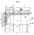
- Fig. 1 eine Draufsicht auf die erfindungsgemäße Kokille, zum Teil im Schnitt
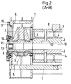
- Fig. 2 eine Seitenansicht im Schnitt A - B nach Fig. 1
- Fig. 3 einen Schnitt C - D nach Fig. 1 in vergrößerter Darstellung
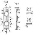
- Fig. 4 - 7 eine Stirnplatte für die Kokille, wobei
- Fig. 4 eine Seitenansicht von der Kokillenseite aus,
- Fig. 5 eine Seitenansicht der Stirnplatte nach Fig. 4 im Schnitt E - F
- Fig. 6 einen Schnitt G - H nach Fig. 4 und
- Fig. 7 einen Schnitt I - K nach Fig. 4 darstellen.
- In den Figuren sind gleiche Teile mit gleichen Bezugsziffern versehen.
- Die Fig. 1, 2 und 3 zeigen die Eingießseite einer Stranggießkokille für die Erzeugung von Flachprodukten (Brammen). Die Kokille besteht aus einem Kokillengehäuse 1 mit darin eingesetztem Kristallisator. Der Kristallisator ist gebildet aus einem Graphitteil 2, das den Formhohlraum 10 in Verbindung mit einem eingießseitig vorgeschalteten Kupfermodul 3 bildet. Der Graphitteil 2 wird von Metallplatten 4 gestützt. Die Kokille ist wassergekühlt. Dem Kupfermodul 3 wird das Kühlwasser über Anschlüsse 5 zugeführt, und die Wärme über Spalte 6 abgeführt, die von der Rückwand des Kupfermoduls 3 und einem dahinter angeordneten Verdrängungskörper 7 gebildet sind. Die Kühlung des Graphitteils 2 erfolgt in ähnlicher Weise über den Kühlmittelraum 8 zwischen Metallplatten 4 und Kokillengehäuse 1. Gemäß der Erfindung ist nun das Kupfermodul 3 eingießseitig durch eine Platte 9 über einen Teil der freien Querschnittsfläche des Formhohlraumes 10 verschlossen. Die Platte 9 kann stirnseitig an dem Kupfermodul 3 befestigt sein, bevorzugt ist sie jedoch Bestandteil des Kupfermoduls 3 selbst. Dabei geht die Innenwandfläche des Kupfermoduls 3 mit einem Radius in die Platte 9 über. Innerhalb der Platte 9 sind je nach Größe der Querschnittsfläche des Formhohlraumes 10 eine oder mehrere kreisförmige Öffnungen vorgesehen, die sich zum Formhohlraum 10 hin leicht konisch verjüngen und zur Aufnahme eines Brechringes 11, vorzugsweise aus Bornitrid, dienen. Dem Kupfermodul 3 bzw. der Platte 9 des Kupfermoduls 3 ist eine Stirnplatte 12 vorgeschaltet. Diese Stirnplatte 12 ist in den Fig. 4 - 7 dargestellt. Die Stirnplatte 12 ist in ihrer Größe so bemessen, daß die Querschnittsfläche des Kupfermoduls 3 überragt wird. Die Stirnplatte 12 weist ferner Ausnehmungen 13 auf, die nach Lage und Anzahl mit den Öffnungen für die Aufnahme der Brechringe 11 in der Platte 9 übereinstimmen. Auf der der Platte 9 zugeordneten Seite der Stirnplatte 12 sind Kanäle 14 eingearbeitet, die von Kühlflüssigkeit durchströmt werden, zur Platte 9 hin offen sind und sich von einem zum anderen Ende der Platte 12 erstrecken. Die Kanäle 14 münden einerseits an den Enden der Platte 12 in quer angeordneten Verteilerkanälen 15, die mit Anschlußstutzen 17 verbunden sind und andererseits in Ringkanäle 16, die die Ausnehmungen 13 umgeben.
- Die Erfindung ist anwendbar bei allen gängigen Abmessungen und Formaten, z. B. Rechteckformate bei Brammen, Quadrat- und Rundquerschnitte.
- Als besonders vorteilhaft wird dabei angesehen, wenn die Brechringe derart bemessen sind, daß sich ein Verhältnis zwischen dem freien Durchflußquerschnitt des Brechringes zur lichten Querschnittsfläche der Kokille von 1 zu 2,5 bis 1 zu 50 ergibt.
- Durch die Erfindung werden verschiedene Vorteile erzielt. So sind beispielsweise drei kleine Brechringe in der Herstellung billiger als ein entsprechend großer Brechring. Ferner sind kleine Brechringe mechanisch stabiler, was sich auch in einer Erhöhung der Betriebssicherheit niederschlägt. Auch wird die Vorratshaltung vereinfacht, da auf Standardringe übergegangen werden kann, die auch für verschiedene Gießquerschnitte benutzt werden können. Die Standardringe bieten ferner den Vorteil, daß der Ringsitz im Kupfermodul nicht nachgearbeittet werden muß.
Claims (5)
- Kokille für das horizontale Stranggießen von Stahl zu großformatigen Strangquerschnitten, insbesondere Flachprodukte, bestehend aus einem wassergekühlten, den Formhohlraum für den Strang bildenden Metallmantel und an der Kokille eingießseitig gehaltenen Brechring für die Schmelzenzufuhr, der die Kokille über ein anschließendes Gießrohr mit einem Schmelzenvorratsgefäß verbindet,
dadurch gekennzeichnet,
daß die Kokille eingießseitig durch eine metallische Platte (9) über einen Teil der freien Querschnittsfläche des Formhohlraumes (10) verschlossen ist, die Platte (9) eine oder mehrere Öffnungen zur Aufnahme je eines Brechringes (11) aufweist, und vor der Platte (9) eine die Platte (9) übergreifende Stirnplatte (12) in flächigem Kontakt mit der Platte (9) angeordnet ist, die Stirnplatte (12) mit Ausnehmungen (13) versehen ist, die nach Lage und Anzahl mit den Öffnungen in der Platte (9) übereinstimmen und in die Stirnplatte (12) Kanäle (14) zur Kühlwasserführung eingearbeitet sind. - Kokille nach Anspruch 1,
dadurch gekennzeichnet,
daß die Kanäle (14) in der Stirnplatte (12) in der Kontaktfläche zur Platte (9) eingearbeitet sind, die Kanäle (14) einerseits an in den Endbereichen der Stirnplatte (12) quer zu den Kanälen (14) angeordneten Verteilerkanälen (15) münden, die ihrerseits mit Anschlußstutzen (17) verbunden sind und andererseits an Ringkanäle (16) angeschlossen sind, die die Ausnehmungen (13) umgeben. - Kokille nach Anspruch 1,
dadurch gekennzeichnet,
daß die Platte (9) Bestandteil des den Eingießbereich der Kokille bildenden Kupfermoduls (3) ist. - Kokille nach den Ansprüchen 1 und 3,
dadurch gekennzeichnet,
daß der Übergang von der Platte (9) zum Kupfermodul (3) in der Querschnittsebene radial verlaufend ausgebildet ist. - Kokille nach einem der Ansprüche 1 bis 4,
dadurch gekennzeichnet,
daß das Verhältnis von freiem Durchflußquerschnitt des Brechringes zur lichten Querschnittsfläche der Kokille 1:2,5 bis 1:50 beträgt.
Applications Claiming Priority (2)
| Application Number | Priority Date | Filing Date | Title |
|---|---|---|---|
| DE4224590 | 1992-07-22 | ||
| DE4224590A DE4224590A1 (de) | 1992-07-22 | 1992-07-22 | Kokille für Horizontalstrangguß |
Publications (2)
| Publication Number | Publication Date |
|---|---|
| EP0582358A1 EP0582358A1 (de) | 1994-02-09 |
| EP0582358B1 true EP0582358B1 (de) | 1997-02-26 |
Family
ID=6464076
Family Applications (1)
| Application Number | Title | Priority Date | Filing Date |
|---|---|---|---|
| EP93250132A Expired - Lifetime EP0582358B1 (de) | 1992-07-22 | 1993-05-10 | Kokille für Horizontalstrangguss |
Country Status (6)
| Country | Link |
|---|---|
| US (1) | US5377743A (de) |
| EP (1) | EP0582358B1 (de) |
| JP (1) | JP3174203B2 (de) |
| CN (1) | CN1042002C (de) |
| AT (1) | ATE149106T1 (de) |
| DE (2) | DE4224590A1 (de) |
Families Citing this family (2)
| Publication number | Priority date | Publication date | Assignee | Title |
|---|---|---|---|---|
| RU2173603C2 (ru) * | 1999-04-02 | 2001-09-20 | Эдуард Львович Креймер | Кристаллизатор для непрерывного литья полых заготовок |
| CN103600033B (zh) * | 2013-09-22 | 2015-12-09 | 日月重工股份有限公司 | 浇注结构 |
Family Cites Families (17)
| Publication number | Priority date | Publication date | Assignee | Title |
|---|---|---|---|---|
| CH440570A (de) * | 1964-11-27 | 1967-07-31 | Deutsche Edelstahlwerke Ag | Vorrichtung mit Giessdüse und Giesskopf zum Stranggiessen von hochschmelzenden Metallen, insbesondere Stahl |
| US3506063A (en) * | 1967-05-18 | 1970-04-14 | Ashmore Benson Pease & Co Ltd | Continuous casting |
| US3593778A (en) * | 1968-03-07 | 1971-07-20 | Kaiser Aluminium Chem Corp | Continuous casting apparatus |
| SU267019A1 (ru) * | 1968-11-29 | 1986-08-23 | Ugodnikov A L | Кристаллизатор горизонтальной установки непрерывной разливки металлов |
| GB1312243A (en) * | 1969-03-21 | 1973-04-04 | Ashmore Benson Pease & Co Ltd | Continuous casting apparatus |
| GB1337971A (en) * | 1970-01-07 | 1973-11-21 | Ashmore Benson Pease & Co Ltd | Continuous casting apparatus |
| US3730251A (en) * | 1971-06-21 | 1973-05-01 | Gen Motors Corp | Method of continuous casting |
| DE2520091A1 (de) * | 1975-05-06 | 1976-11-18 | Davy Loewy Ltd | Kokille fuer strangguss |
| JPS6054818B2 (ja) * | 1979-07-10 | 1985-12-02 | 日本鋼管株式会社 | 水平連続鋳造用タンデイツシユとモ−ルドとの結合方法および装置 |
| JPS61144244A (ja) * | 1984-12-18 | 1986-07-01 | Kawasaki Heavy Ind Ltd | 連続鋳造設備 |
| CA1256668A (en) * | 1984-12-28 | 1989-07-04 | Nippon Kokan Kabushiki Kaisha | Horizontal type continuous casting machine for casting molten steel into cast steel strand |
| US4693296A (en) * | 1985-11-07 | 1987-09-15 | Flo-Con Systems, Inc. | Composite break ring for continuous casting |
| JPS62151249A (ja) * | 1985-12-25 | 1987-07-06 | Kawasaki Heavy Ind Ltd | 水平連続鋳造設備 |
| JPS62224453A (ja) * | 1986-03-25 | 1987-10-02 | Sumitomo Metal Ind Ltd | 連続鋳造における接続耐火物の取付方法 |
| US4799533A (en) * | 1986-06-20 | 1989-01-24 | Steel Casting Engineering, Ltd. | Horizontal continuous casting mold |
| US4774996A (en) * | 1986-09-29 | 1988-10-04 | Steel Casting Engineering, Ltd. | Moving plate continuous casting aftercooler |
| GB8900739D0 (en) * | 1989-01-13 | 1989-03-08 | Davy Mckee Sheffield | Horizontal continuous casting apparatus |
-
1992
- 1992-07-22 DE DE4224590A patent/DE4224590A1/de not_active Withdrawn
-
1993
- 1993-05-10 EP EP93250132A patent/EP0582358B1/de not_active Expired - Lifetime
- 1993-05-10 AT AT93250132T patent/ATE149106T1/de not_active IP Right Cessation
- 1993-05-10 DE DE59305521T patent/DE59305521D1/de not_active Expired - Fee Related
- 1993-06-22 CN CN93107449A patent/CN1042002C/zh not_active Expired - Fee Related
- 1993-06-30 JP JP18679893A patent/JP3174203B2/ja not_active Expired - Fee Related
- 1993-07-16 US US08/092,552 patent/US5377743A/en not_active Expired - Fee Related
Also Published As
| Publication number | Publication date |
|---|---|
| DE4224590A1 (de) | 1994-01-27 |
| EP0582358A1 (de) | 1994-02-09 |
| US5377743A (en) | 1995-01-03 |
| DE59305521D1 (de) | 1997-04-03 |
| CN1082958A (zh) | 1994-03-02 |
| ATE149106T1 (de) | 1997-03-15 |
| JPH0663702A (ja) | 1994-03-08 |
| JP3174203B2 (ja) | 2001-06-11 |
| CN1042002C (zh) | 1999-02-10 |
Similar Documents
| Publication | Publication Date | Title |
|---|---|---|
| EP0589998B1 (de) | Tauchgiessrohr für dünnbramme | |
| EP0254909B1 (de) | Feuerfestes Giessrohr | |
| DE1242803B (de) | Gekuehlte Kokille zum waagerechten Stranggiessen | |
| EP0149734A2 (de) | Kokille zum Stranggiessen von Stahlband | |
| DE3501422A1 (de) | Durchlaufkokille fuer eine stranggiessanlage | |
| DE3621322C2 (de) | ||
| DE2606370A1 (de) | Giessverfahren und giessform zu seiner durchfuehrung | |
| DE2747746A1 (de) | Zwischenpfannen-giesschnauze | |
| EP2140956B1 (de) | Eingussvorrichtung für Metallschmelzen | |
| DE69213160T2 (de) | Gebogene Kokille zum Bogenstranggiessen von dünnen Brammen | |
| EP0582358A1 (de) | Kokille für Horizontalstrangguss | |
| DE2132294A1 (de) | Verfahren und Vorrichtung zum Giessen von Metallschmelze | |
| EP0083745B1 (de) | Verlängerte Ausgussdüse für Zwischenbehälter | |
| DE4116723C1 (en) | Immersion tundish outlet giving quiescent melt flow into mould - includes channel with nozzle shape at inlet to receive stopper, with narrowest section at transition to channel | |
| EP0814929B1 (de) | Tauchausguss zum giessen von metall | |
| EP3130414B1 (de) | Schmelzmetallurgische anlage, umfassend eine kokille | |
| EP1042087B1 (de) | Einrichtung zur zuführung von metallschmelze | |
| DE2548585B2 (de) | Vorrichtung zum stranggiessen von stahl | |
| DE3149399C1 (de) | Tauchausguß | |
| EP0900609B1 (de) | Tauchgiessrohr zum Einleiten von Schmelze aus einem Giess- oder Zwischenbehälter in eine Kokille | |
| DE2834746A1 (de) | Abschirmvorrichtung fuer einen giessstrahl aus fluessigem metall | |
| DE2114505C3 (de) | Ofenabhängige Stranggießkokille | |
| DE4321492C1 (de) | Horizontal-Stranggießanlage | |
| AT522037B1 (de) | Kokilleneinheit zum Stranggießen von Metallprodukten sowie Stranggießanlage | |
| DE2800458C3 (de) | Elektromagnetische Stranggießkokille |
Legal Events
| Date | Code | Title | Description |
|---|---|---|---|
| PUAI | Public reference made under article 153(3) epc to a published international application that has entered the european phase |
Free format text: ORIGINAL CODE: 0009012 |
|
| AK | Designated contracting states |
Kind code of ref document: A1 Designated state(s): AT DE ES FR GB |
|
| 17P | Request for examination filed |
Effective date: 19940125 |
|
| GRAG | Despatch of communication of intention to grant |
Free format text: ORIGINAL CODE: EPIDOS AGRA |
|
| 17Q | First examination report despatched |
Effective date: 19960328 |
|
| GRAH | Despatch of communication of intention to grant a patent |
Free format text: ORIGINAL CODE: EPIDOS IGRA |
|
| GRAH | Despatch of communication of intention to grant a patent |
Free format text: ORIGINAL CODE: EPIDOS IGRA |
|
| GRAA | (expected) grant |
Free format text: ORIGINAL CODE: 0009210 |
|
| AK | Designated contracting states |
Kind code of ref document: B1 Designated state(s): AT DE ES FR GB |
|
| PG25 | Lapsed in a contracting state [announced via postgrant information from national office to epo] |
Ref country code: GB Effective date: 19970226 Ref country code: FR Effective date: 19970226 Ref country code: ES Free format text: THE PATENT HAS BEEN ANNULLED BY A DECISION OF A NATIONAL AUTHORITY Effective date: 19970226 |
|
| REF | Corresponds to: |
Ref document number: 149106 Country of ref document: AT Date of ref document: 19970315 Kind code of ref document: T |
|
| REF | Corresponds to: |
Ref document number: 59305521 Country of ref document: DE Date of ref document: 19970403 |
|
| PG25 | Lapsed in a contracting state [announced via postgrant information from national office to epo] |
Ref country code: AT Free format text: LAPSE BECAUSE OF NON-PAYMENT OF DUE FEES Effective date: 19970510 |
|
| EN | Fr: translation not filed | ||
| GBV | Gb: ep patent (uk) treated as always having been void in accordance with gb section 77(7)/1977 [no translation filed] |
Effective date: 19970226 |
|
| PLBE | No opposition filed within time limit |
Free format text: ORIGINAL CODE: 0009261 |
|
| 26N | No opposition filed | ||
| PGFP | Annual fee paid to national office [announced via postgrant information from national office to epo] |
Ref country code: DE Payment date: 20020511 Year of fee payment: 10 |
|
| PG25 | Lapsed in a contracting state [announced via postgrant information from national office to epo] |
Ref country code: DE Free format text: LAPSE BECAUSE OF NON-PAYMENT OF DUE FEES Effective date: 20031202 |