EP0578157B1 - Presse zum Einpressen von Steckverbindern in Leiterplatten - Google Patents
Presse zum Einpressen von Steckverbindern in Leiterplatten Download PDFInfo
- Publication number
- EP0578157B1 EP0578157B1 EP93110653A EP93110653A EP0578157B1 EP 0578157 B1 EP0578157 B1 EP 0578157B1 EP 93110653 A EP93110653 A EP 93110653A EP 93110653 A EP93110653 A EP 93110653A EP 0578157 B1 EP0578157 B1 EP 0578157B1
- Authority
- EP
- European Patent Office
- Prior art keywords
- press
- force
- spring
- fitting
- arm
- Prior art date
- Legal status (The legal status is an assumption and is not a legal conclusion. Google has not performed a legal analysis and makes no representation as to the accuracy of the status listed.)
- Expired - Lifetime
Links
- 238000000034 method Methods 0.000 claims description 10
- 238000010276 construction Methods 0.000 claims 1
- 238000006073 displacement reaction Methods 0.000 description 2
- 208000031872 Body Remains Diseases 0.000 description 1
- 238000005452 bending Methods 0.000 description 1
- 230000000284 resting effect Effects 0.000 description 1
- 239000000725 suspension Substances 0.000 description 1
Images


Classifications
-
- H—ELECTRICITY
- H01—ELECTRIC ELEMENTS
- H01R—ELECTRICALLY-CONDUCTIVE CONNECTIONS; STRUCTURAL ASSOCIATIONS OF A PLURALITY OF MUTUALLY-INSULATED ELECTRICAL CONNECTING ELEMENTS; COUPLING DEVICES; CURRENT COLLECTORS
- H01R43/00—Apparatus or processes specially adapted for manufacturing, assembling, maintaining, or repairing of line connectors or current collectors or for joining electric conductors
- H01R43/20—Apparatus or processes specially adapted for manufacturing, assembling, maintaining, or repairing of line connectors or current collectors or for joining electric conductors for assembling or disassembling contact members with insulating base, case or sleeve
- H01R43/205—Apparatus or processes specially adapted for manufacturing, assembling, maintaining, or repairing of line connectors or current collectors or for joining electric conductors for assembling or disassembling contact members with insulating base, case or sleeve with a panel or printed circuit board
Definitions
- the invention relates to a press for pressing connectors into printed circuit boards, in particular press with a C-shaped press body, the printed circuit board, in the bores of which the press-in sections of the contact element ends of a connector are pressed by means of a press ram / pressing tool, rests on a press table, and wherein the Press is provided with resilient, resilient means.
- Presses with a C-shaped press base body are preferably used for pressing plug-in connectors into printed circuit boards, since the press body, which is open on one side, is particularly well suited to being able to hold printed circuit boards of various formats for pressing.
- press-in forces When pressing multi-pin connectors into printed circuit boards, high press-in forces are required, which can be up to 150 N for each contact end to be pressed in. With plug connectors used today with up to 500 contacts, press-in forces of up to 75 kN can then be applied.
- a C-shaped press body tends to spring elastically.
- the press ram and the press tool associated with it move originally from it vertical or horizontal position by an angle corresponding to the spring deflection.
- This displacement / misalignment has the result that, in particular, connectors to be pressed in which are arranged longitudinally in the opening direction of the C-shaped press are pressed obliquely into the printed circuit board, so that one end of the connector is pressed into the printed circuit board until the support body stops, but the other end is not completely pressed in until it stops.
- the invention is based on the object of designing a commercially available, C-shaped press such that a springing open of the press body remains without influence on the required plane-parallel pressing of, in particular, connectors arranged longitudinally to the press opening into the printed circuit board.
- the resilient, resilient means are arranged in such a way that they prevent the inclination of the press-in tool, i.e. counteract the inclination of the underside of the press-in tool in relation to the printed circuit board or the connector to be pressed in, when the arms of the press spring open during the press-in process, so that the underside of the press-in tool is always plane-parallel to the printed circuit board, i.e. that the tool always acts vertically on the connector to be pressed.
- the advantages achieved by the invention are, in particular, that a bending of the arms of the C-shaped press body occurring during the press-in process and the resulting misalignment of the press-in tool with respect to the printed circuit board or the plug-in connector to be pressed in are compensated for, so that the press-in tool is plane-parallel during the press-in process to the circuit board on the press table.
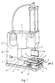
- the press shown in FIG. 1 has an essentially C-shaped press body 1, a press cylinder with a vertically acting press ram 3 being arranged on the upper arm 2 and a press table 5 being arranged on the lower arm 4.
- the press table there is a printed circuit board 6 with a connector 7 placed thereon, the contact element ends of which are pressed into holes in the printed circuit board when the press ram is pressed down by the press tool 8 connected thereto.
- the connector is placed on the circuit board so that its longitudinal axis runs in the direction of the opening of the C-shaped press body.
- the two arms 2, 4 of the press body become C-shaped due to the elasticity that is always present Body bent out with relatively wide arms by the forces occurring during the pressing process, so that the bottom 9 of the press tool no longer runs plane-parallel to the surface 10 of the lower arm 4 with the press table.
- the connector is then pressed obliquely into the circuit board in such a way that the front end 11 of the connector facing away from the opening of the C's is not completely pressed into the circuit board holes.
- the front end 12 of the press table is rotatably / pivotably mounted about the axis X. Furthermore, a spring element 13 is arranged under the other, rear end of the press table, on which the press table rests.
- a support part 14 is provided, on which a plate spring 15 is fastened by means of a pin 16.
- the pin is movably held in the supporting part in the vertical direction, the plate spring being prestressed by means of a nut 17.
- the spring characteristic of the spring element ie the plate spring, is selected in accordance with the spring characteristic of the arms of the C-shaped press body.
- the rear end of the press table is deflected / pivoted back by an amount Y when the press-in force acts on it corresponds to the spring deflection of the arms 2.4, so that the press-in tool acts exactly perpendicularly on the press table / the connector during the actual press-in process.
- the spring element is fastened horizontally displaceably to the lower press arm.
- a slot 18 is formed in the press arm, through which a clamping screw 19 is guided, with which the spring element can be locked in different positions (see FIG. 1).
- a modified press is shown in FIG. It is provided that the press cylinder 20 with the press ram 3 and the press tool 8 is arranged via a joint 21 at the lower end of the upper arm 2 of the press body.
- a tension spring 22 as a spring element between the press cylinder and the upper end of the arm 2 pulls the press cylinder against a stop 23 on the upper arm.
- FIG. 4 a further modified press is shown in FIG. 4.
- the press-in tool 8 ' is of divided design, namely an upper and a lower part 24, 25 are provided which are connected to one another in an articulated manner about a front axis X'.
- a spring element 13 ' is arranged between the two parts, which acts in accordance with the spring element 13 described at the beginning and one when the arms 2, 4 of the press body spring open Compensation for the resulting misalignment of the press tool in relation to the connector to be pressed.
- the axis of rotation Z about which the arms 2, 4 of the press spring open during the press-in process, is approximately at the height of the press table, so that the horizontal displacement (relative movement) between the vertical axes of the press-in tool and the connector is avoided .
- This greater elasticity of the connection of the lower arm 4 to the vertical arm 26 of the press can be achieved, for example, in that the vertical arm is designed with a reduced cross section at the height of the press table 5.
Landscapes
- Engineering & Computer Science (AREA)
- Manufacturing & Machinery (AREA)
- Manufacturing Of Electrical Connectors (AREA)
- Press Drives And Press Lines (AREA)
Applications Claiming Priority (2)
| Application Number | Priority Date | Filing Date | Title |
|---|---|---|---|
| DE4222575A DE4222575C1 (enExample) | 1992-07-09 | 1992-07-09 | |
| DE4222575 | 1992-07-09 |
Publications (2)
| Publication Number | Publication Date |
|---|---|
| EP0578157A1 EP0578157A1 (de) | 1994-01-12 |
| EP0578157B1 true EP0578157B1 (de) | 1996-11-06 |
Family
ID=6462851
Family Applications (1)
| Application Number | Title | Priority Date | Filing Date |
|---|---|---|---|
| EP93110653A Expired - Lifetime EP0578157B1 (de) | 1992-07-09 | 1993-07-03 | Presse zum Einpressen von Steckverbindern in Leiterplatten |
Country Status (2)
| Country | Link |
|---|---|
| EP (1) | EP0578157B1 (enExample) |
| DE (2) | DE4222575C1 (enExample) |
Family Cites Families (7)
| Publication number | Priority date | Publication date | Assignee | Title |
|---|---|---|---|---|
| US2944330A (en) * | 1955-11-08 | 1960-07-12 | Illinois Tool Works | Terminal clip structure and method and apparatus for applying same |
| US4385719A (en) * | 1981-04-16 | 1983-05-31 | Mechanical Applications, Inc. | Machine for inserting spring pins |
| CH644291A5 (en) * | 1981-05-15 | 1984-07-31 | Microbo Sa | Orientation device with a centre of rotation outside a machine (assembly) tool |
| DE3242751A1 (de) * | 1982-04-02 | 1983-10-13 | VEB Stahl- und Walzwerk Gröditz im VEB Rohrkombinat, DDR 8402 Gröditz | Einrichtung zur werkstueckbearbeitung |
| US4553322A (en) * | 1984-05-16 | 1985-11-19 | Amp Incorporated | Floating locator head for application tooling |
| US4590673A (en) * | 1984-06-11 | 1986-05-27 | Amp Incorporated | Force-fitting components into a workpiece |
| US4880219A (en) * | 1988-04-27 | 1989-11-14 | Robert Nemirovsky | Tilting apparatus |
-
1992
- 1992-07-09 DE DE4222575A patent/DE4222575C1/de not_active Expired - Fee Related
-
1993
- 1993-07-03 DE DE59304394T patent/DE59304394D1/de not_active Expired - Lifetime
- 1993-07-03 EP EP93110653A patent/EP0578157B1/de not_active Expired - Lifetime
Also Published As
| Publication number | Publication date |
|---|---|
| DE4222575C1 (enExample) | 1993-08-12 |
| DE59304394D1 (de) | 1996-12-12 |
| EP0578157A1 (de) | 1994-01-12 |
Similar Documents
| Publication | Publication Date | Title |
|---|---|---|
| DE3873586T2 (de) | Einstellbare traegeranordnung. | |
| DE2630896A1 (de) | Vorrichtung zum abbiegen grossflaechiger bauteile | |
| DE10223637B4 (de) | Biege-Werkzeug | |
| EP0934131A1 (de) | Biegemaschine | |
| EP0611258B1 (de) | Tampondruckmaschine | |
| EP0476244A1 (de) | Greiferfinger einer Greiferwelle einer Bogendruckmaschine | |
| DE69324496T2 (de) | Fokussierarmverstelleinrichtung für einen overheadprojektor | |
| EP0578157B1 (de) | Presse zum Einpressen von Steckverbindern in Leiterplatten | |
| DE10102488A1 (de) | Vorrichtung zur Höheneinstellung einer Mehrzahl von Werkzeughaltern für eine Abkantpresse | |
| DE3719483A1 (de) | Schraubklemme zum anschluss elektrischer leitungen | |
| EP3799588B1 (de) | Kupplungsabstützung für eine mittelpufferkupplung eines schienenfahrzeugs | |
| DE3240662A1 (de) | Vorrichtung zur lagefixierung von werkstuecktraegern auf werkzeugmaschinen | |
| DE3042677A1 (de) | Schraubstock | |
| DE2640691C3 (de) | Vorrichtung zur Schwinglagerung eines ersten Körpers an einem zweiten Körper | |
| EP2581144A1 (de) | Biegemaschine | |
| EP0580077B1 (de) | Tisch mit einer beweglichen Arbeitsplatte | |
| DE4001724A1 (de) | Halteteil fuer eine leuchte | |
| DE2825518A1 (de) | Biegemaschine | |
| DE291900C (enExample) | ||
| AT166136B (de) | Zeichenvorrichtung | |
| DE846195C (de) | Ausgleichbacken fuer Maschinenschraubstoecke | |
| DE29814796U1 (de) | Verbesserte Struktur einer Werkstück-Feineinstellung/Kompensation | |
| EP0016878B1 (de) | Vorrichtung zum Verstellen eines schwenkbaren Bettrahmenteils | |
| DE8706641U1 (de) | Steckverbinder für IC-Baueinheiten | |
| DE2407191C3 (de) | Abkantvorrichtung für Bleche |
Legal Events
| Date | Code | Title | Description |
|---|---|---|---|
| PUAI | Public reference made under article 153(3) epc to a published international application that has entered the european phase |
Free format text: ORIGINAL CODE: 0009012 |
|
| AK | Designated contracting states |
Kind code of ref document: A1 Designated state(s): DE FR GB IT |
|
| 17P | Request for examination filed |
Effective date: 19940111 |
|
| 17Q | First examination report despatched |
Effective date: 19950220 |
|
| GRAG | Despatch of communication of intention to grant |
Free format text: ORIGINAL CODE: EPIDOS AGRA |
|
| GRAH | Despatch of communication of intention to grant a patent |
Free format text: ORIGINAL CODE: EPIDOS IGRA |
|
| GRAH | Despatch of communication of intention to grant a patent |
Free format text: ORIGINAL CODE: EPIDOS IGRA |
|
| GRAA | (expected) grant |
Free format text: ORIGINAL CODE: 0009210 |
|
| AK | Designated contracting states |
Kind code of ref document: B1 Designated state(s): DE FR GB IT |
|
| ITF | It: translation for a ep patent filed | ||
| ET | Fr: translation filed | ||
| REF | Corresponds to: |
Ref document number: 59304394 Country of ref document: DE Date of ref document: 19961212 |
|
| RAP2 | Party data changed (patent owner data changed or rights of a patent transferred) |
Owner name: HARTING KG |
|
| GBT | Gb: translation of ep patent filed (gb section 77(6)(a)/1977) |
Effective date: 19970204 |
|
| RAP2 | Party data changed (patent owner data changed or rights of a patent transferred) |
Owner name: HARTING KGAA |
|
| PLBE | No opposition filed within time limit |
Free format text: ORIGINAL CODE: 0009261 |
|
| STAA | Information on the status of an ep patent application or granted ep patent |
Free format text: STATUS: NO OPPOSITION FILED WITHIN TIME LIMIT |
|
| 26N | No opposition filed | ||
| REG | Reference to a national code |
Ref country code: GB Ref legal event code: IF02 |
|
| REG | Reference to a national code |
Ref country code: FR Ref legal event code: TP Ref country code: FR Ref legal event code: CD |
|
| PG25 | Lapsed in a contracting state [announced via postgrant information from national office to epo] |
Ref country code: IT Free format text: LAPSE BECAUSE OF NON-PAYMENT OF DUE FEES;WARNING: LAPSES OF ITALIAN PATENTS WITH EFFECTIVE DATE BEFORE 2007 MAY HAVE OCCURRED AT ANY TIME BEFORE 2007. THE CORRECT EFFECTIVE DATE MAY BE DIFFERENT FROM THE ONE RECORDED. Effective date: 20050703 |
|
| REG | Reference to a national code |
Ref country code: GB Ref legal event code: 732E Free format text: REGISTERED BETWEEN 20120112 AND 20120118 |
|
| PGFP | Annual fee paid to national office [announced via postgrant information from national office to epo] |
Ref country code: GB Payment date: 20120726 Year of fee payment: 20 |
|
| PGFP | Annual fee paid to national office [announced via postgrant information from national office to epo] |
Ref country code: DE Payment date: 20120713 Year of fee payment: 20 Ref country code: FR Payment date: 20120808 Year of fee payment: 20 |
|
| REG | Reference to a national code |
Ref country code: DE Ref legal event code: R071 Ref document number: 59304394 Country of ref document: DE |
|
| REG | Reference to a national code |
Ref country code: GB Ref legal event code: PE20 Expiry date: 20130702 |
|
| PG25 | Lapsed in a contracting state [announced via postgrant information from national office to epo] |
Ref country code: DE Free format text: LAPSE BECAUSE OF EXPIRATION OF PROTECTION Effective date: 20130704 |
|
| PG25 | Lapsed in a contracting state [announced via postgrant information from national office to epo] |
Ref country code: GB Free format text: LAPSE BECAUSE OF EXPIRATION OF PROTECTION Effective date: 20130702 |