EP0578157B1 - Press for force fitting of connectors in printed circuit boards - Google Patents
Press for force fitting of connectors in printed circuit boards Download PDFInfo
- Publication number
- EP0578157B1 EP0578157B1 EP93110653A EP93110653A EP0578157B1 EP 0578157 B1 EP0578157 B1 EP 0578157B1 EP 93110653 A EP93110653 A EP 93110653A EP 93110653 A EP93110653 A EP 93110653A EP 0578157 B1 EP0578157 B1 EP 0578157B1
- Authority
- EP
- European Patent Office
- Prior art keywords
- press
- force
- spring
- fitting
- arm
- Prior art date
- Legal status (The legal status is an assumption and is not a legal conclusion. Google has not performed a legal analysis and makes no representation as to the accuracy of the status listed.)
- Expired - Lifetime
Links
Images


Classifications
-
- H—ELECTRICITY
- H01—ELECTRIC ELEMENTS
- H01R—ELECTRICALLY-CONDUCTIVE CONNECTIONS; STRUCTURAL ASSOCIATIONS OF A PLURALITY OF MUTUALLY-INSULATED ELECTRICAL CONNECTING ELEMENTS; COUPLING DEVICES; CURRENT COLLECTORS
- H01R43/00—Apparatus or processes specially adapted for manufacturing, assembling, maintaining, or repairing of line connectors or current collectors or for joining electric conductors
- H01R43/20—Apparatus or processes specially adapted for manufacturing, assembling, maintaining, or repairing of line connectors or current collectors or for joining electric conductors for assembling or disassembling contact members with insulating base, case or sleeve
- H01R43/205—Apparatus or processes specially adapted for manufacturing, assembling, maintaining, or repairing of line connectors or current collectors or for joining electric conductors for assembling or disassembling contact members with insulating base, case or sleeve with a panel or printed circuit board
Definitions
- the invention relates to a press for pressing connectors into printed circuit boards, in particular press with a C-shaped press body, the printed circuit board, in the bores of which the press-in sections of the contact element ends of a connector are pressed by means of a press ram / pressing tool, rests on a press table, and wherein the Press is provided with resilient, resilient means.
- Presses with a C-shaped press base body are preferably used for pressing plug-in connectors into printed circuit boards, since the press body, which is open on one side, is particularly well suited to being able to hold printed circuit boards of various formats for pressing.
- press-in forces When pressing multi-pin connectors into printed circuit boards, high press-in forces are required, which can be up to 150 N for each contact end to be pressed in. With plug connectors used today with up to 500 contacts, press-in forces of up to 75 kN can then be applied.
- a C-shaped press body tends to spring elastically.
- the press ram and the press tool associated with it move originally from it vertical or horizontal position by an angle corresponding to the spring deflection.
- This displacement / misalignment has the result that, in particular, connectors to be pressed in which are arranged longitudinally in the opening direction of the C-shaped press are pressed obliquely into the printed circuit board, so that one end of the connector is pressed into the printed circuit board until the support body stops, but the other end is not completely pressed in until it stops.
- the invention is based on the object of designing a commercially available, C-shaped press such that a springing open of the press body remains without influence on the required plane-parallel pressing of, in particular, connectors arranged longitudinally to the press opening into the printed circuit board.
- the resilient, resilient means are arranged in such a way that they prevent the inclination of the press-in tool, i.e. counteract the inclination of the underside of the press-in tool in relation to the printed circuit board or the connector to be pressed in, when the arms of the press spring open during the press-in process, so that the underside of the press-in tool is always plane-parallel to the printed circuit board, i.e. that the tool always acts vertically on the connector to be pressed.
- the advantages achieved by the invention are, in particular, that a bending of the arms of the C-shaped press body occurring during the press-in process and the resulting misalignment of the press-in tool with respect to the printed circuit board or the plug-in connector to be pressed in are compensated for, so that the press-in tool is plane-parallel during the press-in process to the circuit board on the press table.
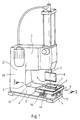
- the press shown in FIG. 1 has an essentially C-shaped press body 1, a press cylinder with a vertically acting press ram 3 being arranged on the upper arm 2 and a press table 5 being arranged on the lower arm 4.
- the press table there is a printed circuit board 6 with a connector 7 placed thereon, the contact element ends of which are pressed into holes in the printed circuit board when the press ram is pressed down by the press tool 8 connected thereto.
- the connector is placed on the circuit board so that its longitudinal axis runs in the direction of the opening of the C-shaped press body.
- the two arms 2, 4 of the press body become C-shaped due to the elasticity that is always present Body bent out with relatively wide arms by the forces occurring during the pressing process, so that the bottom 9 of the press tool no longer runs plane-parallel to the surface 10 of the lower arm 4 with the press table.
- the connector is then pressed obliquely into the circuit board in such a way that the front end 11 of the connector facing away from the opening of the C's is not completely pressed into the circuit board holes.
- the front end 12 of the press table is rotatably / pivotably mounted about the axis X. Furthermore, a spring element 13 is arranged under the other, rear end of the press table, on which the press table rests.
- a support part 14 is provided, on which a plate spring 15 is fastened by means of a pin 16.
- the pin is movably held in the supporting part in the vertical direction, the plate spring being prestressed by means of a nut 17.
- the spring characteristic of the spring element ie the plate spring, is selected in accordance with the spring characteristic of the arms of the C-shaped press body.
- the rear end of the press table is deflected / pivoted back by an amount Y when the press-in force acts on it corresponds to the spring deflection of the arms 2.4, so that the press-in tool acts exactly perpendicularly on the press table / the connector during the actual press-in process.
- the spring element is fastened horizontally displaceably to the lower press arm.
- a slot 18 is formed in the press arm, through which a clamping screw 19 is guided, with which the spring element can be locked in different positions (see FIG. 1).
- a modified press is shown in FIG. It is provided that the press cylinder 20 with the press ram 3 and the press tool 8 is arranged via a joint 21 at the lower end of the upper arm 2 of the press body.
- a tension spring 22 as a spring element between the press cylinder and the upper end of the arm 2 pulls the press cylinder against a stop 23 on the upper arm.
- FIG. 4 a further modified press is shown in FIG. 4.
- the press-in tool 8 ' is of divided design, namely an upper and a lower part 24, 25 are provided which are connected to one another in an articulated manner about a front axis X'.
- a spring element 13 ' is arranged between the two parts, which acts in accordance with the spring element 13 described at the beginning and one when the arms 2, 4 of the press body spring open Compensation for the resulting misalignment of the press tool in relation to the connector to be pressed.
- the axis of rotation Z about which the arms 2, 4 of the press spring open during the press-in process, is approximately at the height of the press table, so that the horizontal displacement (relative movement) between the vertical axes of the press-in tool and the connector is avoided .
- This greater elasticity of the connection of the lower arm 4 to the vertical arm 26 of the press can be achieved, for example, in that the vertical arm is designed with a reduced cross section at the height of the press table 5.
Landscapes
- Engineering & Computer Science (AREA)
- Manufacturing & Machinery (AREA)
- Manufacturing Of Electrical Connectors (AREA)
- Press Drives And Press Lines (AREA)
Description
Die Erfindung betrifft eine Presse zum Einpressen von Steckverbindern in Leiterplatten, insbesondere Presse mit einem C-förmigen Pressenkörper, wobei die Leiterplatte, in deren Bohrungen die Einpreßabschnitte der Kontaktelementenden eines Steckverbinders mittels eines Preßstempels/ Preßwerkzeuges eingepreßt werden, auf einem Pressentisch aufliegt, und wobei die Presse mit federelastischen, nachgiebigen Mitteln versehen ist.The invention relates to a press for pressing connectors into printed circuit boards, in particular press with a C-shaped press body, the printed circuit board, in the bores of which the press-in sections of the contact element ends of a connector are pressed by means of a press ram / pressing tool, rests on a press table, and wherein the Press is provided with resilient, resilient means.
Vorzugsweise werden zum Einpressen von Steckverbindern in Leiterplatten Pressen mit einem C-förmigen Pressengrundkörper verwendet, da der einseitig offene Pressenkörper besonders gut geeignet ist, um Leiterplatten verschiedenster Formate zum Verpressen aufnehmen zu können.Presses with a C-shaped press base body are preferably used for pressing plug-in connectors into printed circuit boards, since the press body, which is open on one side, is particularly well suited to being able to hold printed circuit boards of various formats for pressing.
Beim Einpressen von hochpoligen Steckverbindern in Leiterplatten sind hohe Einpreßkräfte erforderlich, die pro einzupressendem Kontaktende bis zu 150 N betragen können. Bei heutzutage angewendeten Steckverbindern mit bis zu 500 Kontakten können dabei dann Einpreßkräfte von bis zu 75 kN aufzubringen sein.When pressing multi-pin connectors into printed circuit boards, high press-in forces are required, which can be up to 150 N for each contact end to be pressed in. With plug connectors used today with up to 500 contacts, press-in forces of up to 75 kN can then be applied.
Bei derart hohen Einpreßkräften zeigt ein C-förmiger Pressenkörper jedoch die Neigung, elastisch aufzufedern. Dabei verlagert sich der Pressenstößel und das damit verbundene Einpreßwerkzeug jedoch aus seiner ursprünglich senkrechten bzw. waagerechten Stellung um einen der Auffederung entsprechenden Winkel. Diese Verlagerung/ Schiefstellung hat zur Folge, daß insbesondere längs in Öffnungsrichtung der C-förmigen Presse angeordnete einzupressende Steckverbinder schräg in die Leiterplatte eingepreßt werden, sodaß das eine Ende des Steckverbinders zwar bis zum Anschlag des Trägerkörpers in die Leiterplatte eingepreßt ist, das andere Ende jedoch eben nicht vollständig bis zum Anschlag eingepreßt ist.With such high press-in forces, however, a C-shaped press body tends to spring elastically. However, the press ram and the press tool associated with it move originally from it vertical or horizontal position by an angle corresponding to the spring deflection. This displacement / misalignment has the result that, in particular, connectors to be pressed in which are arranged longitudinally in the opening direction of the C-shaped press are pressed obliquely into the printed circuit board, so that one end of the connector is pressed into the printed circuit board until the support body stops, but the other end is not completely pressed in until it stops.
Die vorstehend erwähnten Probleme treten verstärkt mit zunehmender Steckverbinderlänge auf.The above-mentioned problems increase with increasing connector length.
Zwar könnte diesem Problem durch Verwendung von Pressen mit Drei- oder Vier-Säulengestellen, wobei die Leiterplatte/der einzupressende Steckverbinder dann zwischen den Säulen angeordnet ist, begegnet werden, jedoch ist bei dieser Pressenart der eigentliche Arbeitsraum zwischen den Säulen entweder sehr eng oder die Pressen weisen unverhältnismäßig große Abmessungen auf.Although this problem could be countered by using presses with three or four column frames, with the printed circuit board / the connector to be pressed in between the columns, the actual working space between the columns is either very narrow or the presses with this type of press have disproportionately large dimensions.
Andererseits könnte das Problem des Auffederns bei C-förmigen Pressen durch mechanisch weit überdimensionierte Pressen/Pressenkörper gemildert werden, jedoch sind auch derartige Pressen für den Anwender unakzeptabel groß, schwer und kostspielig.On the other hand, the spring-back problem in the case of C-shaped presses could be alleviated by presses / press bodies which are mechanically overdimensioned, but such presses are also unacceptably large, heavy and expensive for the user.
Aus der US-A-2 994 330 ist es bekannt, eine Presse zum Einpressen von Kontaktteilen in eine Trägerplatte mit federelastischen Mitteln zu versehen, wobei die Trägerplatte auf einem durch Federn abgestützten Tisch aufliegt. Hierbei dient die Federung zum Toleranzausgleich von unterschiedlich dicken Kontaktteilen bzw. Trägerplatten, damit weder der Preßstempel noch die Kontaktteile mit einem übermäßig hohem Preßdruck gegen Ende des Einpreßhubes beaufschlagt werden.From US-A-2 994 330 it is known to provide a press for pressing contact parts into a carrier plate with spring-elastic means, the carrier plate resting on a table supported by springs. Here, the suspension is used to compensate for the tolerance of contact parts or carrier plates of different thicknesses, so that neither the press ram nor the contact parts are subjected to an excessively high press pressure towards the end of the press-in stroke.
Der Erfindung liegt nunmehr die Aufgabe zugrunde, eine handelsübliche, C-förmige Presse dahingehend auszubilden, daß ein Auffedern des Pressenkörpers ohne Einfluß auf das erforderliche planparallele Einpressen von insbesondere längs zur Pressenöffnung angeordneten Steckverbindern in die Leiterplatte bleibt.The invention is based on the object of designing a commercially available, C-shaped press such that a springing open of the press body remains without influence on the required plane-parallel pressing of, in particular, connectors arranged longitudinally to the press opening into the printed circuit board.
Diese Aufgabe wird dadurch gelöst, daß die federelastischen, nachgiebigen Mittel derart angeordnet sind, daß sie der Schiefstellung des Einpreßwerkzeuges, d.h. der Schiefstellung der Unterseite des Einpreßwerkzeuges in Bezug auf die Leiterplatte bzw. den einzupressenden Steckverbinder, beim Auffedern der Arme der Presse beim Einpreßvorgang entgegenwirken, so daß die Unterseite des Einpreßwerkzeuges stets planparallel zur Leiterplatte ist, d.h. daß das Werkzeug stets senkrecht auf den einzupressenden Steckverbinder wirkt.This object is achieved in that the resilient, resilient means are arranged in such a way that they prevent the inclination of the press-in tool, i.e. counteract the inclination of the underside of the press-in tool in relation to the printed circuit board or the connector to be pressed in, when the arms of the press spring open during the press-in process, so that the underside of the press-in tool is always plane-parallel to the printed circuit board, i.e. that the tool always acts vertically on the connector to be pressed.
Weitere vorteilhafte Ausgestaltungen der Erfindung sind in den Ansprüchen 2 bis 7 angegeben.Further advantageous embodiments of the invention are specified in
Die mit der Erfindung erzielten Vorteile bestehen insbesondere darin, daß eine beim Einpreßvorgang auftretende Aufbiegung der Arme des C-förmigen Pressenkörpers und die dadurch bedingte Schiefstellung des Einpreßwerkzeuges in bezug auf die Leiterplatte bzw. die einzupressenden Steckverbinder ausgeglichen wird, sodaß das Einpreßwerkzeug während des Einpreßvorganges planparallel zur Leiterplatte auf dem Pressentisch wirkt.The advantages achieved by the invention are, in particular, that a bending of the arms of the C-shaped press body occurring during the press-in process and the resulting misalignment of the press-in tool with respect to the printed circuit board or the plug-in connector to be pressed in are compensated for, so that the press-in tool is plane-parallel during the press-in process to the circuit board on the press table.
Ein Ausführungsbeispiel der Erfindung ist in der Zeichnung dargestellt und wird im folgenden näher beschrieben. Es zeigen
- Fig. 1
- eine perspektivische Ansicht einer C-förmigen Presse,
- Fig. 2
- eine Darstellung des Pressentisches gem. Fig. 1 im Schnitt entlang der Linie 2-2,
- Fig. 3
- die Ansicht einer modifizierten Presse, und
- Fig. 4
- die Ansicht einer Presse mit einem modifizierten Einpreßwerkzeug.
- Fig. 1
- a perspective view of a C-shaped press,
- Fig. 2
- a representation of the press table acc. 1 in section along the line 2-2,
- Fig. 3
- the view of a modified press, and
- Fig. 4
- the view of a press with a modified press tool.
Die in der Fig. 1 dargestellte Presse weist einen im wesentlichen C-förmigen Pressenkörper 1 auf, wobei am oberen Arm 2 ein Preßzylinder mit einem senkrecht wirkenden Preßstößel 3 und am unteren Arm 4 ein Pressentisch 5 angeordnet ist.The press shown in FIG. 1 has an essentially C-
Auf dem Pressentisch befindet sich eine Leiterplatte 6 mit einem darauf aufgesetzten Steckverbinder 7, dessen Kontaktelementenden beim Niederdrücken des Preßstößels durch das damit verbundene Einpreßwerkzeug 8 in Bohrungen der Leiterplatte eingepreßt werden. Der Steckverbinder ist dabei so auf die Leiterplatte aufgesetzt, daß seine Längsachse in Richtung der Öffnung des C-förmigen Pressenkörpers verläuft. Beim Einpressen des Steckverbinders werden die beiden Arme 2,4 des Pressenkörpers aufgrund der stets vorhandenen Elastizität eines C-förmigen Körpers mit relativ weit ausladenden Armen durch die beim Preßvorgang auftretenden Kräfte auseinandergebogen, sodaß die Unterseite 9 des Einpreßwerkzeuges nicht mehr planparallel zur Fläche 10 des unteren Armes 4 mit dem Pressentisch verläuft.On the press table there is a printed
Durch diese Schiefstellung des Einpreßwerkzeuges wird dann jedoch auch der Steckverbinder schief in die Leiterplatte eingepreßt und zwar derart, daß das der Öffnung des C's abgewandte, vordere Ende 11 des Steckverbinders nicht vollständig in die Leiterplatten-Bohrungen eingepreßt wird.Due to this inclination of the press-in tool, however, the connector is then pressed obliquely into the circuit board in such a way that the
Um diese Schiefstellung auszugleichen und ein gleichmäßiges Einpressen des Steckverbinders zu erzielen, ist vorgesehen, daß das vordere Ende 12 des Pressentisches um die Achse X drehbar/schwenkbar gelagert ist. Weiterhin ist unter dem anderen, hinteren Ende des Pressentisches ein Federelement 13 angeordnet, auf dem der Pressentisch aufliegt.In order to compensate for this misalignment and to achieve a uniform press-in of the connector, it is provided that the
In der Schnittdarstellung der Fig. 2 ist die Anordnung des Federelementes näher dargestellt. Hier ist ein Tragteil 14 vorgesehen, auf dem eine Tellerfeder 15 mittels eines Zapfens 16 befestigt ist. Der Zapfen ist in vertikaler Richtung bewegbar in dem Tragteil gehalten, wobei die Tellerfeder mittels einer Mutter 17 vorgespannt ist.The arrangement of the spring element is shown in more detail in the sectional view in FIG. 2. Here, a
In der Ruhe- bzw. Ausgangslage des Pressentisches 5 liegt dessen hinteres Ende lose auf dem Federelement, d.h. dem federnd nachgiebigen Zapfen 16 auf. Der Tisch befindet sich dabei in der waagerechten bzw. planparallelen Lage zur Unterseite des Einpreßwerkzeuges.In the rest or starting position of the press table 5, its rear end lies loosely on the spring element, i.e. the
Die Federkennlinie des Federelementes, d.h. der Tellerfeder ist entsprechend der Federkennlinie der Arme des C-förmigen Pressenkörpers gewählt. Dadurch wird das hintere Ende des Pressentisches beim Einwirken der Einpreßkraft um einen Betrag Y ausgelenkt/zurückgeschwenkt, der der Auffederung der Arme 2,4 entspricht, sodaß das Einpreßwerkzeug während des eigentlichen Einpreßvorganges genau senkrecht auf den Pressentisch/ den Steckverbinder einwirkt.The spring characteristic of the spring element, ie the plate spring, is selected in accordance with the spring characteristic of the arms of the C-shaped press body. As a result, the rear end of the press table is deflected / pivoted back by an amount Y when the press-in force acts on it corresponds to the spring deflection of the arms 2.4, so that the press-in tool acts exactly perpendicularly on the press table / the connector during the actual press-in process.
Zur Anpassung der Federwirkung des Federelementes an die Federkennlinie/Federwirkung der C-förmigen Arme des Pressenkörpers ist vorzugsweise vorgesehen, daß das Federelement horizontal verschiebbar an dem unteren Pressenarm befestigt ist. Hierzu ist im Pressenarm ein Schlitz 18 ausgebildet, durch den eine Klemmschraube 19 geführt ist, mit der das Federelement in verschiedenen Positionen arretiert werden kann (sh. Fig. 1).To adapt the spring action of the spring element to the spring characteristic / spring action of the C-shaped arms of the press body, it is preferably provided that the spring element is fastened horizontally displaceably to the lower press arm. For this purpose, a
In der Fig. 3 ist eine modifizierte Presse dargestellt. Hierbei ist vorgesehen, daß der Preßzylinder 20 mit dem Preßstößel 3 und dem Einpreßwerkzeug 8 über ein Gelenk 21 am unteren Ende des oberen Armes 2 des Pressenkörpers angeordnet ist. Eine Zugfeder 22 als Federelement zwischen dem Preßzylinder und dem oberen Ende des Armes 2 zieht den Preßzylinder gegen einen Anschlag 23 am oberen Arm. Beim Auffedern des oberen Armes in bezug auf den unteren Arm/Pressentisch 5 beim Einpreßvorgang ermöglicht das Gelenk in Verbindung mit der Zugfeder einen Ausgleich dieses Auffederns, indem der Preßzylinder und somit auch das Einpreßwerkzeug um eben diesen Betrag aus ihrer ursprünglichen Lage in eine zum einzupressenden Steckverbinder senkrechte bzw. planparallele Stellung schwenken.A modified press is shown in FIG. It is provided that the
Schließlich ist in der Fig. 4 noch eine weitere modifizierte Presse dargestellt. Hierbei ist das Einpreßwerkzeug 8' geteilt ausgebildet und zwar ist ein oberes und unteres Teil 24,25 vorgesehen, die um eine vordere Achse X' gelenkig miteinander verbunden sind. Im hinteren Bereich des Einpreßwerkzeuges ist ein Federelement 13' zwischen den beiden Teilen angeordnet, das entsprechend dem eingangs beschriebenen Federelement 13 wirkt und beim Auffedern der Arme 2,4 des Pressenkörpers einen Ausgleich der dadurch hervorgerufenen Schiefstellung des Einpreßwerkzeuges in bezug auf den einzupressenden Steckverbinder ermöglicht.Finally, a further modified press is shown in FIG. 4. Here, the press-in tool 8 'is of divided design, namely an upper and a
Durch die vorstehend beschriebenen Maßnahmen wird der Schiefstellung des Einpreßwerkzeuges in Bezug auf den einzupressenden Steckverbinder beim Einpreßvorgang entgegengewirkt. Dabei kommt es jedoch zu einem geringen seitlichen Versatz der vertikalen Achsen des Einpreßwerkzeuges und des Steckverbinders, der sich ggfs. störend bemerkbar macht.
Dieser Versatz tritt um so stärker auf, je höher die "Drehachse" Z über der Ebene des Pressentisches liegt. Um diesem Versatz entgegenzuwirken ist vorgesehen, die Verbindung des oberen Armes 2 mit dem senkrechten Arm 26 des Pressenkörpers biegesteif auszubilden und die Verbindung des den Pressentisch 5 tragenden unteren Armes 4 mit dem senkrechten Arm 26 des Pressenkörpers elastischer auszubilden. Dabei wird dann erreicht, daß die Drehachse Z, um die die Arme 2,4 der Presse beim Einpreßvorgang auffedern, in etwa in der Höhe des Pressentisches liegt, so daß die Horizontalverschiebung (Relativbewegung) zwischen den senkrechten Achsen des Einpreßwerkzeuges und des Steckverbinders vermieden wird.
Diese größere Elastizität der Anbindung des unteren Armes 4 an den senkrechten Arm 26 der Presse kann z.B. dadurch erreicht werden, daß der senkrechte Arm in der Höhe des Pressentisches 5 mit einen verminderten Querschnitt ausgeführt ist.The measures described above counteract the misalignment of the press-in tool with respect to the plug-in connector to be pressed in during the press-in process. However, there is a slight lateral offset of the vertical axes of the press-in tool and of the connector, which may be disruptive.
This offset occurs the more the higher the "axis of rotation" Z lies above the level of the press table. In order to counteract this offset, the connection of the
This greater elasticity of the connection of the
Claims (7)
- Press for force-fitting connectors into printed-circuit boards, in particular a press having a C-shaped pressbody, the printed-circuit board, into the holes of which the press-fit portions of the contact element ends of a connector are force-fitted by means of a press ram/die, being supported on a press bed and the press being provided with spring-elastic, compliant means, characterised in
that the spring-elastic, compliant means are disposed in such a way that they counteract the misalignment of the force-fitting die (8, 8'), i.e. the misalignment of the underside (9) of the force-fitting die relative to the printed-circuit board (6) and the press-fit connector (7), upon springing-apart of the arms (2; 4) of the press during the force-fitting process, so that the underside (9) of the force-fitting die is always plane-parallel relative to the printed-circuit board (6), i.e. the die always acts vertically upon the press-fit connector (7). - Press according to claim 1, characterised in
that the press bed (5) at its front end (12), i.e. at its end directed away from the opening of the arms (2, 4) of the pressbody (1), is supported so as to be capable of swivelling / rotating about an axis (X), and that the press bed (5) in its back region is supported by, i.e. rests on, a spring element (13). - Press according to claim 2, characterised in
that the spring action of the spring element (13) is adjustable. - Press according to claim 2 or 3, characterised in
that the spring element (13) is disposed in an axially displaceable manner. - Press according to claim 1, characterised in
that the pressing cylinder (20) with the press ram (3) and the force-fitting die (8) is fastened by a joint (21) to the bottom end of the top arm (2) of the pressbody, and
that at the top end of the top arm (2) a tension spring (22) is inserted between the fixed arm and the hinged pressing cylinder and draws the pressing cylinder against a stop (23). - Press according to one of the preceding claims, characterised in
that the connection of the top arm (2) to the vertical arm (26) of the C-shaped pressbody (1) is stiff compared to the connection of the bottom arm (4) to the vertical arm (26) so that the axis of rotation (Z) upon springing-apart of the pressbody (1) during the force-fitting process is positioned approximately at the height of the press bed (5). - Press according to claim 1, characterised in
that the force-fitting die (8) is of a two-part construction, the two parts (24, 25) at their front ends being hinge-connected to one another so as to be capable of swivelling about an axis (X'), and that disposed in the region of, and between, the back ends is a spring element (13').
Applications Claiming Priority (2)
| Application Number | Priority Date | Filing Date | Title |
|---|---|---|---|
| DE4222575A DE4222575C1 (en) | 1992-07-09 | 1992-07-09 | |
| DE4222575 | 1992-07-09 |
Publications (2)
| Publication Number | Publication Date |
|---|---|
| EP0578157A1 EP0578157A1 (en) | 1994-01-12 |
| EP0578157B1 true EP0578157B1 (en) | 1996-11-06 |
Family
ID=6462851
Family Applications (1)
| Application Number | Title | Priority Date | Filing Date |
|---|---|---|---|
| EP93110653A Expired - Lifetime EP0578157B1 (en) | 1992-07-09 | 1993-07-03 | Press for force fitting of connectors in printed circuit boards |
Country Status (2)
| Country | Link |
|---|---|
| EP (1) | EP0578157B1 (en) |
| DE (2) | DE4222575C1 (en) |
Family Cites Families (7)
| Publication number | Priority date | Publication date | Assignee | Title |
|---|---|---|---|---|
| US2944330A (en) * | 1955-11-08 | 1960-07-12 | Illinois Tool Works | Terminal clip structure and method and apparatus for applying same |
| US4385719A (en) * | 1981-04-16 | 1983-05-31 | Mechanical Applications, Inc. | Machine for inserting spring pins |
| CH644291A5 (en) * | 1981-05-15 | 1984-07-31 | Microbo Sa | Orientation device with a centre of rotation outside a machine (assembly) tool |
| DE3242751A1 (en) * | 1982-04-02 | 1983-10-13 | VEB Stahl- und Walzwerk Gröditz im VEB Rohrkombinat, DDR 8402 Gröditz | Device for machining workpieces |
| US4553322A (en) * | 1984-05-16 | 1985-11-19 | Amp Incorporated | Floating locator head for application tooling |
| US4590673A (en) * | 1984-06-11 | 1986-05-27 | Amp Incorporated | Force-fitting components into a workpiece |
| US4880219A (en) * | 1988-04-27 | 1989-11-14 | Robert Nemirovsky | Tilting apparatus |
-
1992
- 1992-07-09 DE DE4222575A patent/DE4222575C1/de not_active Expired - Fee Related
-
1993
- 1993-07-03 EP EP93110653A patent/EP0578157B1/en not_active Expired - Lifetime
- 1993-07-03 DE DE59304394T patent/DE59304394D1/en not_active Expired - Lifetime
Also Published As
| Publication number | Publication date |
|---|---|
| DE59304394D1 (en) | 1996-12-12 |
| EP0578157A1 (en) | 1994-01-12 |
| DE4222575C1 (en) | 1993-08-12 |
Similar Documents
| Publication | Publication Date | Title |
|---|---|---|
| DE2630896A1 (en) | DEVICE FOR BENDING LARGE-AREA COMPONENTS | |
| EP0934131A1 (en) | Bending machine | |
| DE10223637B4 (en) | Bending tool | |
| EP0611258B1 (en) | Pad printing machine | |
| DE2751207A1 (en) | CROSS TABLE FOR MICROSCOPES | |
| EP0578157B1 (en) | Press for force fitting of connectors in printed circuit boards | |
| EP1311355B1 (en) | Tool clamping device for a shaping tool, especially for a press brake | |
| DE2715918B2 (en) | Arrangement for fixing a flat component against a stationary component, in particular for fixing a stripper on the frame of a conveyor belt arrangement | |
| AT507808A1 (en) | BENDING PEG WITH A DRIVE BAR AND ELASTICALLY COUPLED BENDING BAR | |
| DE2629727C3 (en) | Can be raised and lowered | |
| DE3719483A1 (en) | Screw terminal for the connection of electrical cables (lines, leads) | |
| EP3715153A1 (en) | Load bearer | |
| DE3240662A1 (en) | DEVICE FOR FIXING THE POSITION OF WORKPIECE CARRIERS ON MACHINE TOOLS | |
| DE10102488A1 (en) | Device for adjusting the height of a plurality of tool holders for a press brake | |
| DE2640691C3 (en) | Device for oscillating a first body on a second body | |
| DE3042677A1 (en) | VICE | |
| EP0580077B1 (en) | Table with movable worktop | |
| EP3799588B1 (en) | Coupling support for a central buffer coupling of a rail vehicle | |
| DE4001724A1 (en) | Mounting for desk lamp - has U=shaped bracket with elastic material rollers that locates over edge of desk | |
| DE2825518A1 (en) | BENDING MACHINE | |
| DE291900C (en) | ||
| AT166136B (en) | Drawing device | |
| DE846195C (en) | Compensating jaws for machine vices | |
| DE3623632C1 (en) | Table with displaceable table-top part | |
| EP2581144A1 (en) | Bending machine |
Legal Events
| Date | Code | Title | Description |
|---|---|---|---|
| PUAI | Public reference made under article 153(3) epc to a published international application that has entered the european phase |
Free format text: ORIGINAL CODE: 0009012 |
|
| AK | Designated contracting states |
Kind code of ref document: A1 Designated state(s): DE FR GB IT |
|
| 17P | Request for examination filed |
Effective date: 19940111 |
|
| 17Q | First examination report despatched |
Effective date: 19950220 |
|
| GRAG | Despatch of communication of intention to grant |
Free format text: ORIGINAL CODE: EPIDOS AGRA |
|
| GRAH | Despatch of communication of intention to grant a patent |
Free format text: ORIGINAL CODE: EPIDOS IGRA |
|
| GRAH | Despatch of communication of intention to grant a patent |
Free format text: ORIGINAL CODE: EPIDOS IGRA |
|
| GRAA | (expected) grant |
Free format text: ORIGINAL CODE: 0009210 |
|
| AK | Designated contracting states |
Kind code of ref document: B1 Designated state(s): DE FR GB IT |
|
| ITF | It: translation for a ep patent filed |
Owner name: UFFICIO BREVETTI RICCARDI & C. |
|
| ET | Fr: translation filed | ||
| REF | Corresponds to: |
Ref document number: 59304394 Country of ref document: DE Date of ref document: 19961212 |
|
| RAP2 | Party data changed (patent owner data changed or rights of a patent transferred) |
Owner name: HARTING KG |
|
| GBT | Gb: translation of ep patent filed (gb section 77(6)(a)/1977) |
Effective date: 19970204 |
|
| RAP2 | Party data changed (patent owner data changed or rights of a patent transferred) |
Owner name: HARTING KGAA |
|
| PLBE | No opposition filed within time limit |
Free format text: ORIGINAL CODE: 0009261 |
|
| STAA | Information on the status of an ep patent application or granted ep patent |
Free format text: STATUS: NO OPPOSITION FILED WITHIN TIME LIMIT |
|
| 26N | No opposition filed | ||
| REG | Reference to a national code |
Ref country code: GB Ref legal event code: IF02 |
|
| REG | Reference to a national code |
Ref country code: FR Ref legal event code: TP Ref country code: FR Ref legal event code: CD |
|
| PG25 | Lapsed in a contracting state [announced via postgrant information from national office to epo] |
Ref country code: IT Free format text: LAPSE BECAUSE OF NON-PAYMENT OF DUE FEES;WARNING: LAPSES OF ITALIAN PATENTS WITH EFFECTIVE DATE BEFORE 2007 MAY HAVE OCCURRED AT ANY TIME BEFORE 2007. THE CORRECT EFFECTIVE DATE MAY BE DIFFERENT FROM THE ONE RECORDED. Effective date: 20050703 |
|
| REG | Reference to a national code |
Ref country code: GB Ref legal event code: 732E Free format text: REGISTERED BETWEEN 20120112 AND 20120118 |
|
| PGFP | Annual fee paid to national office [announced via postgrant information from national office to epo] |
Ref country code: GB Payment date: 20120726 Year of fee payment: 20 |
|
| PGFP | Annual fee paid to national office [announced via postgrant information from national office to epo] |
Ref country code: DE Payment date: 20120713 Year of fee payment: 20 Ref country code: FR Payment date: 20120808 Year of fee payment: 20 |
|
| REG | Reference to a national code |
Ref country code: DE Ref legal event code: R071 Ref document number: 59304394 Country of ref document: DE |
|
| REG | Reference to a national code |
Ref country code: GB Ref legal event code: PE20 Expiry date: 20130702 |
|
| PG25 | Lapsed in a contracting state [announced via postgrant information from national office to epo] |
Ref country code: DE Free format text: LAPSE BECAUSE OF EXPIRATION OF PROTECTION Effective date: 20130704 |
|
| PG25 | Lapsed in a contracting state [announced via postgrant information from national office to epo] |
Ref country code: GB Free format text: LAPSE BECAUSE OF EXPIRATION OF PROTECTION Effective date: 20130702 |