EP0578086B1 - Gerät und Methode zur Transferierung einer in einer Flüssigkeit abgetrennten Komponente - Google Patents
Gerät und Methode zur Transferierung einer in einer Flüssigkeit abgetrennten Komponente Download PDFInfo
- Publication number
- EP0578086B1 EP0578086B1 EP93110259A EP93110259A EP0578086B1 EP 0578086 B1 EP0578086 B1 EP 0578086B1 EP 93110259 A EP93110259 A EP 93110259A EP 93110259 A EP93110259 A EP 93110259A EP 0578086 B1 EP0578086 B1 EP 0578086B1
- Authority
- EP
- European Patent Office
- Prior art keywords
- bag
- centrifugal
- container
- flexible bag
- blood
- Prior art date
- Legal status (The legal status is an assumption and is not a legal conclusion. Google has not performed a legal analysis and makes no representation as to the accuracy of the status listed.)
- Expired - Lifetime
Links
- 239000007788 liquid Substances 0.000 title claims description 24
- 238000000034 method Methods 0.000 title claims description 24
- 238000003825 pressing Methods 0.000 claims description 33
- 239000007779 soft material Substances 0.000 claims description 23
- 238000007599 discharging Methods 0.000 claims description 6
- 238000005119 centrifugation Methods 0.000 claims description 2
- 210000004369 blood Anatomy 0.000 description 142
- 239000008280 blood Substances 0.000 description 142
- 239000000306 component Substances 0.000 description 48
- 239000012530 fluid Substances 0.000 description 20
- 239000012503 blood component Substances 0.000 description 15
- 238000002474 experimental method Methods 0.000 description 14
- 239000000463 material Substances 0.000 description 13
- 229920000915 polyvinyl chloride Polymers 0.000 description 12
- 239000004800 polyvinyl chloride Substances 0.000 description 12
- 238000000926 separation method Methods 0.000 description 12
- 238000012546 transfer Methods 0.000 description 12
- 210000003743 erythrocyte Anatomy 0.000 description 11
- 239000004417 polycarbonate Substances 0.000 description 10
- 230000004927 fusion Effects 0.000 description 8
- -1 polyethylene Polymers 0.000 description 8
- 238000007789 sealing Methods 0.000 description 8
- 238000004891 communication Methods 0.000 description 6
- 238000010030 laminating Methods 0.000 description 5
- 239000011347 resin Substances 0.000 description 5
- 229920005989 resin Polymers 0.000 description 5
- 239000004743 Polypropylene Substances 0.000 description 4
- 230000002093 peripheral effect Effects 0.000 description 4
- 229920001155 polypropylene Polymers 0.000 description 4
- 239000004698 Polyethylene Substances 0.000 description 3
- 210000004027 cell Anatomy 0.000 description 3
- 230000003287 optical effect Effects 0.000 description 3
- 229920000573 polyethylene Polymers 0.000 description 3
- 239000003634 thrombocyte concentrate Substances 0.000 description 3
- 210000001185 bone marrow Anatomy 0.000 description 2
- 230000000052 comparative effect Effects 0.000 description 2
- 239000012141 concentrate Substances 0.000 description 2
- 229920003229 poly(methyl methacrylate) Polymers 0.000 description 2
- 239000004926 polymethyl methacrylate Substances 0.000 description 2
- 238000004321 preservation Methods 0.000 description 2
- 239000006228 supernatant Substances 0.000 description 2
- 210000003462 vein Anatomy 0.000 description 2
- 239000004925 Acrylic resin Substances 0.000 description 1
- 229920000178 Acrylic resin Polymers 0.000 description 1
- 229910052782 aluminium Inorganic materials 0.000 description 1
- XAGFODPZIPBFFR-UHFFFAOYSA-N aluminium Chemical compound [Al] XAGFODPZIPBFFR-UHFFFAOYSA-N 0.000 description 1
- 238000013459 approach Methods 0.000 description 1
- 238000005452 bending Methods 0.000 description 1
- 239000010836 blood and blood product Substances 0.000 description 1
- 229940125691 blood product Drugs 0.000 description 1
- 239000000919 ceramic Substances 0.000 description 1
- 230000000694 effects Effects 0.000 description 1
- 229920001971 elastomer Polymers 0.000 description 1
- 239000004744 fabric Substances 0.000 description 1
- 239000011521 glass Substances 0.000 description 1
- 238000004519 manufacturing process Methods 0.000 description 1
- 229910052751 metal Inorganic materials 0.000 description 1
- 239000002184 metal Substances 0.000 description 1
- 229920000515 polycarbonate Polymers 0.000 description 1
- 229920000728 polyester Polymers 0.000 description 1
- 229920000139 polyethylene terephthalate Polymers 0.000 description 1
- 239000002244 precipitate Substances 0.000 description 1
- 239000000047 product Substances 0.000 description 1
- 230000000630 rising effect Effects 0.000 description 1
- 239000005060 rubber Substances 0.000 description 1
- 229920002379 silicone rubber Polymers 0.000 description 1
- 239000004945 silicone rubber Substances 0.000 description 1
- 229910001220 stainless steel Inorganic materials 0.000 description 1
- 239000010935 stainless steel Substances 0.000 description 1
- 230000001954 sterilising effect Effects 0.000 description 1
- 238000004659 sterilization and disinfection Methods 0.000 description 1
- 229920003002 synthetic resin Polymers 0.000 description 1
- 239000000057 synthetic resin Substances 0.000 description 1
- XLYOFNOQVPJJNP-UHFFFAOYSA-N water Substances O XLYOFNOQVPJJNP-UHFFFAOYSA-N 0.000 description 1
Images


Classifications
-
- A—HUMAN NECESSITIES
- A61—MEDICAL OR VETERINARY SCIENCE; HYGIENE
- A61M—DEVICES FOR INTRODUCING MEDIA INTO, OR ONTO, THE BODY; DEVICES FOR TRANSDUCING BODY MEDIA OR FOR TAKING MEDIA FROM THE BODY; DEVICES FOR PRODUCING OR ENDING SLEEP OR STUPOR
- A61M1/00—Suction or pumping devices for medical purposes; Devices for carrying-off, for treatment of, or for carrying-over, body-liquids; Drainage systems
- A61M1/02—Blood transfusion apparatus
- A61M1/029—Separating blood components present in distinct layers in a container, not otherwise provided for
Definitions
- This invention relates generally to apparatus and method for transferring a separated component in a liquid, and more particularly to apparatus and method for transferring or taking out a centrifugally separated component in a liquid such as blood contained in a blood bag.
- connected bags composed of a blood collecting bag and one or more bags are used.
- a triple bag system which comprises a blood collecting bag, a platelet concentrate preserving bag (hereinafter, referred to as "PC bag”) and a plasma preserving bag (hereinafter, referred to as "plasma bag”) which are connected to each other through tubes.
- the blood collected into the blood collecting bag is centrifuged at least once to separate the blood into three components of erythrocyte concentrate, platelet concentrate, and platelet-poor plasma (hereinafter, referred to as "PRP method"), and the separated components are preserved in the blood bag, the PC bag and the plasma bag, respectively.
- PRP method platelet-poor plasma
- the respective bag is formed by laminating flexible polyvinyl chloride sheets and further fusing the periphery thereof.
- the flexible polyvinyl chloride is used is that this material has an appropriate gas penetrability, and further that this material is excellent in preservation of cells such as erythrocyte, platelet, etc., in heat-resistance in autoclave sterilization, and in flexibility endurable to centrifugal separation and suitable for shake preservation. Further, the material is also low in manufacturing cost.
- the blood collected into a blood collecting bag is centrifuged by placing the blood collecting bag in a centrifugal cup formed of a hard material and formed into a cup-shaped container and mounting the centrifugal cup with the blood collecting bag to a centrifugal separator. Further, the separated components are collected in accordance with the following steps, that is, first the blood collecting bag is removed from the centrifugal cup; the blood collecting bag is then set to an automatic separating stand; and thereafter the blood collecting bag is pressed, so that the supernatant plasma layer is discharged.
- the automatic separating stand for example, one disclosed in U.S. Patent No. 4,976,851 can be used.
- the blood collecting bag is removed from the centrifugal cup, the removed bag is then transferred to the separating stand, and thereafter the bag is set to the separating stand. Therefore, there are various problems in that the blood collecting bag is shaken or vibrated during the above-mentioned operations and further the bag is likely to be deformed because of its flexibility. With this result, the interfaces between the respective two layers of the three separated components are likely to be disturbed during the operations, thus leading to the problem that yield (quantity of collection or purity) of each of the separated components is deteriorated. When the yield of each of the separated components is lowered as described above, the quality of blood products is also degraded, and therefore there exists such a case that the blood collecting bag must be centr ⁇ fuged again as occasion demands.
- US-A-4,447,220 discloses an apparatus for separating blood components which comprises a centrifuge cup having two chambers. In a first chamber there is placed an elastically deformable inset cup tightly enclosing a blood bag filled with blood fluid. A deformable pressure pad is disposed in said first chamber between the inset cup and the inner surface of the first chamber.
- the pressure pad is inflated and the inset cup is thus compressed to transfer blood component into an empty bag disposed in the second chamber.
- the object of the present invention is to provide apparatus and method which can transfer a centrifugally separated component in a liquid contained in a flexible bag in which the number of the necessary components and steps are reduced and with improved yield for each separated component.
- a further object of the present invention is to provide apparatus and method which can collect the centrifugally separated component from the liquid with high yield, without removing out the flexible bag in which the liquid is contained from the centrifugal cup,
- the apparatus of the invention for transferring a separated component in a liquid contained in a flexible bag in airtight condition comprises a deformable centrifugal container for removably accommodating the flexible bag therein and pressing means provided outside said centrifugal container for pressing the flexible bag accommodated in said centrifugal container to increase the inner pressure of said flexible bag while the bag is released from the airtight condition, so that a predetermined separated component can be discharged from the bag.
- the centrifugal container includes a frame portion and a soft material part and the pressing means comprises a pair of opposing push members at least one of which is movable toward the other by a reciprocal motion driving mechanism.
- the push members are adapted for pressing the soft material part of said centrifugal container which is therefore deformed, so as to project in the inner direction of the centrifugal container, thus discharging the separated component of the liquid contained in the flexible bag.
- the present invention is also directed to a method of transferring a separated component in a liquid contained in a flexible bag under airtight condition; which comprises the steps of:
- a required amount of blood is collected into a flexible blood collecting bag.
- This bag is placed in the centrifugal container, and then the container in which the bag is accommodated is set to the centrifugal separator for centrifugal separation.
- the blood in the blood collecting bag is separted by the centrifugal separation into three layers, namely a plasma layer, a buffy coat layer, and an erythrocyte layer.
- the centrifugal container After completion of the centrifugal separation, the centrifugal container is removed from the centrifugal separator, and thereafter is fixed to a separating stand for instance. Then, the blood collecting bag accommodated in the centrifugal container is pressed by actuating at least one of the opposing push members. Since the inner pressure of the blood collecting bag increases, the upper plasma layer is discharged through a tube connected to the blood collecting bag, so that the plasma can be transferred to another bag or the like and collected therein.
- the plasma is transferred and collected, after centrifugal separation, without removing the blood collecting bag from the centrifugal container and further without setting the blood collecting bag to a separating stand, the time and labor required for the operation can be reduced. Further, the disturbance at the respective interfaces between two of the three separated component layers will not occur due to vibration or bag deformation which are likely to be caused when the blood collecting bag is removed, transferred or hanged. In addition, the yield of the collected plasma can be improved.
- the upper plasma layer is raised and then discharged under the condition that the inner pressure of the blood collecting bag is kept increased and further the respective interfaces between the layers are kept stationary, it is possible to avoid that the other component in the lower layer below the plasma layer is mixed to the plasma, thereby enabling to increase the yield for the plasma.
- the yield therefore can be also improved in the same way as in the case of the plasma collection.
- the liquid to be contained in the flexible bag is no limited to blood. Bone marrow fluid can be used instead of blood.
- the push members are for pushing the soft material part of the centrifugal container in such a manner that the soft material part is deformed inwardly to project inside the container, and a reciprocal motion driving mechanism for driving the push member.
- sucking means for sucking the separated component in the bag in addition to the pressing means. If the sucking means is provided in addition to the pressing means, it becomes possible to maintain high yield which is the same rate as that where the pressing means is used alone and shorten the time required for collecting the separated component.
- Fig. 1 is a plan view showing an example of the multiple bag system.
- the multiple bag system shown in Fig. 1 is constituted as quadruple (four-connection) bags which are composed of a blood collecting bag, a PC bag, a plasma bag, and a sub-bag (buffy coat bag).
- the blood collecting bag 1 shown on the right side in Fig. 1 is formed into a closed bag by laminating flexible sheets of a resin material such as soft polyvinyl chloride and further fusing a peripheral sealing portion 2 thereof in accordance with fusing method (e.g., thermal fusion, high frequency fusion, etc.) or bonding the portion 2.
- a resin material such as soft polyvinyl chloride
- fusing method e.g., thermal fusion, high frequency fusion, etc.
- a blood component accommodating section 3 to which collected blood or erythrocyte concentrate obtained by centrifuging the blood is to be contained.
- a blood outlet 5 is formed between the two opening portions 4 so as to be connected to another bag.
- One end of a tube 14 is connected to this outlet 5 via a connecting member 15.
- a bifurcated connector 20 is connected to the other end of the tube 14.
- Another tube 21 is connected to this bifurcated connector 20.
- another bifurcated connector 22 is connected to the other end of this tube 21.
- the connecting member 15 so as to provide with a path closing member (not shown) inside thereof.
- the path closing member is adapted to be broken by bending the connecting member 15 to allow fluid communication in the connecting member 15. Accordingly, the closing member functions in such a way that fluid communication in the connecting member 15 is kept impossible before broken, but the fluid communication therein becomes allowed after breaking.
- a closing member it is possible to use a Click Chip which is a product name of TERUMO Kabushiki Kaisha, for instance.
- a flexible tube 6 communicating with the blood component accommodating section 3 is connected to the upper portion of the blood collecting bag 1.
- a blood collecting needle 8 is attached via a hub 7.
- a cap 9 which is attached to the hub 7 to cover the needle 8.
- the plasma bag 10 shown at the second position from the left side in Fig. 1 is also formed into a closed bag by laminating flexible sheets of a resin material such as soft polyvinyl chloride and further bonding a peripheral sealing portion 11 thereof in accordance with fusing method (e.g., thermal fusion, high frequency fusion, etc.).
- a plasma accommodating section 12 is formed to accommodate plasma (platelet-poor plasma, in particular) separated from the blood in the blood collecting bag 1.
- a flexible tube 23 communicating with the plasma accommodating section 12 is connected to the side of the opening portion 13 of the upper portion of the bag 10.
- the other end of this tube 23 is connected to thebifurcated end of the bifurcated connector 21. Therefore, the blood component accommodating portion 3 of the blood collecting bag 1 communicates with the plasma accommodating portion 12 of the plasma bag 10 through the tubes 14, 21 and 23 and the bifurcated connectors 20 and 22.
- the PC bag 16 shown on the left side in Fig. 1 is also formed into a closed bag by laminating flexible sheets of resins such as soft polyvinyl chloride and further bonding a peripheral sealing portion 17 thereof in accordance with fusing method (e.g., thermal fusion, high frequency fusion, etc.).
- a platelet accommodating section 18 is formed to accommodate platelet (platelet concentrate plasma) obtained by centrifuging the blood.
- the platelet accommodating section 18 of the PC bag 16 communicates with the blood component accommodating section 3 of the blood collecting bag 1 and the plasma accommodating section 12 of the plasma bag 10, respectively, through the tubes 14, 21, 23 and 24 and the bifurcated connectors 20 and 22.
- a buffy coat bag 27 which is used to accommodate buffy coat temporarily.
- the buffy coat bag 27 is also formed into a closed bag by laminating flexible sheets of a resin material such as soft polyvinyl chloride and further bonding a peripheral sealing portion 28 thereof in accordance with fusing method (e.g., thermal fusion, high frequency fusion, etc.).
- a buffy coat accommodating section 29 is formed to accommodate buffy coat separated from the blood in the blood collecting bag 1.
- the buffy coat accommodating section 29 of the buffy coat bag 27 communicates with the blood component accommodating section 3 of the blood collecting bag 1, the plasma accommodating section 12 of the plasma bag 10, and the platelet accommodating section 18 of the PC bag 16, respectively, through the tubes 14, 21, 23, 24 and 26 and the bifurcated connectors 20 and 22.
- the blood collecting needle 8 is first inserted into a vein of a donor, and the blood is introduced into the blood component accommodating section 3 of the blood collecting bag 1 through the tube 6 and then stored therein.
- the needle 8 is pulled out from the vein of the donor.
- the midway portion of the tube 6 is fused for instance to seal it, and the tube 6 on the side of the blood collecting needle 8 is cut off for removal. Under these conditions, the blood is accommodated within the blood collecting bag 1 in airtight condition.
- the multiple bag system to which the present invention is applied is not limited to only the quadruple bag system. That is, this invention can be applied to various bags, such as a single bag only having a blood collecting bag; a double bag system composed of a blood collecting bag and a plasma bag; a triple bag system composed of a blood collecting bag, a PC bag and a plasma bag; and a quadruple bag for use in the different purpose from that of the afore-mentioned quadruple bag. Further, this invention can also be applied to a double bag system, a triple bag system and a quadruple bag system connected to another bag for collecting cryo-precipitate (AHF), for instance.
- AHF cryo-precipitate
- this invention can also be applied to a multiple bag system having the blood collecting bag 1 in which a first discharge port and a second discharge port which are communicated with the upper portion and the bottom portion of the blood collecting bag, respectively, are formed in such a manner that the plasma in the upper layer is discharged from the first discharge port, the erythrocyte in the lower layer is discharged from the second port, and the buffy coat in the middle layer remains in the bag.
- a multiple bag system one disclosed in US-A-5,102,407 can be used.
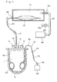
- Fig. 2 is a side cross-sectional view showing a separated component transferring apparatus which is not according to the present invention but useful for describing transfer of reparated component.
- the apparatus 30 is provided with a centrifugal container (inner cup) 40 in which connected bags of the multiple bag system is to be placed.
- This centrifugal container 40 is formed into a cylindrical configuration having a bottom and adapted to be removably attached to a centrifugal separator.
- the bottom 41 of this cup 40 is formed into a semispherical shape.
- the centrifugal container 40 is formed of a material having a rigidity of such an extent as not to be deformed easily even when it is centrifuged or even when the blood collecting bag 1 accommodated in the container 40 is pressed by the pushing means (described later).
- the material is formed of an acrylic resin such as hard polyvinyl chloride, polyethylene, polypropylene, polycarbonate, polymethylmethacrylate (PMMA), or the like; a metal such as stainless steel or aluminum; various glasses or ceramics; or appropriate combinations of any of these materials.
- the connected bags having the blood collecting bag in which blood is stored are placed, and then centrifuged.
- the connected bags are put into the centrifugal container 40 by stacking the respective bags 1, 10, 16 and 27 and by directing the upper portion of the respective bag, that is the side on which the opening portion is formed toward the upper opening portion side of the centrifugal container 40.
- the method of removably setting the centrifugal container 40 to the centrifugal separator is not particularly limited.
- the centrifugal container 40 may be constructed such that the container 40 is supported at opposite two portions of the upper annular edge thereof (not shown) so as to be rotatable with respect to the axis extending through the two supported portions.
- the separated component transferring apparatus 30 is provided with a pressing means for pressing the blood collecting bag 1 in which blood is contained.
- the pressing means is composed of an expansible and contractible cuff 50 to be interposed between the inner surface of the centrifugal container 40 and the outer surface of the blood collecting bag 1, and a fluid supplying means 51 for supplying a fluid such as air into the cuff 50 for expansion thereof.
- the cuff 50 is formed into an annular tubular shape so as to be able to push or press the outer circumferential surface of the blood collecting bag 1 roughly uniformly. As shown in Fig. 3, the cuff 50 is constituted so as to provide a central space under the contracted condition thereof into which the blood collecting bag 1 containing the blood can be passed therethrough.
- the cuff 50 is formed of a sheet material made of various rubbers (e.g., silicone rubber. etc.), various resins (e.g., soft polyvinyl chloride, polyethylene, polypropylene, etc.), cloth, and any appropriate combinations of these materials.
- various rubbers e.g., silicone rubber. etc.
- various resins e.g., soft polyvinyl chloride, polyethylene, polypropylene, etc.
- the dimensions of the cuff 50 are not limited to specific values. However, it is preferable to determine the width W of the cuff 50 within a range between 50 mm and 100 mm, in particular between 70 mm and 90 mm.
- the cuff 50 may be fixed to either the inner surface of the centrifugal container 40 or the outer surface of the blood collecting bag 1. Alternatively, the cuff 50 is simply interposed between the centrifugal container 40 and the blood collecting bag 1. Further, the shape of the cuff 50 is not limited only to the annular shape as shown. For instance, it is possible to arrange a pair of flat bags on the front and rear sides of the blood collecting bag 1, respectively.
- the fluid supplying means 51 is composed of an air feeding tube 52 communicating with the inner side of the cuff 50; an air supply source 55 such as air cylinder, air compressor, compressed gas cylinder, etc.; another air feeding tube 53 connected to the air supply source 55; a pair of male and female connectors 54 connected between the two air feeding tubes 52 and 53; and open and close valve 56 disposed midway of the air feeding tube 53 to control the air supplied into the cuff 50.
- the open and close valve 56 may be constructed into the type in which the air pressure supplied to the cuff 50 can be adjusted by adjusting the opening rate thereof.
- the fluid for expanding the cuff 50 is not limited to only air, and other gas or water can be used.
- the connector 54 is removed from the cuff 50 to contract the cuff 50.
- the blood collecting bag 1 in which blood is contained is placed in the centrifugal container 40, and the centrifugal container 40 accommodating the blood collecting bag 1 is then set to the centrifugal separator (not shown) for centrifugal separation. Therefore, the blood in the blood collecting bag 1 is separated into three layers i.e. a plasma layer, a buffy coat layer, and an erythrocyte layer in this order from the above.
- the centrifugal container 40 After the centrifugal separation, under the condition that the blood collecting bag 1 is kept placed in the centrifugal container 40, the centrifugal container 40 is removed from the centrifugal separator, and further fixed to a fixing means (not shown) such as a stand or a mounting base. In this state, since the blood collecting bag 1 is not removed from the centrifugal container 40, the interfaces between two of the respective separated components are not disturbed. In this case, it should be noted that in the case where all the connected bags in the double, triple, or quadruple bag system are placed in the centrifugal container 40 for centrifugal separation, the bag or bags other than the blood collecting bag 1 are removed from the centrifugal container 40.
- the plasma in the upper layer is collected from the separated components.
- the connecting member 15 of the upper portion of the blood collecting bag 1 is broken to allow the fluid communication and further the tube 26 is closed by a clamp or an electrically actuated solenoid pinch valve or the like.
- the connector 54 is connected.
- the air supply source 55 is actuated and the valve 56 is opened, to feed air into the cuff 50 through the air feeding tubes 52 and 53, so that the cuff 50 is expanded.
- the blood collecting bag 1 is pressed and thereby the inner pressure thereof increases. With this result, the upper plasma layer is discharged through the outlet 5, and further fed into the plasma bag 10 through the tubes 14, 21 and 23, respectively.
- the blood collection bag 1 is kept under the expanded condition, as already explained. Therefore, the lower components will not mixed with the plasma now being discharged and fed, thus improving the yield for the collection of the plasma.
- the discharging speed of the plasma from the blood collecting bag 1 is preferably set in the rate under which no eddy that is likely to disturb the interface between the respective separated components is caused in the blood-collecting bag 1 and the time required for the collection of the plasma can be shortened as much as possible.
- the control of the discharging speed of the plasma can be conducted, for example, by controlling the pressure of the actuating fluid to be supplied to the cuff 50.
- sucking means (not shown) together with the pressing means for pressing the blood collecting bag 1.
- the quantity of plasma discharged per unit time can be increased while keeping the high yield, it is possible to shorten the time required to collect the separated components.
- Fig. 5 is a cross-sectional view showing one example of the sucking means.
- the sucking means 90 shown in the drawing comprises a vacuum chamber 91, a vacuum pump 92, a pipe 93 connected between the vacuum chamber 91 and the vacuum pump 92.
- On the middle portion of the pipe 93 there is formed a branch pipe 94, on which a valve 95 is provided.
- the plasma bag 10 which is a container for collecting the separated plasma is adapted to be placed in the vacuum chamber 91.
- the tube 23 connected to the plasma bag 10 passes through a wall portion of the vacuum chamber 91 by means of a seal member. With this structure, the vacuum chamber 91 can be kept air-tight.
- valve 95 With valve 95 closed, when the vacuum pump 92 is actuated, the air in the vacuum chamber 91 is discharged through the pipe 93, and therefore the inner pressure of the vacuum chamber 91, that is, the atmosphere around the plasma bag 10 is reduced to be a negative pressure. Due to this reduced pressure, the plasma is sucked into the plasma bag 10. In this case, it is preferable to maintain the inner pressure of the vacuum chamber 91 to a constant value or within a predetermined value during the sucking operation.
- the adjustment of the inner pressure of the vacuum chamber 91 is made for example by on-off operation of the vacuum pump 92, open-close operation of the valve 95, or adjustment of the opening rate of the valve 95.
- the reduced inner pressure of the vacuum chamber 91 during the sucking operation is for example set to the rate between -0.133 bar (-100 mmHg) and -0.399 bar (-300 mmHg) (here, 0 mmHg is equal to the atmospheric pressure).
- sucking means it is possible to provide a roller pump provided on the midway of the tube 14 connected to the blood collecting bag 1.
- the roller pump is adapted to squeeze the tube 14 so as to transfer the liquid within the tube to the side of the plasma bag 10.
- the quantity of air to be sucked is set to such an extent that a rising in the inner pressure of the blood collecting bag 1 by the pressing means is not reduced markedly.
- the tube 21 is closed by a clamp or a solenoid pinch valve, while the tube 26 is opened.
- the intermediate buffy coat layer can be discharged.
- the buffy coat layer is fed into the buffy coat bag 27 through the tubes 14 and 26, respectively.
- the buffy coat bag 27 which is a container for collecting the buffy coat layer is placed inside the vacuum chamber 91 of the sucking means 90.
- an optical sensor 80 at the midway of the tube 14 to detect the fact that almost all the quantity of the plasma in the blood collecting bag 1 has been discharged.
- This optical sensor 80 is constituted by light emitting element and light receiving element which are disposed on the opposite sides of the tube 14.
- the transfer of the plasma to the plasma bag 10 is stopped by closing the tube 21 by clamping the midway of the tube 21 by a clamp or by actuating the solenoid pinch valve through the control performed by a micro computer (not shown). Thereafter, by opening the fluid path to the buffy coat bag 27, fluid communication is changed so as to allow the buffy coat is fed or transferred into the buffy coat bag 27. In this state, the actuating fluid from the fluid supply means 51 to the cuff 50 is supplied continuously, so that the buffy coat is being discharged from the blood collecting bag 1.
- the weight of the buffy coat bag 27 is kept monitored by a weight sensor such as a load cell (not shown).
- a weight sensor such as a load cell (not shown).
- the weight sensor detects the fact that the weight of the buffy coat stored in the buffy coat bag 27 reaches a predetermined value, the transfer of the buffy coat from the blood collecting bag 1 to the buffy coat bag 27 is stopped.
- the discharge of the buffy coat from the blood collecting bag 1 is stopped by stopping the supply of the actuating fluid from the fluid supply means 51 to the cuff 50 or closing the tube 14 or 26 with a clamp or the like.
- the supply of the actuating fluid is stopped by closing the valve 56 or stopping the operation of the air supply source 55.
- the apparatus is constituted such that the discharge of the blood component from the blood collecting bag 1 can be stopped or changed so as to direct toward a different bag in good timing based on the detected information by the optical sensor 80 or the weight sensor, the yield for the component is further improved.
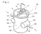
- Fig. 4 is a perspective view showing a separated component transferring apparatus according to the present invention.
- the centrifugal container 40 that is, the side portion 42 thereof is formed of a soft material to provide a soft material part 48.
- this soft material part 48 is pressed by a movable push member 57, the soft material part 48 is deformed so as to project in the inner direction of the centrifugal container 40.
- the movable push member 57 is composed of a movable piston 58 and a head 59 fixed to an end of the piston 58, and driving means (not shown) are provided for driving the movable push member 57.
- the pressing means of this embodiment is composed of a pair of opposing push members 57 and the driving means (not shown) for driving the push members 57 both roughly in the horizontal direction.
- the soft material part 48 of the centrifugal container 40 is pressed by the two heads 59 and then deformed in the inner direction of the centrifugal container 40.
- the blood collecting bag 1 placed in the centrifugal container 40 is also compressed, so that the plasma in the upper layer is discharged from the blood collecting bag 1.
- the pressing means is constructed such that one of the push members 57 is not movable and only the other push member 57 is movable so as to press the soft material part 48 of the centrifugal container 40.
- the soft material part 48 of the centrifugal container 40 is formed of a soft synthetic resin like a polyester such as soft polyvinyl chloride, polyethylene, polypropylene, polyethyleneterephtalate, or a combination of these materials. Further, the soft material part 48 can be formed at a bottom portion 41 of the centrifugal container 40, without being limited to only the side portion 42 thereof as described in the drawing.
- a portion excepting a frame portion 401, that is, a cylindrical portion thereof can be formed of the soft material as described above.
- any types of the pressing means such as rollers, fastening members, etc. can be used instead of the pair of the heads 59 as described above, as far as the soft material part 48 of the centrifugal container 40 can be deformed inwardly.
- the blood collecting bag 1 can be pressed from the front and rear side thereof, the interfaces between the respective component layers are kept more stationary when the separated component is being discharged, thus leading to improvement of the yield for the blood component.
- the driving means of this embodiment is formed from the mechanism which merely perform reciprocal motion, the mechanism can be constructed with simple structure.
- sucking means described with reference to Fig. 5 can also be applied to the apparatus according to the present invention.
- this invention can be applied to the case other than the transfer of the centrifugally separated blood component.
- this invention can be used for collecting or taking out a layer including the effective component of eupyrene cells from a bone marrow fluid, for instance.
- a quadruple bag system (four-connected bags) as shown in Fig. 1 was manufactured as follows: a blood collecting bag (400 ml in volume), a PC bag (60 ml in volume), a plasma bag (300 ml in volume) and a buffy coat bag (60 ml in volume) are all manufactured by use of a soft polyvinyl chloride sheet with a thickness of 0. 39 mm. Further, these bags are connected through soft polyvinyl chloride tubes as shown in Fig. 1.
- a centrifugal container 40 as shown in Fig. 2 was manufactured by use of polypropylene.
- the wall thickness of the container 40 was 2. 5 mm, the inner diameter thereof was 95 mm, and the maximum depth thereof was 130 mm.
- the annular cuff was placed on an inner surface of the centrifugal container 40 at a position 30 mm away from the bottom of the container 40, and further connected to an air supplying source (i.e. air compressor) through an air feeding tube.
- air supplying source i.e. air compressor
- a whole blood was collected in the blood collecting bag of the above-mentioned connected bags, and the blood collecting bag was placed in the centrifugal container under the condition that the annular cuff was contracted together with other bags. Then, the centrifugal container was set to a centrifugal separator (MODEL: DPR-6000 MODEL made by IEC Corp.), and centrifuged under 420rpm for 5 minutes.
- a centrifugal separator MODEL: DPR-6000 MODEL made by IEC Corp.
- the centrifugal container 40 was removed from the centrifugal separator, and further the bags other than the blood collecting bag were also removed from the centrifugal container 40.
- the connecting member 15 was then broken to effect the fluid communication therethrough, and further the tube 26 is closed by a clamp.
- the compressor was actuated, and compressed air of 0. 6 Kg/cm2 is fed into the annular cuff to expand the annular cuff gradually, so that the blood collecting bag in the centrifugal container was pressed to discharge the plasma in the upper layer through the tube 14. The discharged plasma was then transferred and collected into the plasma bag 10.
- the blood collecting bag accommodated in the centrifugal container was pressed in the same way as in Experiment 1, while the plasma bag 10 was placed in a pressure reducing chamber kept at a vacuum of - 0.239 bar (- 180 mmHg), to suck the plasma in the upper layer in the blood collecting bag in order to transfer and collect it into the plasma bag 10 through the tube 14.
- the connected bags were removed from the centrifugal container 40, and only the blood collecting bag was set between a pair of plates of a separator stand by hanging a small hole formed in the blood collecting bag on a hook of the separator stand. Then, the blood collecting bag was sandwiched between the two plates of the separator stand for pressurization, to discharge the plasma in the upper layer and transfer and collect it to the plasma bag 10.
- the yield for plasma collection is high in Experiments 1 and 2, as compared with Comparative Experiment.
- the time required to collect plasma can be shortened.
- the above-mentioned method is not appropriate due to the following reasons. That is to say, where the above-mentioned method is adopted alone, the inner pressure of the blood collecting bag is reduced into a vacuum pressure. For this reason, when the plasma layer is being discharged with the advance of pump suction, the two opposing inner surfaces of the bag are brought into contact with each other in particular at the upper portion of the bag. In addition, since gaps (channels) are produced between the inner surfaces of the bag so as to extendfrom the upper end discharge port 5 (outlet) of the bag to the vicinity of the fused edge portions of the bag, the separated component lower than the plasma layer, in particular the lowermost erythrocyte layer is sucked upwardly along the produced gaps. As a result, the erythrocyte is likely to be mixed with the plasma, thus causing another problem in that the yield for plasma collection is lowered.
- the quantity of liquid within the blood collecting bag is further reduced, so that the two opposing inner surfaces of the bag are brought into further tight contact with each other. Therefore, a great quantity of erythrocyte is likely to be discharged through the gaps formed between the inner surfaces of the bag. In other words, the collection of the buffy coat layer must be stopped before the erythrocyte is mixed. This means that a quantity of the buffy coat layer remains within the blood collecting bag. As a result, it is difficult to separate the buffy coat layer from the erythrocyte layer effectively.
- the separated component transferring apparatus and method according to the present invention it is possible to improve the yield for the blood component obtained by the centrifugal separation, and further to reduce the time and labor required for separation.
Landscapes
- Health & Medical Sciences (AREA)
- Heart & Thoracic Surgery (AREA)
- Life Sciences & Earth Sciences (AREA)
- Animal Behavior & Ethology (AREA)
- Engineering & Computer Science (AREA)
- Anesthesiology (AREA)
- Biomedical Technology (AREA)
- Hematology (AREA)
- Pathology (AREA)
- Vascular Medicine (AREA)
- General Health & Medical Sciences (AREA)
- Public Health (AREA)
- Veterinary Medicine (AREA)
- External Artificial Organs (AREA)
- Medical Preparation Storing Or Oral Administration Devices (AREA)
- Centrifugal Separators (AREA)
Claims (7)
- Vorrichtung (32) zum Übertragen eines getrennten Bestandteils in einer Flüssigkeit, welche in einem flexiblen Beutel (1) in luftdichtem Zustand enthalten ist, umfassend:dadurch gekennzeichnet, daß der Zentrifugalbehälter (40) einen Rahmenabschnitt (401) und einen Abschnitt (48) aus weichem Material umfaßt;einen verformbaren Zentrifugalbehälter (40) zum lösbaren Aufnehmen des flexiblen Beutels (1) darin;eine außen an dem Zentrifugalbehälter (40) vorgesehene Drückeinrichtung zum Drücken des in dem Zentrifugalbehälter (40) aufgenommenen flexiblen Beutels (1), so daß der Innendruck des flexiblen Beutel (1) erhöht wird, während der Beutel (1) aus dem luftdichten Zustand freigegeben wird, so daß ein vorbestimmter getrennter Bestandteil aus dem Beutel (1) abgegeben werden kann,
wobei die Drückeinrichtung ein Paar gegenüberliegender Druckelemente (57) umfaßt, wobei mindestens eines davon hin zu dem anderen durch eine Reziprokbewegungs-Antriebsvorrichtung bewegbar ist, wobei die Druckelemente (57) angepaßt sind, den Abschnitt aus weichem Material des Zentrifugalbehälters (40) zu drücken, welcher dadurch verformt wird, so daß dieser in die Innenrichtung bezüglich des Zentrifugalbehälters vorsteht, wodurch der getrennte Bestandteil der in dem flexiblen Beutel enthaltenen Flüssigkeit abgegeben wird. - Vorrichtung nach Anspruch 1 , wobei jedes der Druckelemente eine Rolle zum Drücken des Abschnitts aus weichem Material umfaßt.
- Vorrichtung nach einem der Ansprüche 1 bis 2, wobei die Vorrichtung ferner eine Saugeinrichtung (90) zum Saugen des getrennten Bestandteils in dem Beutel (1) umfaßt.
- Vorrichtung nach Anspruch 3, welche ferner einen Behälter (10) zum Aufnehmen des getrennten Bestandteils umfaßt, wobei die Saugeinrichtung (90) eine Einrichtung zum Verringern des Drucks einer Atmosphäre umfaßt, in welcher der Behälter (10) zum Aufnehmen des getrennten Bestandteils angeordnet ist.
- Verfahren zum Übertragen eines getrennten Bestandteils in einer in einem flexiblen Beutel (1) in luftdichtem Zustand enthaltenen Flüssigkeit, folgende Schritte umfassend:Aufnehmen des flexiblen Beutels, in welchem die Flüssigkeit in luftdichtem Zustand enthalten ist, in einem Zentrifugalbehälter (40), welcher abnehmbar an einer Trennzentrifuge angebracht ist, wobei der Zentrifugalbehälter einen Abschnitt aus weichem Material umfaßt, welcher in mindestens einem Abschnitt davon ausgebildet ist;Zentrifugieren des in dem Zentrifugalbehälter (40) aufgenommenen flexiblen Beutels (1) durch die Trennzentrifuge, so daß die Flüssigkeit in dem flexiblen Beutel (1) in die Bestandteile davon getrennt wird;Entfernen des Zentrifugalbehälters (40) von der Trennzentrifuge zusammen mit dem darin enthaltenen flexiblen Beutel und anschließendes Befestigen des Zentrifugalbehälters an einer Befestigungseinrichtung; undDrücken des Abschnitts aus weichem Material des Zentrifugalbehälters (40) ausgehend von dem Äußeren des Zentrifugalbehälters (40) unter Verwendung eines beweglichen Druckelements (57), welches außen an dem Behälter (40) vorgesehen ist, zum Drücken des Abschnitts aus weichem Material des Zentrifugalbehälters (40), so daß der Innendruck des Beutels (1) erhöht wird, während der luftdichte Zustand freigegeben wird, wodurch ein vorbestimmter Bestandteil in der Flüssigkeit entnommen wird, welcher durch die Zentrifugierung außerhalb des flexiblen Beutels (1) getrennt wurde.
- Verfahren nach Anspruch 5, ferner umfassend den Schritt des Saugens des getrennten Bestandteils in dem flexiblen Beutel (1), während der flexible Beutel (1) gedrückt wird.
- Verfahren nach Anspruch 5, ferner umfassend den Schritt des Saugens des getrennten Bestandteils in dem flexiblen Beutel (1) durch Verringern des Drucks einer Atmosphäre, in welcher ein Behälter (10) zum Aufnehmen eines getrennten Bestandteils angeordnet wird, während der flexible Beutel (1) gedrückt wird.
Applications Claiming Priority (3)
| Application Number | Priority Date | Filing Date | Title |
|---|---|---|---|
| JP197898/92 | 1992-06-30 | ||
| JP19789892A JP3231086B2 (ja) | 1992-06-30 | 1992-06-30 | 液体分離装置 |
| JP19789892 | 1992-06-30 |
Publications (2)
| Publication Number | Publication Date |
|---|---|
| EP0578086A1 EP0578086A1 (de) | 1994-01-12 |
| EP0578086B1 true EP0578086B1 (de) | 2001-08-16 |
Family
ID=16382120
Family Applications (1)
| Application Number | Title | Priority Date | Filing Date |
|---|---|---|---|
| EP93110259A Expired - Lifetime EP0578086B1 (de) | 1992-06-30 | 1993-06-28 | Gerät und Methode zur Transferierung einer in einer Flüssigkeit abgetrennten Komponente |
Country Status (5)
| Country | Link |
|---|---|
| US (1) | US5632906A (de) |
| EP (1) | EP0578086B1 (de) |
| JP (1) | JP3231086B2 (de) |
| CA (1) | CA2099430C (de) |
| DE (1) | DE69330585T2 (de) |
Cited By (13)
| Publication number | Priority date | Publication date | Assignee | Title |
|---|---|---|---|---|
| US7052606B2 (en) | 2001-12-10 | 2006-05-30 | Gambro, Inc. | Methods and apparatus for leukoreduction of red blood cells |
| US7279107B2 (en) | 2002-04-16 | 2007-10-09 | Gambro, Inc. | Blood component processing system, apparatus, and method |
| US7651474B2 (en) | 1999-10-01 | 2010-01-26 | Caridianbct, Inc. | Method and apparatus for leukoreduction of red blood cells |
| US7807246B2 (en) | 2003-02-14 | 2010-10-05 | The Procter & Gamble Company | Dry paint transfer laminate |
| US8454548B2 (en) | 2008-04-14 | 2013-06-04 | Haemonetics Corporation | System and method for plasma reduced platelet collection |
| US8628489B2 (en) | 2008-04-14 | 2014-01-14 | Haemonetics Corporation | Three-line apheresis system and method |
| US8702637B2 (en) | 2008-04-14 | 2014-04-22 | Haemonetics Corporation | System and method for optimized apheresis draw and return |
| US8834402B2 (en) | 2009-03-12 | 2014-09-16 | Haemonetics Corporation | System and method for the re-anticoagulation of platelet rich plasma |
| US9028388B2 (en) | 2010-06-07 | 2015-05-12 | Terumo Bct, Inc. | Multi-unit blood processor with volume prediction |
| US9079194B2 (en) | 2010-07-19 | 2015-07-14 | Terumo Bct, Inc. | Centrifuge for processing blood and blood components |
| US9302042B2 (en) | 2010-12-30 | 2016-04-05 | Haemonetics Corporation | System and method for collecting platelets and anticipating plasma return |
| US9687598B2 (en) | 2010-05-27 | 2017-06-27 | Terumo Bct, Inc. | Multi-unit blood processor with temperature sensing |
| US9733805B2 (en) | 2012-06-26 | 2017-08-15 | Terumo Bct, Inc. | Generating procedures for entering data prior to separating a liquid into components |
Families Citing this family (85)
| Publication number | Priority date | Publication date | Assignee | Title |
|---|---|---|---|---|
| US5733253A (en) * | 1994-10-13 | 1998-03-31 | Transfusion Technologies Corporation | Fluid separation system |
| US7332125B2 (en) | 1994-10-13 | 2008-02-19 | Haemonetics Corporation | System and method for processing blood |
| US6632191B1 (en) | 1994-10-13 | 2003-10-14 | Haemonetics Corporation | System and method for separating blood components |
| US5651766A (en) * | 1995-06-07 | 1997-07-29 | Transfusion Technologies Corporation | Blood collection and separation system |
| DE4443577C2 (de) * | 1994-12-08 | 1997-08-28 | Heraeus Instr Gmbh | Vorrichtung für die Entnahme und die Aufbereitung von Blutkonserven |
| SE9700495D0 (sv) * | 1997-02-12 | 1997-02-12 | Omega Medicinteknik Ab | Metod och rundpåsesystem samt centrifug för behandling av blod |
| SE9701423D0 (sv) * | 1997-04-16 | 1997-04-16 | Omega Medicinteknik Ab | Behållarset och anordning för blodseparation |
| ES2243023T3 (es) * | 1998-05-19 | 2005-11-16 | Terumo Kabushiki Kaisha | Metodo de eliminacion de globulos blancos. |
| US6296602B1 (en) | 1999-03-17 | 2001-10-02 | Transfusion Technologies Corporation | Method for collecting platelets and other blood components from whole blood |
| SE516321C2 (sv) | 1999-05-31 | 2001-12-17 | Gambro Inc | Centrifug för behandling av blod och blodkomponenter |
| US6652475B1 (en) | 1999-07-07 | 2003-11-25 | Mission Medical, Inc. | Automated blood component separation system |
| AU734550B2 (en) * | 1999-09-02 | 2001-06-14 | Haemonetics Corporation | Blood processing system |
| SE517032C2 (sv) | 1999-10-26 | 2002-04-02 | Gambro Inc | Sätt och anordning för behandling av blod och blodkomponenter |
| US7011742B2 (en) * | 2001-09-14 | 2006-03-14 | Zymequest, Inc. | Blood product transfer system |
| US6554996B1 (en) | 2001-10-05 | 2003-04-29 | Bio-Microbics, Inc. | Wastewater treatment system |
| EP1476208B1 (de) | 2002-02-01 | 2011-10-05 | CaridianBCT, Inc. | System zur entnahme und aufbereitung von vollblut |
| WO2004032999A1 (en) * | 2002-10-09 | 2004-04-22 | Eczacibaşi - Baxter Hastane Ürünleri̇ A.Ş | A liquid component separator |
| US7207970B2 (en) * | 2003-06-27 | 2007-04-24 | Nipro Corporation | Displaceable-plug-containing filling/discharging port and medical container having the same |
| US7347932B2 (en) * | 2003-08-25 | 2008-03-25 | Gambro Bct, Inc. | Apparatus and method for separating a volume of composite liquid into at least two components |
| DE10355026B4 (de) * | 2003-11-25 | 2011-06-22 | Andreas Hettich GmbH & Co. KG, 78532 | Aufnahmebecher für Beutel zur Behandlung biologischer Flüssigkeiten durch Zentrifugation |
| US7264141B2 (en) * | 2004-02-19 | 2007-09-04 | Sanford, L.P. | Fluid dispenser with passive pressurization |
| CN100593438C (zh) * | 2004-02-20 | 2010-03-10 | 科安比司特公司 | 将一体积量的混合液体分离成至少两种成分的装置和方法 |
| US20070209708A1 (en) * | 2004-06-22 | 2007-09-13 | Gambro, Inc. | Bag Assembly for the Separation of a Composite Liquid and Method for Manufacturing it |
| WO2006029270A1 (en) * | 2004-09-07 | 2006-03-16 | Smith & Nephew, Inc. | Methods and devices for sterile field transfer |
| EP1833452A1 (de) * | 2004-11-23 | 2007-09-19 | Smith and Nephew, Inc. | Kompositionsmischer |
| EP2080531B1 (de) | 2004-12-28 | 2015-09-02 | Terumo BCT, Inc. | Vorrichtung und Verfahren zur Trennung eines Volumens von Vollblut in mindestens drei Komponenten |
| EP1925328B1 (de) * | 2005-06-22 | 2015-07-22 | Terumo BCT, Inc. | Beutelset zur Auftrennung einer Flüssigkeit aus mehreren Komponenten in einer Zentrifuge |
| WO2007001739A1 (en) | 2005-06-22 | 2007-01-04 | Gambro Bct, Inc. | Apparatus and method for separating discrete volumes of a composite liquid |
| WO2007024518A2 (en) * | 2005-08-22 | 2007-03-01 | Gambro Inc. | Apparatus and method for separating a composite liquid into at least two components |
| US8272255B2 (en) * | 2006-05-22 | 2012-09-25 | 3M Innovative Properties Company | System and method for preparing samples |
| WO2007143386A2 (en) * | 2006-06-07 | 2007-12-13 | Gambro Bct, Inc. | Apparatus and method for separating a composite liquid into at least two components |
| EP2206527B1 (de) * | 2006-09-06 | 2016-01-27 | Terumo BCT, Inc. | Vorrichtung und Verfahren zur Trennung einer Flüssigverbindung in mindestens zwei Komponenten |
| US8016736B2 (en) | 2006-10-20 | 2011-09-13 | Caridianbct Biotechnologies, Llc | Methods for washing a red blood cell component and for removing prions therefrom |
| JP5405313B2 (ja) * | 2006-12-20 | 2014-02-05 | テルモ ビーシーティー、インコーポレーテッド | 複合液体を少なくとも2つの成分に分離するための機器および方法 |
| US20080156728A1 (en) * | 2006-12-29 | 2008-07-03 | Bryan Blickhan | Biological fluid filtration systems and methods |
| EP2134386B1 (de) * | 2007-04-06 | 2018-12-26 | Fenwal, Inc. | Filtrationssysteme für biologische flüssigkeiten und verfahren |
| WO2008140561A1 (en) * | 2007-05-14 | 2008-11-20 | Caridianbct, Inc. | Apparatus and method for separating a composite liquid into at least two components |
| AT505433B1 (de) * | 2007-07-06 | 2009-10-15 | Technoclone Ges M B H | Plasmafiltration |
| WO2009017041A1 (ja) * | 2007-07-30 | 2009-02-05 | Jms Co., Ltd. | 血液成分分離収容装置 |
| CA2749771C (en) * | 2008-01-28 | 2018-05-01 | Milux Holding S.A. | A drainage device comprising an active filter |
| US20090272701A1 (en) * | 2008-05-02 | 2009-11-05 | Caridianbct, Inc. | Centrifuge Apparatus and Method for Selectively Reducing Forces on a Biologic Fluid |
| CN104147815B (zh) * | 2008-07-29 | 2016-04-06 | 山崎明彦 | 处理装置及处理袋 |
| WO2010014330A2 (en) * | 2008-07-31 | 2010-02-04 | Caridianbct, Inc. | Method and apparatus for determining the yield of at least one component |
| US8721617B2 (en) | 2009-02-04 | 2014-05-13 | Jms Co., Ltd. | Liquid component collecting device |
| US8875893B2 (en) * | 2010-02-05 | 2014-11-04 | Fenwal, Inc. | Medical containers for use in blood collection and processing and medical systems, methods and apparatus for use in blood collection and processing |
| US8944983B2 (en) | 2010-06-17 | 2015-02-03 | Terumo Bct, Inc. | Multi-unit blood processor with isolated valves for radio frequency sealing |
| US8808978B2 (en) | 2010-11-05 | 2014-08-19 | Haemonetics Corporation | System and method for automated platelet wash |
| US9376654B2 (en) | 2011-03-03 | 2016-06-28 | Meissner Filtration Products, Inc. | Biocontainer |
| US11386993B2 (en) | 2011-05-18 | 2022-07-12 | Fenwal, Inc. | Plasma collection with remote programming |
| US8535241B2 (en) | 2011-10-13 | 2013-09-17 | Magnolia Medical Technologies, Inc. | Fluid diversion mechanism for bodily-fluid sampling |
| US9022951B2 (en) | 2012-05-30 | 2015-05-05 | Magnolia Medical Technologies, Inc. | Fluid diversion mechanism for bodily-fluid sampling |
| US9060724B2 (en) | 2012-05-30 | 2015-06-23 | Magnolia Medical Technologies, Inc. | Fluid diversion mechanism for bodily-fluid sampling |
| WO2014022275A1 (en) | 2012-08-01 | 2014-02-06 | Magnolia Medical Technologies, Inc. | Fluid diversion mechanism for bodily-fluid sampling |
| EP3906952A1 (de) | 2012-10-11 | 2021-11-10 | Magnolia Medical Technologies, Inc. | Systeme und verfahren zur abgabe einer flüssigkeit an einen patienten mit reduzierter kontamination |
| CA2931983C (en) | 2012-11-30 | 2021-12-07 | Magnolia Medical Technologies, Inc. | Syringe based fluid diversion mechanism for bodily-fluid sampling |
| IL303591B2 (en) | 2012-12-04 | 2025-11-01 | Magnolia Medical Technologies Inc | Sterile bodily-fluid collection device and methods |
| US10772548B2 (en) | 2012-12-04 | 2020-09-15 | Magnolia Medical Technologies, Inc. | Sterile bodily-fluid collection device and methods |
| CN105636571B (zh) * | 2013-09-25 | 2019-05-21 | 托朗塞爾股份有限公司 | 血液成分分离用装置 |
| FR3015902B1 (fr) | 2013-12-26 | 2017-03-03 | Maco Pharma Sa | Procede pour extraire au moins un premier et un deuxieme composant sanguin contenus dans une poche primaire d'un systeme a poches |
| CA2937486A1 (en) | 2014-01-20 | 2015-07-23 | Halcyon Biomedical, Incorporated | Passive separation of whole blood |
| USD734487S1 (en) * | 2014-01-24 | 2015-07-14 | Terumo Bct, Inc. | Connector for a centrifuge balance bag |
| USD734488S1 (en) * | 2014-01-24 | 2015-07-14 | Terumo Bct, Inc. | Combined centrifuge balance bag and connector |
| US9796166B2 (en) | 2014-03-24 | 2017-10-24 | Fenwal, Inc. | Flexible biological fluid filters |
| US10159778B2 (en) | 2014-03-24 | 2018-12-25 | Fenwal, Inc. | Biological fluid filters having flexible walls and methods for making such filters |
| US9968738B2 (en) | 2014-03-24 | 2018-05-15 | Fenwal, Inc. | Biological fluid filters with molded frame and methods for making such filters |
| US10376627B2 (en) | 2014-03-24 | 2019-08-13 | Fenwal, Inc. | Flexible biological fluid filters |
| US9782707B2 (en) | 2014-03-24 | 2017-10-10 | Fenwal, Inc. | Biological fluid filters having flexible walls and methods for making such filters |
| USD740958S1 (en) * | 2014-10-10 | 2015-10-13 | Terumo Bct, Inc. | Centrifuge counter balance bag |
| EP3769681B1 (de) | 2015-06-12 | 2022-03-02 | Magnolia Medical Technologies, Inc. | Vorrichtung zur probenahme und fluidtransfer von körperflüssigkeiten |
| DE202015103285U1 (de) * | 2015-06-23 | 2016-09-26 | Dr. Herfeld Gmbh & Co. Kg | Mischcontainer sowie Entleerstation für einen solchen Mischcontainer |
| US10010282B2 (en) | 2015-07-24 | 2018-07-03 | Kurin, Inc. | Blood sample optimization system and blood contaminant sequestration device and method |
| EP3344213B1 (de) | 2015-09-03 | 2020-04-22 | Magnolia Medical Technologies, Inc. | System zum aufrechterhalten der sterilität eines probenbehälters |
| US10827964B2 (en) | 2017-02-10 | 2020-11-10 | Kurin, Inc. | Blood contaminant sequestration device with one-way air valve and air-permeable blood barrier with closure mechanism |
| US10792416B2 (en) | 2017-05-30 | 2020-10-06 | Haemonetics Corporation | System and method for collecting plasma |
| US10758652B2 (en) | 2017-05-30 | 2020-09-01 | Haemonetics Corporation | System and method for collecting plasma |
| US20180353117A1 (en) | 2017-06-09 | 2018-12-13 | Magnolia Medical Technologies, Inc. | Fluid control devices and methods of using the same |
| CN116250868A (zh) | 2017-09-12 | 2023-06-13 | 木兰医药技术股份有限公司 | 流体控制装置及其使用方法 |
| CN115553822A (zh) | 2017-12-07 | 2023-01-03 | 木兰医药技术股份有限公司 | 流体控制装置及其使用方法 |
| DE102018001675A1 (de) * | 2018-03-02 | 2019-09-05 | Thermo Electron Led Gmbh | Einweg-Zentrifugenbehälter zum Auftrennen biologischer Suspensionen sowie Verfahren zu deren Anwendung |
| HUE056564T2 (hu) | 2018-05-21 | 2022-02-28 | Fenwal Inc | Rendszerek plazmagyûjtõ térfogatok optimalizálására |
| US12033750B2 (en) | 2018-05-21 | 2024-07-09 | Fenwal, Inc. | Plasma collection |
| US11412967B2 (en) | 2018-05-21 | 2022-08-16 | Fenwal, Inc. | Systems and methods for plasma collection |
| US11786155B2 (en) | 2019-02-08 | 2023-10-17 | Magnolia Medical Technologies, Inc. | Devices and methods for bodily fluid collection and distribution |
| CN113784793B (zh) | 2019-03-11 | 2023-09-19 | 木兰医药技术股份有限公司 | 流体控制装置及其使用方法 |
| IL322058A (en) | 2019-04-01 | 2025-09-01 | Kurin Inc | Device and system for optimizing sampling of non-aerated liquids |
Family Cites Families (13)
| Publication number | Priority date | Publication date | Assignee | Title |
|---|---|---|---|---|
| US1872837A (en) * | 1931-07-13 | 1932-08-23 | Joseph J Smith | Dispensing device |
| US3151616A (en) * | 1962-07-25 | 1964-10-06 | Paul M Selfon | Automatic transfusion apparatus |
| US4303193A (en) * | 1979-01-22 | 1981-12-01 | Haemonetics Corporation | Apparatus for separating blood into components thereof |
| EP0026417B1 (de) * | 1979-09-22 | 1983-12-14 | Firma Andreas Hettich | Zentrifuge mit Blutbeutelsystem zur Trennung von Blutkomponenten |
| ATE16350T1 (de) * | 1980-05-20 | 1985-11-15 | Haemonetics Corp | Fluessigkeitsabsaugapparat und flexibler beutel zur aufnahme von fluessigkeit, der zur verwendung in einem solchen apparat geeignet ist. |
| US4322298A (en) * | 1981-06-01 | 1982-03-30 | Advanced Blood Component Technology, Inc. | Centrifugal cell separator, and method of use thereof |
| US4439177A (en) * | 1981-10-26 | 1984-03-27 | Beckman Instruments, Inc. | Rotor bucket liner |
| US4539005A (en) * | 1983-10-24 | 1985-09-03 | Greenblatt Gordon M | Blood infusion apparatus and method |
| DE3417892A1 (de) * | 1984-05-14 | 1985-11-14 | Npbi Nederlands Produktielaboratorium Voor Bloedtransfusieapparatuur En Infusievloeistoffen B.V., Emmer-Compascuum | Vorrichtung zum entfernen einer blutplasmaschicht und einer buffycoatschicht aus einem flexiblen beutel mit blutfuellung |
| AU611656B2 (en) * | 1986-11-10 | 1991-06-20 | Takao Iwasa | Blood separator |
| US4976851A (en) * | 1988-06-06 | 1990-12-11 | Terumo Kabushiki Kaisha | Liquid separator |
| JP2547636B2 (ja) * | 1989-07-14 | 1996-10-23 | テルモ株式会社 | 液体分離装置 |
| SE9002255D0 (sv) * | 1990-06-26 | 1990-06-26 | Eric Westberg | Metod och anordning vid framstaellning av blod |
-
1992
- 1992-06-30 JP JP19789892A patent/JP3231086B2/ja not_active Expired - Lifetime
-
1993
- 1993-06-28 EP EP93110259A patent/EP0578086B1/de not_active Expired - Lifetime
- 1993-06-28 DE DE69330585T patent/DE69330585T2/de not_active Expired - Lifetime
- 1993-06-29 US US08/083,297 patent/US5632906A/en not_active Expired - Lifetime
- 1993-06-30 CA CA002099430A patent/CA2099430C/en not_active Expired - Lifetime
Cited By (19)
| Publication number | Priority date | Publication date | Assignee | Title |
|---|---|---|---|---|
| US7651474B2 (en) | 1999-10-01 | 2010-01-26 | Caridianbct, Inc. | Method and apparatus for leukoreduction of red blood cells |
| US7052606B2 (en) | 2001-12-10 | 2006-05-30 | Gambro, Inc. | Methods and apparatus for leukoreduction of red blood cells |
| US7682329B2 (en) | 2001-12-10 | 2010-03-23 | Caridianbct, Inc. | Methods and apparatus for leukoreduction of red blood cells |
| US7279107B2 (en) | 2002-04-16 | 2007-10-09 | Gambro, Inc. | Blood component processing system, apparatus, and method |
| US7497944B2 (en) | 2002-04-16 | 2009-03-03 | Caridianbct, Inc. | Blood component processing system, apparatus, and method |
| US7708889B2 (en) | 2002-04-16 | 2010-05-04 | Caridianbct, Inc. | Blood component processing system method |
| US7807246B2 (en) | 2003-02-14 | 2010-10-05 | The Procter & Gamble Company | Dry paint transfer laminate |
| US8628489B2 (en) | 2008-04-14 | 2014-01-14 | Haemonetics Corporation | Three-line apheresis system and method |
| US8454548B2 (en) | 2008-04-14 | 2013-06-04 | Haemonetics Corporation | System and method for plasma reduced platelet collection |
| US8702637B2 (en) | 2008-04-14 | 2014-04-22 | Haemonetics Corporation | System and method for optimized apheresis draw and return |
| US8834402B2 (en) | 2009-03-12 | 2014-09-16 | Haemonetics Corporation | System and method for the re-anticoagulation of platelet rich plasma |
| US9248227B2 (en) | 2009-03-12 | 2016-02-02 | Haemonetics Corporation | System and method for the re-anticoagulation of platelet rich plasma |
| US9687598B2 (en) | 2010-05-27 | 2017-06-27 | Terumo Bct, Inc. | Multi-unit blood processor with temperature sensing |
| US10226567B2 (en) | 2010-05-27 | 2019-03-12 | Terumo Bct, Inc. | Multi-unit blood processor with temperature sensing |
| US9028388B2 (en) | 2010-06-07 | 2015-05-12 | Terumo Bct, Inc. | Multi-unit blood processor with volume prediction |
| US9849222B2 (en) | 2010-06-07 | 2017-12-26 | Terumo Bct, Inc. | Multi-unit blood processor with volume prediction |
| US9079194B2 (en) | 2010-07-19 | 2015-07-14 | Terumo Bct, Inc. | Centrifuge for processing blood and blood components |
| US9302042B2 (en) | 2010-12-30 | 2016-04-05 | Haemonetics Corporation | System and method for collecting platelets and anticipating plasma return |
| US9733805B2 (en) | 2012-06-26 | 2017-08-15 | Terumo Bct, Inc. | Generating procedures for entering data prior to separating a liquid into components |
Also Published As
| Publication number | Publication date |
|---|---|
| CA2099430C (en) | 1999-08-24 |
| JP3231086B2 (ja) | 2001-11-19 |
| CA2099430A1 (en) | 1993-12-31 |
| US5632906A (en) | 1997-05-27 |
| JPH0614992A (ja) | 1994-01-25 |
| DE69330585T2 (de) | 2002-06-13 |
| DE69330585D1 (de) | 2001-09-20 |
| EP0578086A1 (de) | 1994-01-12 |
Similar Documents
| Publication | Publication Date | Title |
|---|---|---|
| US5632906A (en) | Apparatus and method for transferring separated component in liquid from a flexible bag in a centrifugal container | |
| US8876683B2 (en) | Automated system and method for blood components separation and processing | |
| FI84404B (fi) | Foerfarande och anordning foer att separera serum/plasma fraon blod. | |
| US7004727B2 (en) | Blood component processing systems and methods using fluid-actuated pumping elements that are integrity tested prior to use | |
| EP1554026B1 (de) | Erythrozytenverarbeitungssysteme und Verfahren zur Steuerung des Erythrozytenhämatokrits | |
| EP0484751B1 (de) | Trennungssystem im Boden von Blutbeuteln | |
| AU2003282971B2 (en) | Blood processing systems and methods for collecting plasma free or essentially free of cellular blood components | |
| US6860846B2 (en) | Blood processing systems and methods with umbilicus-driven blood processing chambers | |
| JP2548029B2 (ja) | 液体分離の為の装置 | |
| JP2004144080A (ja) | 自己装填式蠕動ポンプチューブカセット | |
| JP7106557B2 (ja) | 血液成分採取用カセット及びその製造方法 | |
| US11590268B2 (en) | Blood component collection cassette and manufacturing method of the same | |
| CN109922764B (zh) | 无菌的文丘里吸出 | |
| US6878105B2 (en) | Red blood cell processing systems and methods with deliberate under spill of red blood cells | |
| JPH09108333A (ja) | バッグ加圧装置 | |
| US20040079687A1 (en) | Multifunctional optical sensing assembly | |
| EP1663800B1 (de) | Presse zur Entfernung von Überstand aus einem flexiblen Behälter | |
| EP3939631A1 (de) | Blutbeutelsystem | |
| JP4346201B2 (ja) | 血液成分採取方法 | |
| US20240091419A1 (en) | Disposable Set | |
| JPH0780058A (ja) | バッグ連結体および成分の分離、移送方法 | |
| WO2004037375A1 (en) | Multifunctional optical sensing assembly | |
| HK1027048A (en) | Blood evacuating system and method of use thereof |
Legal Events
| Date | Code | Title | Description |
|---|---|---|---|
| PUAI | Public reference made under article 153(3) epc to a published international application that has entered the european phase |
Free format text: ORIGINAL CODE: 0009012 |
|
| AK | Designated contracting states |
Kind code of ref document: A1 Designated state(s): BE DE FR GB IT NL SE |
|
| 17P | Request for examination filed |
Effective date: 19940119 |
|
| 17Q | First examination report despatched |
Effective date: 19950627 |
|
| GRAG | Despatch of communication of intention to grant |
Free format text: ORIGINAL CODE: EPIDOS AGRA |
|
| GRAG | Despatch of communication of intention to grant |
Free format text: ORIGINAL CODE: EPIDOS AGRA |
|
| GRAG | Despatch of communication of intention to grant |
Free format text: ORIGINAL CODE: EPIDOS AGRA |
|
| GRAH | Despatch of communication of intention to grant a patent |
Free format text: ORIGINAL CODE: EPIDOS IGRA |
|
| GRAH | Despatch of communication of intention to grant a patent |
Free format text: ORIGINAL CODE: EPIDOS IGRA |
|
| GRAA | (expected) grant |
Free format text: ORIGINAL CODE: 0009210 |
|
| AK | Designated contracting states |
Kind code of ref document: B1 Designated state(s): BE DE FR GB IT NL SE |
|
| PG25 | Lapsed in a contracting state [announced via postgrant information from national office to epo] |
Ref country code: NL Free format text: LAPSE BECAUSE OF FAILURE TO SUBMIT A TRANSLATION OF THE DESCRIPTION OR TO PAY THE FEE WITHIN THE PRESCRIBED TIME-LIMIT Effective date: 20010816 Ref country code: BE Free format text: LAPSE BECAUSE OF FAILURE TO SUBMIT A TRANSLATION OF THE DESCRIPTION OR TO PAY THE FEE WITHIN THE PRESCRIBED TIME-LIMIT Effective date: 20010816 |
|
| REF | Corresponds to: |
Ref document number: 69330585 Country of ref document: DE Date of ref document: 20010920 |
|
| ET | Fr: translation filed | ||
| PG25 | Lapsed in a contracting state [announced via postgrant information from national office to epo] |
Ref country code: SE Free format text: LAPSE BECAUSE OF FAILURE TO SUBMIT A TRANSLATION OF THE DESCRIPTION OR TO PAY THE FEE WITHIN THE PRESCRIBED TIME-LIMIT Effective date: 20011116 |
|
| REG | Reference to a national code |
Ref country code: GB Ref legal event code: IF02 |
|
| NLV1 | Nl: lapsed or annulled due to failure to fulfill the requirements of art. 29p and 29m of the patents act | ||
| PLBE | No opposition filed within time limit |
Free format text: ORIGINAL CODE: 0009261 |
|
| STAA | Information on the status of an ep patent application or granted ep patent |
Free format text: STATUS: NO OPPOSITION FILED WITHIN TIME LIMIT |
|
| PG25 | Lapsed in a contracting state [announced via postgrant information from national office to epo] |
Ref country code: GB Free format text: LAPSE BECAUSE OF NON-PAYMENT OF DUE FEES Effective date: 20020628 |
|
| 26N | No opposition filed | ||
| GBPC | Gb: european patent ceased through non-payment of renewal fee |
Effective date: 20020628 |
|
| PGFP | Annual fee paid to national office [announced via postgrant information from national office to epo] |
Ref country code: DE Payment date: 20120620 Year of fee payment: 20 |
|
| PGFP | Annual fee paid to national office [announced via postgrant information from national office to epo] |
Ref country code: FR Payment date: 20120619 Year of fee payment: 20 |
|
| PGFP | Annual fee paid to national office [announced via postgrant information from national office to epo] |
Ref country code: IT Payment date: 20120621 Year of fee payment: 20 |
|
| REG | Reference to a national code |
Ref country code: DE Ref legal event code: R071 Ref document number: 69330585 Country of ref document: DE |
|
| PG25 | Lapsed in a contracting state [announced via postgrant information from national office to epo] |
Ref country code: DE Free format text: LAPSE BECAUSE OF EXPIRATION OF PROTECTION Effective date: 20130629 |