EP0577597B1 - Bilderzeugungsystem mit einem zwischenubertragungselement - Google Patents
Bilderzeugungsystem mit einem zwischenubertragungselement Download PDFInfo
- Publication number
- EP0577597B1 EP0577597B1 EP91907895A EP91907895A EP0577597B1 EP 0577597 B1 EP0577597 B1 EP 0577597B1 EP 91907895 A EP91907895 A EP 91907895A EP 91907895 A EP91907895 A EP 91907895A EP 0577597 B1 EP0577597 B1 EP 0577597B1
- Authority
- EP
- European Patent Office
- Prior art keywords
- intermediate transfer
- transfer member
- image
- imaging apparatus
- toner
- Prior art date
- Legal status (The legal status is an assumption and is not a legal conclusion. Google has not performed a legal analysis and makes no representation as to the accuracy of the status listed.)
- Expired - Lifetime
Links
- 238000003384 imaging method Methods 0.000 title claims abstract description 23
- 239000000758 substrate Substances 0.000 claims abstract description 60
- 238000007639 printing Methods 0.000 claims abstract description 7
- 239000007788 liquid Substances 0.000 claims description 44
- 238000010438 heat treatment Methods 0.000 claims description 33
- 239000002245 particle Substances 0.000 claims description 21
- 108091008695 photoreceptors Proteins 0.000 description 57
- 238000001816 cooling Methods 0.000 description 9
- 239000000203 mixture Substances 0.000 description 9
- 238000004140 cleaning Methods 0.000 description 7
- 239000000843 powder Substances 0.000 description 7
- 239000000463 material Substances 0.000 description 6
- 239000003086 colorant Substances 0.000 description 5
- 238000000034 method Methods 0.000 description 5
- 239000007787 solid Substances 0.000 description 5
- 238000002156 mixing Methods 0.000 description 4
- 239000000049 pigment Substances 0.000 description 4
- 239000012453 solvate Substances 0.000 description 4
- 238000000227 grinding Methods 0.000 description 3
- 229920002635 polyurethane Polymers 0.000 description 3
- 239000004814 polyurethane Substances 0.000 description 3
- 238000000926 separation method Methods 0.000 description 3
- 229910000975 Carbon steel Inorganic materials 0.000 description 2
- 229920003345 Elvax® Polymers 0.000 description 2
- MCMNRKCIXSYSNV-UHFFFAOYSA-N Zirconium dioxide Chemical compound O=[Zr]=O MCMNRKCIXSYSNV-UHFFFAOYSA-N 0.000 description 2
- 239000010962 carbon steel Substances 0.000 description 2
- 239000011248 coating agent Substances 0.000 description 2
- 238000000576 coating method Methods 0.000 description 2
- 239000002131 composite material Substances 0.000 description 2
- 239000012141 concentrate Substances 0.000 description 2
- 238000001962 electrophoresis Methods 0.000 description 2
- 238000002360 preparation method Methods 0.000 description 2
- 238000007614 solvation Methods 0.000 description 2
- 239000004698 Polyethylene Substances 0.000 description 1
- BUGBHKTXTAQXES-UHFFFAOYSA-N Selenium Chemical compound [Se] BUGBHKTXTAQXES-UHFFFAOYSA-N 0.000 description 1
- 229910000831 Steel Inorganic materials 0.000 description 1
- NIXOWILDQLNWCW-UHFFFAOYSA-N acrylic acid group Chemical group C(C=C)(=O)O NIXOWILDQLNWCW-UHFFFAOYSA-N 0.000 description 1
- AZDRQVAHHNSJOQ-UHFFFAOYSA-N alumane Chemical group [AlH3] AZDRQVAHHNSJOQ-UHFFFAOYSA-N 0.000 description 1
- CEGOLXSVJUTHNZ-UHFFFAOYSA-K aluminium tristearate Chemical compound [Al+3].CCCCCCCCCCCCCCCCCC([O-])=O.CCCCCCCCCCCCCCCCCC([O-])=O.CCCCCCCCCCCCCCCCCC([O-])=O CEGOLXSVJUTHNZ-UHFFFAOYSA-K 0.000 description 1
- 229940063655 aluminum stearate Drugs 0.000 description 1
- 239000006229 carbon black Substances 0.000 description 1
- 238000007599 discharging Methods 0.000 description 1
- 230000000694 effects Effects 0.000 description 1
- 238000001704 evaporation Methods 0.000 description 1
- 239000006260 foam Substances 0.000 description 1
- 230000001050 lubricating effect Effects 0.000 description 1
- 238000004519 manufacturing process Methods 0.000 description 1
- 229910052751 metal Inorganic materials 0.000 description 1
- 239000002184 metal Substances 0.000 description 1
- 238000007645 offset printing Methods 0.000 description 1
- 229920001084 poly(chloroprene) Polymers 0.000 description 1
- -1 polyethylene Polymers 0.000 description 1
- 229920000573 polyethylene Polymers 0.000 description 1
- 229920001296 polysiloxane Polymers 0.000 description 1
- 238000003825 pressing Methods 0.000 description 1
- 239000012858 resilient material Substances 0.000 description 1
- 239000011369 resultant mixture Substances 0.000 description 1
- 238000005201 scrubbing Methods 0.000 description 1
- 229910052711 selenium Inorganic materials 0.000 description 1
- 239000011669 selenium Substances 0.000 description 1
- 239000004065 semiconductor Substances 0.000 description 1
- 239000010959 steel Substances 0.000 description 1
Images


Classifications
-
- G—PHYSICS
- G03—PHOTOGRAPHY; CINEMATOGRAPHY; ANALOGOUS TECHNIQUES USING WAVES OTHER THAN OPTICAL WAVES; ELECTROGRAPHY; HOLOGRAPHY
- G03G—ELECTROGRAPHY; ELECTROPHOTOGRAPHY; MAGNETOGRAPHY
- G03G15/00—Apparatus for electrographic processes using a charge pattern
- G03G15/14—Apparatus for electrographic processes using a charge pattern for transferring a pattern to a second base
- G03G15/16—Apparatus for electrographic processes using a charge pattern for transferring a pattern to a second base of a toner pattern, e.g. a powder pattern, e.g. magnetic transfer
- G03G15/1605—Apparatus for electrographic processes using a charge pattern for transferring a pattern to a second base of a toner pattern, e.g. a powder pattern, e.g. magnetic transfer using at least one intermediate support
- G03G15/161—Apparatus for electrographic processes using a charge pattern for transferring a pattern to a second base of a toner pattern, e.g. a powder pattern, e.g. magnetic transfer using at least one intermediate support with means for handling the intermediate support, e.g. heating, cleaning, coating with a transfer agent
-
- G—PHYSICS
- G03—PHOTOGRAPHY; CINEMATOGRAPHY; ANALOGOUS TECHNIQUES USING WAVES OTHER THAN OPTICAL WAVES; ELECTROGRAPHY; HOLOGRAPHY
- G03G—ELECTROGRAPHY; ELECTROPHOTOGRAPHY; MAGNETOGRAPHY
- G03G2215/00—Apparatus for electrophotographic processes
- G03G2215/16—Transferring device, details
-
- G—PHYSICS
- G03—PHOTOGRAPHY; CINEMATOGRAPHY; ANALOGOUS TECHNIQUES USING WAVES OTHER THAN OPTICAL WAVES; ELECTROGRAPHY; HOLOGRAPHY
- G03G—ELECTROGRAPHY; ELECTROPHOTOGRAPHY; MAGNETOGRAPHY
- G03G2215/00—Apparatus for electrophotographic processes
- G03G2215/16—Transferring device, details
- G03G2215/1604—Main transfer electrode
- G03G2215/1614—Transfer roll
Definitions
- the present invention relates to image transfer techniques and apparatus for use in electrophotography.
- U. S. Patent 3,838,919 to Takahashi describes a powder toner system in which color toner images are sequentially formed on an image forming member, individually transferred to an intermediate transfer member and transferred at one time to a recording member.
- U. S. Patent 4,144,808 to Isawa et al. describes a method of printing on a metal plate utilizing powder toner and an intermediate transfer member where the plate is heated before transfer.
- U. S. Patent 4,518,976 to Tarumi et al. describes a monochrome powder toner system in which a powder image is developed on a photoreceptor, and transferred electrostatically to an intermediate transfer member. Downstream this transfer, the intermediate transfer member and the image thereon are heated before transfer to a preheated substrate.
- U. S. Patent 4,515,460 to Knechtel describes a powder toner apparatus wherein separate toner images are sequentially developed on a photoreceptor and electrostatically transferred to an intermediate transfer member. After all of the individual images have been transferred to the intermediate transfer member, they are transferred electrostatically to the final substrate. No heating of the images or substrate is disclosed.
- U. S. Patent 4,585,319 to Okamoto et al. describes a powder developer type, single color system, utilizing a temperature controlled photoreceptor, a heated intermediate transfer member and a heated transfer fixing roller which is heated to a temperature slightly higher than that of the intermediate transfer member.
- U. S. Patent 4,690,539 to Radulski et al. describes a liquid toner multi-color system in which a color image is developed on a photoreceptor and transferred to a belt type intermediate transfer member. The liquid carrier is removed from the toner image on the belt. There is no mention of heating the intermediate transfer member or of the problem of back transfer.
- U. S. Patent 4,708,460 to Langdon describes a single color liquid toner system in which a developed image is transferred from a photoreceptor to an intermediate transfer member, heated on the transfer member and then transferred to a final substrate.
- U. S. Patent 3,847,478 to Young describes a duplex printing system, wherein a developed image is transferred from a photoconductor to an intermediate transfer member, a second image is developed on the photoconductor and both images are transferred electrostatically to opposite sides of a piece of paper passed between the intermediate transfer member and the photoreceptor.
- the present invention seeks to provide improved apparatus for the transfer of an image from an image bearing surface to an intermediate transfer member and subsequent transfer to a final substrate.
- the inventors have discovered that when tandem (serial) intermediate transfer members are provided, the quality of the image produced on the final substrate is improved when the second intermediate transfer member is reduced in diameter when compared with a configuration in which the second intermediate transfer member is full-sized. In the latter case, the final substrate tends to adhere to the surface of the second intermediate transfer member as the image is being transferred, thereby causing a certain blurring of the image on the final substrate.
- the second intermediate transfer member has a relatively small diameter, preferably less than 40 mm and more preferably less than 30 mm, the separation of the final substrate from the transfer member is improved, there is less tendency to adhesion, and the quality of the image on the final substrate is thereby enhanced.
- first intermediate transfer member has a diameter of 70 mm or more, as required to hold an A4 sized image, or a 100 mm diameter or more, as required to hold an A3 sized image
- optimal results will be obtained when intermediate transfer member 47 has a diameter of less than about 40 mm or less, preferably about 30 mm or less.
- imaging apparatus for printing an image on a substrate from a latent image formed on a latent image bearing surface
- developing apparatus for developing the latent image with toner, preferably with liquid toner having carrier liquid and toner particles, to form a developed toner image of a given size
- a first intermediate transfer member preferably having a cylindrical shape and having a surface area large enough to accommodate the developed toner image
- first transfer apparatus for transferring the developed toner image from the latent image bearing surface to the first intermediate transfer member
- a second intermediate transfer member preferably a cylindrical shape having a surface area smaller than the surface area of the first intermediate transfer member and second transfer apparatus for transferring of the developed image from the first intermediate transfer member to the second intermediate transfer member and from the second intermediate transfer member to the substrate.
- the second intermediate transfer member is not large enough to accommodate the developed image.
- the imaging apparatus includes heating apparatus for heating the first intermediate transfer member to a first temperature and for heating the second intermediate transfer member to a second temperature higher than the first temperature.
- the second transfer apparatus includes apparatus for heating the substrate, preferably including a heating backing roller operative to apply heat and pressure to the image during image transfer to the substrate.
- the imaging apparatus also includes first voltage apparatus for maintaining the first intermediate transfer member at a first voltage.
- first voltage apparatus for maintaining the first intermediate transfer member at a first voltage.
- at least a portion of the latent image bearing surface is at a second voltage and the first voltage is different from the second voltage.
- imaging apparatus also includes second voltage means for maintaining the second intermediate transfer member at a third voltage.
- the second intermediate transfer member has a diameter of less than about 40 mm, more preferably a diameter of less than about 30 mm.
- transfer of the developed image from the second intermediate transfer member to the substrate commences before transfer of the developed image from the first intermediate transfer member to the second transfer member is complete.
- the imaging apparatus includes means for producing a plurality of developed images on the image bearing surface and for transferring the plurality of developed images to the first transfer member in mutual alignment thereon.
- FIG. 1 illustrates an electrophotographic imaging apparatus having certain features applicable to the invention.
- Fig. 1 illustrates an electrophotographic imaging apparatus having certain features applicable to the invention.
- This and other embodiments are described in the context of liquid developer systems with negatively charged toner particles and positively charged photoreceptors. Such systems operate in a "write-white” mode, for which areas which are not to be toned are exposed to light.
- the invention may be useful for other combinations of toner charge, photoreceptor charge as well as for other writing systems, such as "write-black” systems.
- liquid developer system The apparatus of the invention is described using a liquid developer system.
- the liquid developer of Example 1 of U. S. Patent 4,794,651 can be used, but other suitable developers may be used in the practice of the invention.
- liquid developers comprising toner particles which solvate the carrier liquid of the developer at elevated temperatures, above room temperature.
- the apparatus of Fig. 1 comprises a drum 10 arranged for rotation about an axle 12 in a direction generally indicated by arrow 14.
- Drum 10 is formed with a cylindrical photoreceptor surface 16.
- a corona discharge device 18 is operative to generally uniformly charge photoreceptor surface 16 with a positive charge.
- An exposure unit including a lens 20.
- Lens 20 focuses a desired image, which may be laser generated, onto charged photoreceptor surface 16, selectively discharging the photoreceptor surface, thus producing an electrostatic latent image thereon.
- the development unit 22 can, for example, comprise a plurality of developers, one for each color, which are selectively engaged with the photoreceptor, as described, for example, in U.S. Patent 4,690,539 or a single development station where the liquid toner is changed between colors, or any other suitable development system.
- this development process takes place at a relatively low temperature, namely approximately the temperature of the environment of the system.
- photoreceptor surface 16 preferably passes a typically positively charged rotating roller 26, preferably rotating in a direction indicated by an arrow 28.
- Roller 26 functions as a metering roller and reduces the thickness of liquid on photoreceptor surface 16.
- the spatial separation of roller 26 from photoreceptor surface 16 is about 50 microns.
- roller 26 is intermediate the voltages of the latent image areas and of the background areas on the photoreceptor surface.
- Typical voltages are: roller 26: +200V, background area: +50V and latent image areas: up to about +1000V.
- Liquid which passes roller 26 should be relatively free of pigmented particles except in the region of the latent image.
- Rigidizing roller 30 is preferably formed of a resilient polymeric material, for example a slightly conductive resilient polymeric material as described in either or both of U.S'. Patents 3,959,574 and 3,863,603. Roller 30 is preferably resiliently urged against photoconductive surface 16.
- roller 30 is negatively charged to a potential of at least several hundred and up to 2000 volts with the same sign as the charge on the pigmented toner particles, so that it repels similarly charged pigmented particles and causes them to more closely approach the image areas of the photoreceptor surface 16, thus compressing and rigidizing the image.
- intermediate transfer member 40 Downstream of rigidizing roller 30 there is provided an intermediate transfer member 40, which rotates in a direction opposite to that of photoreceptor surface 16, as shown by arrow 41, providing zero relative motion between their respective surfaces at the point of propinquity. Intermediate transfer member 40 is operative for receiving the toner image from photoreceptor surface 16 and for transferring the toner image to a receiving substrate 42, such as paper. Disposed internally of intermediate transfer member 40 there may be provided a heater 46, to heat intermediate transfer member 40.
- cleaning station 49 Following the transfer of the toner image to intermediate transfer member 40, photoreceptor surface 16 engages a cleaning station 49.
- This station may be any conventional cleaning station, comprising a cleaning roller 50 which may comprise a suitable resilient material such as foam polyethylene or neoprene.
- Cleaning roller 50 may be wetted by clean lubricating cleaning liquid, which preferably comprises liquid developer from which all or nearly all of the toner particles have been removed.
- Cleaning roller 50 is driven so that its surface moves opposite to surface 16 at their nip, to provide scrubbing action for removal of residual particles and carrier liquid from photoreceptor surface 16.
- a scraper 56 completes the removal of any residual toner which may not have been removed by cleaning station 49.
- a lamp 58 completes the cycle by removing any residual charge, characteristic of the previous image, from semiconductor surface 16.
- Transfer of the image to intermediate transfer member 40 is preferably aided by providing electrification of intermediate transfer member 40 to a voltage opposite that of the charged particles, thereby causing transfer by electrophoresis. It has been found by the inventors, that, at least for the preferred developer, raising the temperature of the developed toner image to a temperature higher than the development temperature and room temperature aids this first transfer, even when the transfer is by electrophoresis.
- Subsequent final transfer of the image from intermediate transfer member 40 to substrate 42 is preferably aided by heat and pressure.
- a higher temperature than that used for first transfer is preferably utilized for this subsequent final transfer, in accordance with a preferred embodiment of the present invention.
- the preferred first transfer step i.e., the transfer of the liquid toner image to the intermediate transfer member includes the heating of the image either before or during first transfer.
- the preferred final transfer step i.e., the transfer of the liquid toner image to the final substrate, includes the further heating of the image before and/or during second transfer.
- This further heating can be achieved by heating the image on intermediate transfer member 40, for example by heat transfer from intermediate transfer member 40 during the interval between first and final transfer and/or by external heating of the image.
- the image is heated to a temperature at which it solvates liquid to form a single phase, without evaporating substantial amounts of liquid carrier.
- the further heating can be achieved by conduction heating of the image from the final substrate during final transfer.
- the embodiments described herein provide improved first and final transfer and for multicolor systems can solve the back transfer problem.
- photoreceptor 16 is at a first, relatively low temperature
- intermediate transfer member 40 is at a second, somewhat higher temperature, to provide for improved first transfer
- final substrate 42 is at a third, even higher temperature to provide for good transfer from intermediate transfer member 40 to substrate 42.
- some of the embodiments can be characterized in that, when a toner image is transferred from photoreceptor surface 16 to intermediate transfer member 40, and then to final substrate 42, the toner image is hotter during transfer to the intermediate transfer member than it was on the photoreceptor surface and the image is hotter when it is transferred to the final substrate, than during the earlier transfer.
- some of the embodiments can be characterized in that, when multiple toner images are transferred sequentially from photoreceptor surface 16 to intermediate transfer member 40, and then to final substrate 42 as a group, the composite, multicolor toner image is hotter when it is transferred to the final substrate than during any contact of earlier transferred images with the photoreceptor.
- One embodiment of the invention can be characterized in that the image is transferred from a photoreceptor surface, at a first relatively low temperature to a first intermediate transfer member at a second intermediate temperature. The image is then transferred to a second intermediate transfer member. Final transfer takes place from the second intermediate transfer member to the final substrate at a third, higher temperature.
- the image temperature during first transfer is higher than that of that portion of the photoreceptor surface not in contact with the intermediate transfer member.
- intermediate transfer member 40 is heated to a temperature sufficient to enhance the electrophoretic transfer of toner particles from photoreceptor surface 16 to intermediate transfer member 40.
- the image is heated during transfer to intermediate transfer member 40, and the heating continues while the image is on intermediate transfer member 40 until the image is at the temperature of intermediate transfer member 40.
- Rotation of intermediate transfer member 40 brings the heated intermediate transfer member 40 into image transfer relationship with a final substrate 42, which is pressed against the intermediate transfer member by a heated backing roller 43. Heated backing roller 43 heats the paper and thereby heats the image in contact therewith by conduction from the paper, to a sufficient degree to ensure that complete or nearly complete final transfer of the image to the substrate, by heat and pressure, takes place.
- the invention has been described in a monochromatic version, where it gives improved transfer from the photoreceptor to the intermediate transfer member and from the intermediate transfer member to the final substrate, the invention is particularly useful in a multicolor system, wherein images of different colors are sequentially formed on photoreceptor surface 16, and transferred one by one in mutual alignment to image transfer member 40 prior to a single transfer of all of the images, which form a multicolor image, to final substrate 42.
- Final substrate 42 is brought into transfer engagement with intermediate transfer member 40 only when all of the colors have been transferred to intermediate transfer member 40, for final transfer of the multicolor image to substrate 42.
- the intermediate transfer member is heated to a temperature which is useful for good final transfer, then there is a tendency for the image to back transfer to the photoreceptor.
- Fig. 2 shows a second embodiment in which all of the parts and operation are generally the same as those of the apparatus of Fig. 1, except that heated backing roller 43 is replaced by an unheated backing roller 44, and final substrate 42 is preheated by a heating lamp 45.
- a combination of the embodiments of Figs. 1 and 2 is also useful, whereby paper 42 is pre-heated by lamp 45, and heated roller 43 is used.
- FIG. 3A A third embodiment of an imaging apparatus is shown in Fig. 3A.
- intermediate transfer member 40 is heated to a first, moderate, temperature which is high enough to enhance first transfer, but not so high as to cause substantial back transfer of previously transferred images from intermediate transfer member 40 to photoreceptor surface 16.
- the images are transferred to a second intermediate transfer member 47 which is heated by an internal heater 48 to a higher temperature, sufficient to assure good final transfer to final substrate 42.
- intermediate transfer member 40 is maintained at a first voltage (different from the voltage of the photoreceptor surface 16) to enhance transfer of the image thereto from photoreceptor surface 16, and second intermediate transfer member 47 is electrified to a second voltage, different from the first voltage, to enhance transfer of the image thereto from intermediate transfer member 40.
- Transfer to second intermediate transfer member 47 can occur sequentially for each of the images, or preferably the images are collected on first intermediate transfer member 40 and then the multicolor image is transferred as a whole to second intermediate transfer member 47 for final transfer to the final substrate 42.
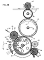
- FIG. 3B A preferred embodiment of the apparatus of the invention is shown in Fig. 3B which is identical to the apparatus shown in Fig. 3A except that second intermediate transfer member 47 has a smaller diameter and in consequence has less surface area.
- second intermediate transfer member 47 cannot hold at any one moment in time the complete latent image which is being transferred from first intermediate transfer member 41.
- all the mulitcolor images are first collected on the first intermediate transfer member and only thereafter is the composite image transferred to the second intermediate transfer member.
- the latent image is transferred from the second intermediate transfer member to final substrate 42 virtually simultaneously as it is being transferred to second intermediate transfer member 47 from first intermediate transfer member 41.
- the inventors have discovered that this configuration results in an enhancement of the quality of the image produced on the final substrate when compared with a configuration in which the second intermediate transfer member is full-sized. In the latter case, the final substrate tends to adhere to the surface of the second intermediate transfer member as the image is being transferred, thereby causing a certain blurring of the image on the final substrate.
- the second intermediate transfer member has a relatively small diameter, preferably less than 40 mm and more preferably less than 30 mm, the separation of the final substrate from the transfer member is improved, there is less tendency to adhesion, and the quality of the image on the final substrate is thereby enhanced.
- the first intermediate transfer member has a diameter of 70 mm or more, as required to hold an A4 sized image, or a 100 mm diameter or more, as required to hold an A3 sized image
- optimal results will be obtained when intermediate transfer member 47 has a diameter of less than about 40 mm or less, preferably about 30 mm or less.
- a duplex embodiment of the invention, for printing two sides of a substrate at the same time is shown in Fig. 4.
- the separate color images which make up the multicolored image to be printed on a first side of substrate 42 are first transferred sequentially to intermediate transfer member 40 and then are transferred, preferably as a group, to second intermediate transfer member 47.
- Second image transfer member 47 is preferably heated to a higher temperature than intermediate transfer member 40.
- the images to be printed on the other side of the page are subsequently transferred sequentially to intermediate transfer member 40, which is meanwhile kept out of transfer engagement with second intermediate transfer member 47.
- Final substrate 42 is then passed between intermediate transfer member 40 and second intermediate transfer member 47, while pressing the two intermediate transfer members together to effect transfer of the images to both sides of the paper by heat and pressure.
- second intermediate transfer member 47 heats substrate 42 and the image to a suitable temperature to assure good transfer of the image on intermediate transfer member 40 to substrate 42.
- the paper may be heated before transfer as described above in connection with Fig. 2.
- intermediate transfer member 40 acts to heat the image to a first temperature during first transfer from photoreceptor 16 to intermediate transfer member 40, and to heat the image to a second higher temperature before second and final transfer from intermediate transfer member 40 to final substrate 42.
- Exemplary embodiments include the apparatus shown in Fig. 5.
- This apparatus is generally the same as the apparatus of Fig. 1, except that a cooling station 60 is operatively associated with intermediate transfer member 40 just before it returns to make contact with photoreceptor surface 16.
- Intermediate transfer member 40 is cooled at cooling station 60 to locally reduce the temperature of intermediate transfer member 40 before and during contact with the image on the photoreceptor. This local cooling allows the liquid toner image to be hotter at the point of final transfer from intermediate transfer member 40 to final substrate 42 than it is at first transfer from photoreceptor surface 16 to intermediate transfer member 40.
- Cooling station 60 may comprise, for example, apparatus for providing a stream of cool air to the surface of the photoreceptor or a cooled roller in contact with the photoreceptor surface. Either or both cooling systems cool intermediate transfer member 40 to a temperature, higher than room temperature, but lower than the final transfer temperature.
- a roller cooler In a multicolor system, if a roller cooler is used it is coated with a non-stick coating to avoid transfer of the image from intermediate transfer member 40 to the roller of cooling station 60.
- FIG. 6 Another exemplary embodiment of this type is illustrated in Fig. 6, which is essentially the same as Fig. 8 of WO 90/04216 previously referenced.
- an intermediate transfer member 140 is of low heat capacity, and is heated only after first transfer is completed.
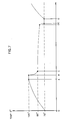
- Fig. 7 which is the same as Fig. 9 of the above referenced application, the temperature at the first transfer is above room temperature in order to improve first transfer, and the temperature at second transfer is even higher to assure complete or nearly complete second transfer.
- the temperatures and heat capacities are selected so that the first transfer takes place at a temperature low enough to avoid back transfer.
- intermediate transfer members 40 and 47 have been described as having heaters placed internal to the core to heat each of them to its required temperature. Other methods of heating intermediate transfer members known in the art can also be used in the practice of the invention.
- Colored liquid developer is prepared in the following manner:
- a mixture of 2.5 parts by weight of Mogul L carbon black (Cabot) and 5 parts by weight of Isopar L are then added to the mix in the double planetary mixer and the resultant mixture is further mixed for one hour at high speed.
- 20 parts by weight of Isopar L preheated to 110°C are added to the mixer and mixing is continued at high speed for one hour.
- the heating unit is then disconnected and mixing is continued until the temperature of the mixture drops to 40°C.
- the resulting mixture is transferred to an S-1 attritor device equipped with 3/16 inch carbon steel media, diluted with Isopar L to a 16% solids ratio and ground without cooling until the temperature rises to about 60° C. Cooling, which reduces the temperature to about 30°C is then commenced and grinding is continued for a total of 24 hours.
- the mixture is removed from the device and diluted with Isopar L to 1.5% by weight solids concentration.
- the particles in the resultant toner concentrate have an average diameter of 2.5 microns.
- Charge director as known in the art, is added to give the final liquid developer.
- the charge director of Example 1 of PCT publication WO 90/14617 is added to give the final liquid developer.
- Pre-heated Isopar L is then added to reduce the solids concentration to preferably 35% and mixing is continued at high speed for one hour. The heating unit is then disconnected and mixing is continued until the temperature of the mixture drops to 40°C.
- the mixture is then transferred to an S-1 attritor device equipped with 3/16 inch carbon steel media and pigment is added to the material in the attritor.
- the mixture is diluted with Isopar L to about a 12-16% solids ratio, depending on the viscosity of the material and is ground without cooling until the temperature rises to about 60°C. Cooling, which reduces the temperature to about 30°C, is then commenced and grinding is continued for a total of 24 hours.
- the mixture is removed from the device and diluted with Isopar L to 1.5% by weight solids concentration.
- the particles in the resultant toner concentrate had an average diameter of 2.5 microns.
- Charge director as known in the art, is added to give the final liquid developer.
- the charge director of Example 1 the above referenced PCT publication WO 90/14617 is added to give the final liquid developer.
- Appropriate colored pigments known in the art of liquid developer manufacture for example the list given in U. S. Patent 4,794,651 can be used.
- Other suitable pigments are Sico Fast Yellow D1350 (BASF), Lithol Rubin D4576 (BASF), Lyonol Blue FG7351 (TOYO) and Lyonol Yellow 7G1310 (TOYO). in amounts and combinations depending on the color and intensity required.
- Aluminum Stearate can be added in small amounts.
- other grinding media such as zirconia may be used.
- These developers are used to form the individual color liquid toner images on photoreceptor surface 16 which comprise a relatively high concentration of toner particles in carrier liquid.
- Photoreceptor surface 16 is preferably formed of selenium.
- Intermediate transfer member 40 is preferably formed of a cylindrical aluminum core coated with a 1 mm thick layer of very soft polyurethane having a hardness of 20-25 Shore A. This layer is covered by an offset printing blanket, preferably a KYNIO AIRTACK offset blanket, which is much harder than the polyurethane.
- a thin conducting layer of conducting acrylic covers this layer and is covered in turn by a 0.1 mm layer of polyurethane of shore A Hardness 20. This layer is overcoated by a thin layer of Syl-Off type 291 or 294 silicone release coating.
- Liquid developer prepared in accordance with the method described above is used in the equipment of Fig. 1.
- the temperature of the intermediate transfer layer should be less than about 50° C.
- Heating intermediate transfer member 40 improves image transfer to intermediate transfer member 40.
- Intermediate transfer member 40 is preferably heated to a temperature somewhat below that at which back transfer begins to occur.
- the improvement in first transfer when the intermediate transfer member is heated may be a consequence of partial solvation of carrier liquid by the pigmented toner particles in the image.
- the pigmented toner particles contained therein solvate the carrier liquid at elevated temperatures. It is believed that there is a partial solvation of the carrier liquid in the toner particles during first transfer to heated intermediate transfer member 40 which may cause the particles to partially coalesce and form a film during first transfer. Coalesced toner is believed to transfer better than uncoalesced toner particles.
- the toner material solvates some of the carrier liquid, the toner particles separate from the unsolvated carrier liquid. It is believed that this separated carrier liquid forms a film between the toner image and the photoreceptor which reduces the adhesion of the image to the photoreceptor, aiding complete transfer of the image to the intermediate transfer member.
- the heating of the image before and/or during final transfer insures the complete or nearly complete transfer of the image from the intermediate transfer member to the final substrate.
- this image heating comes solely by conduction from the paper, it has been found experimentally that the paper should be at a temperature of at least about 70° C. Higher temperatures such as 80 or 90°can also be used, but substantially lower temperatures do not tackify the image enough to assure complete transfer from intermediate transfer member 40 to paper 42.
- the precise temperatures used for particular configurations and combinations are a function of the material properties of the toner particles and the carrier liquid as well as of the quality of the release layer on the intermediate transfer member.
- Back transfer occurs due to the tackiness of the image, but is also influenced by the relative adhesion of the image to the release layer on the intermediate transfer member and to the photoreceptor. It would be possible to increase the temperature of the intermediate transfer member if the release properties of the surface of the intermediate transfer member were poorer. This however would also result in poorer transfer to the final substrate.
- the following temperatures are used.
- the intermediate transfer member is heated to a surface temperature of 100°C and the paper is not heated. Calculations show that the image is at a temperature of 52°C to 63°C during first transfer. During the interval between first and second transfer the image temperature rises to the intermediate transfer member's temperature of 100° C, and the image is cooled during second, final transfer to paper to a temperature of 73°C to 78°C.
- the intermediate transfer member is heated to 50° C and backing roller 43 is heated to 120° C.
- the image temperature on first transfer is approximately 43° C and on second transfer it is 75°C to 78°C.
- the temperatures shown in figure 7 are also representative of values suitable for single image transfer.
- the first transfer temperature must be low enough to assure that no back transfer takes place.
Landscapes
- Physics & Mathematics (AREA)
- General Physics & Mathematics (AREA)
- Electrostatic Charge, Transfer And Separation In Electrography (AREA)
Claims (14)
- Bilderzeugungsvorrichtung zum Drucken eines Bildes auf ein Substrat von einem latenten Bild, das auf einer ein latentes Bild tragenden Oberfläche gebildet ist, miteiner Entwicklungseinrichtung (22) zum Entwickeln des latenten Bildes mit Toner zur Bildung eines entwickelten Toner-Bildes einer gegebenen Größe;einem ersten zylindrischen Zwischenübertragungselement (40) mit einem ersten Durchmesser;einer ersten Übertragungseinrichtung zum Übertragen des entwickelten Toner-Bildes von der ein latentes Bild tragenden Oberfläche zu dem ersten zylindrischen Zwischenübertragungselement;einem zweiten zylindrischen Zwischenübertragungselement (47) undeiner zweiten Übertragungseinrichtung zum Übertragen des entwickelten Bildes von dem ersten Zwischenübertragungselement auf das zweite Zwischenübertragungselement und von dem zweiten Zwischenübertragungselement auf das Substrat,dadurch gekennzeichnet, daß das zweite zylindrische Zwischenübertragungselement einen kleineren Durchmesser als den Durchmesser des ersten-zylindrischen Zwischenübertragungselementes hat.
- Bilderzeugungsvorrichtung nach Anspruch 1, wobei das erste zylindrische Zwischenübertragungselement eine Oberfläche hat, die groß genug zur Aufnahme des entwickelten Toner-Bildes ist.
- Bilderzeugungsvorrichtung nach Anspruch 1 oder 2, wobei das zweite Zwischenübertragungselement nicht groß genug zur Aufnahme des entwickelten Bildes ist.
- Bilderzeugungevorrichtung nach einem der vorhergehenden Ansprüche, mit einer Zwischenübertragungselement-Heizeinrichtung (46, 48) zum Erwärmen des ersten Zwiechenübertragungselementes auf eine erste Temperatur und zum Erwärmon des zweiten zwischenübertragungselementes auf eine zweite. Temperatur, die höher ist als die erste Temperatur.
- Bilderzeugungsvorrichtung nach einem der vorhergehenden Ansprüche, wobei die zweite Übertragungseinrichtung eine zweite Heizeinrichtung (43) zum Erwärmen des substrates aufweist.
- Bilderzeugungsvorrichtung nach Anspruch 5, wobei die zweite Heizeinrichtung eine Heiz-Andruckwalze (43) aufwelst, die das Aufbringen von Wärme und Druck auf das Bild während der Bildübertragung bewirkt.
- Bilderzeugungsvorrichtung nach einem der vorhergehenden Ansprüche, mit einer ersten Spannungseinrichtung, um das erste zwigchenübertragungselement auf einer ersten elektrischen Spannung zu halten.
- Bilderzeugungsvorrichtung nach Anspruch 7, wobei wenigstens ein Bereich der das latente Bild tragenden Oberfläche bei einer zweiten elektrischen Spannung liegt und die erste Spannung von der zweiten Spannung abweicht.
- Bilderzeugungsvorrichtung nach Anspruch 7 oder 8, mit einer zweiten spannungseinrichtung, um das zweite Zwischenübertragungselement auf einer dritten elektrischen Spannung zu halten.
- Bilderzeugungsvorrichtung nach einem der vorhergehenden Ansprüche, wobei der Toner ein Flüssigtoner mit Trägerflüssigkeit und Tonerteilchen ist.
- Bilderzeugungsvorrichtung nach einem der vorhergehenden Ansprüche, wobei das zweite zylindrische Zwischenübertragungs element einen Durchmesser von weniger als etwa 40 mm hat.
- Bilderzaugungsvorrichtung nach einem der vorausgehenden Ansprüche, wobei das zweite Zwischenübertragungselement einen Durchmesser von weniger als 30 mm hat.
- Bilderzeugungsvorrichtung nach einem der vorhergehenden Ansprüche, wobei die Übertragung des entwickelten Bildes von dem zweiten zylindrischen zwischenübertragungselement auf das Substrat beginnt, bevor die Übertragung des entwickelten Bildes von dem ersten zwischenübertragungselement auf das zweite Übertragungselement vollendet ist.
- Bilderzeugungsvorrichtung nach einem der vorhergehenden Ansprüche, mit Einrichtungen zur Erzeugung einer Mehrzahl entwickelter Bilder auf der bildtragenden oberfläche und zum übertragen der Mehrzahl entwickelter Bilder auf das erste zylindrische Übertragungselement in gegenseitiger Fluchtung.
Applications Claiming Priority (1)
| Application Number | Priority Date | Filing Date | Title |
|---|---|---|---|
| PCT/NL1991/000050 WO1992017825A1 (en) | 1989-01-04 | 1991-03-26 | Imaging system with intermediate transfer members |
Publications (2)
| Publication Number | Publication Date |
|---|---|
| EP0577597A1 EP0577597A1 (de) | 1994-01-12 |
| EP0577597B1 true EP0577597B1 (de) | 1996-05-15 |
Family
ID=19858720
Family Applications (1)
| Application Number | Title | Priority Date | Filing Date |
|---|---|---|---|
| EP91907895A Expired - Lifetime EP0577597B1 (de) | 1991-03-26 | 1991-03-26 | Bilderzeugungsystem mit einem zwischenubertragungselement |
Country Status (5)
| Country | Link |
|---|---|
| US (1) | US5410392A (de) |
| EP (1) | EP0577597B1 (de) |
| JP (1) | JPH06508444A (de) |
| DE (1) | DE69119612T2 (de) |
| HK (1) | HK199296A (de) |
Cited By (1)
| Publication number | Priority date | Publication date | Assignee | Title |
|---|---|---|---|---|
| EP1378801A1 (de) * | 2001-04-03 | 2004-01-07 | Pfu Limited | Transfer-/fixiersystem eines elektrofotografischen flüssigkeits-entwicklungssystems |
Families Citing this family (38)
| Publication number | Priority date | Publication date | Assignee | Title |
|---|---|---|---|---|
| US5438398A (en) * | 1992-05-29 | 1995-08-01 | Canon Kabushiki Kaisha | Image forming apparatus with intermediate transfer member |
| WO1995015854A1 (de) * | 1993-12-11 | 1995-06-15 | Eltex-Elektrostatik Gmbh | Vorrichtung sowie verfahren zum herstellen von bedruckten blättern |
| US5561510A (en) * | 1995-01-31 | 1996-10-01 | Eastman Kodak Company | Image forming method utilizing intermediate transfer |
| US5537194A (en) * | 1995-10-11 | 1996-07-16 | Xerox Corporation | Liquid developer compatible intermediate toner transfer member |
| US5728502A (en) * | 1996-03-12 | 1998-03-17 | Minnesota Mining And Manufacturing Company | Imaging medium, method of imaging said medium, and image-bearing medium |
| US5737678A (en) * | 1996-07-01 | 1998-04-07 | Xerox Corporation | Liquid immersion development machine having a multiple intermediate members image transfer assembly |
| KR100200620B1 (ko) * | 1996-09-13 | 1999-06-15 | 윤종용 | 양면인쇄가 가능한 전자사진방식 프린터 |
| US6015603A (en) * | 1997-04-30 | 2000-01-18 | 3M Innovative Properties Company | Imaging medium comprising polyvinyl chloride, method of imaging said medium, and image-bearing medium |
| US5858516A (en) * | 1997-04-30 | 1999-01-12 | Minnesota Mining & Manufacturing Company | Imaging medium comprising polycarbonate, method of making, method of imaging, and image-bearing medium |
| US5832352A (en) * | 1997-06-13 | 1998-11-03 | Xerox Corporation | Method and apparatus for increasing the mechanical strength of intermediate images for liquid development image conditioning |
| US6205920B1 (en) | 1998-09-24 | 2001-03-27 | Day International, Inc. | Continuous image transfer belt and variable image size offset printing system |
| US6061544A (en) * | 1998-11-20 | 2000-05-09 | Eastman Kodak Company | Maximizing image gloss uniformity by minimizing the effect of temperature droop in a fuser for reproduction apparatus |
| US6088565A (en) * | 1998-12-23 | 2000-07-11 | Xerox Corporation | Buffered transfuse system |
| US6498918B1 (en) * | 1999-06-28 | 2002-12-24 | Xerox Corporation | Polythiophene filled xerographic component coatings |
| EP1192507B1 (de) | 1999-07-05 | 2004-09-29 | Hewlett-Packard Indigo B.V. | Verfahren zum Übertragen eines Tonerbildes |
| GB9923496D0 (en) | 1999-10-06 | 1999-12-08 | Xeikon Nv | Single-pass multi-colour printer and method of printing |
| AU1379201A (en) * | 1999-11-24 | 2001-06-04 | Jing Li | A composite material having triangular cavity structure |
| JP2003533741A (ja) | 2000-05-17 | 2003-11-11 | ヒューレット−パッカード・インデイゴ・ビー・ブイ | 蛍光液体トナー並びにこれを用いたプリント方法 |
| JP4143256B2 (ja) * | 2000-11-30 | 2008-09-03 | 株式会社リコー | 画像形成装置 |
| IL144326A0 (en) * | 2001-07-15 | 2002-05-23 | Indigo Nv | Liquid toner with additives for enhancing life of intermediate transfer members |
| JP3954431B2 (ja) * | 2002-04-26 | 2007-08-08 | 株式会社リコー | 画像形成装置 |
| JP2004145260A (ja) * | 2002-07-04 | 2004-05-20 | Ricoh Co Ltd | 定着装置・画像形成装置・記録媒体の再生方法 |
| US7005225B2 (en) * | 2002-11-12 | 2006-02-28 | Samsung Electronics Company | Organosol including amphipathic copolymeric binder having crystalline material, and use of the organosol to make dry tones for electrographic applications |
| US7074537B2 (en) * | 2002-11-12 | 2006-07-11 | Samsung Electronics Company | Organosol liquid toner including amphipathic copolymeric binder having crystalline component |
| US7135264B2 (en) * | 2002-11-12 | 2006-11-14 | Samsung Electronics Company | Organosol including amphipathic copolymeric binder and use of the organosol to make dry toners for electrographic applications |
| US7166405B2 (en) * | 2002-11-12 | 2007-01-23 | Samsung Electronics Company | Organosol including high Tg amphipathic copolymeric binder and liquid toners for electrophotographic applications |
| US7014973B2 (en) * | 2002-11-12 | 2006-03-21 | Samsung Electronics Company | Organosol including amphipathic copolymeric binder made with Soluble High Tg Monomer and liquid toners for electrophotographic applications |
| US7052816B2 (en) * | 2003-01-03 | 2006-05-30 | Samsung Electronics Company | Organosol liquid toner including amphipathic copolymeric binder having crosslinkable functionality |
| US6796197B1 (en) | 2003-05-30 | 2004-09-28 | Samsung Electronics Co., Ltd. | Device and method for screening liquid toners and receptors for use with liquid toners in electrophotography |
| US20040240897A1 (en) * | 2003-05-30 | 2004-12-02 | Samsung Electronics Co. Ltd | Liquid toner screening device |
| US7060408B2 (en) * | 2003-12-30 | 2006-06-13 | Samsung Electronics Company | Liquid toner comprising encapsulated pigment, methods and uses |
| US7105263B2 (en) | 2003-12-30 | 2006-09-12 | Samsung Electronics Company | Dry toner comprising encapsulated pigment, methods and uses |
| US7189484B2 (en) * | 2003-12-31 | 2007-03-13 | Samsung Electronics Co., Ltd. | Reduced light scattering in projected images formed from electrographic toners |
| US7151603B2 (en) * | 2004-04-30 | 2006-12-19 | Samsung Electronics Co. Ltd. | Overhead transparency clarity simulator |
| JP4153530B2 (ja) * | 2006-04-26 | 2008-09-24 | シャープ株式会社 | 画像形成装置 |
| JP5326286B2 (ja) * | 2008-01-25 | 2013-10-30 | 株式会社リコー | 画像形成装置 |
| DE102015211537A1 (de) | 2014-07-24 | 2016-01-28 | Heidelberger Druckmaschinen Ag Intellectual Property | Verfahren zum Transfer eines Druckbildes auf ein Substrat |
| JP7342514B2 (ja) | 2019-08-14 | 2023-09-12 | 富士フイルムビジネスイノベーション株式会社 | ジャケット、転写装置、および画像形成装置 |
Family Cites Families (16)
| Publication number | Priority date | Publication date | Assignee | Title |
|---|---|---|---|---|
| DE1929671B2 (de) * | 1968-06-12 | 1976-09-09 | Canon KJC., Tokio | Elektrofotografisches verfahren zur herstellung einer mehrfarbigen kopie von einer mehrfarbigen vorlage auf einem nicht masshaltigen bildempfangsmaterial |
| US3847478A (en) * | 1973-12-17 | 1974-11-12 | Xerox Corp | Segmented bias roll |
| US3863603A (en) * | 1974-01-07 | 1975-02-04 | Ibm | Magnetic brush roll having resilient polymeric surface |
| US3959574A (en) * | 1974-04-26 | 1976-05-25 | Xerox Corporation | Biasable member and method for making |
| GB1544050A (en) * | 1976-06-16 | 1979-04-11 | Fuji Photo Film Co Ltd | Marking apparatus |
| DE3214677C2 (de) * | 1982-04-21 | 1985-08-08 | Canon K.K., Tokio/Tokyo | Mehrfarbenkopiergerät |
| US4518976A (en) * | 1982-11-17 | 1985-05-21 | Konishiroku Photo Industry Co., Ltd. | Recording apparatus |
| JPS59166980A (ja) * | 1982-11-29 | 1984-09-20 | Konishiroku Photo Ind Co Ltd | 静電画像記録装置 |
| US4794651A (en) * | 1984-12-10 | 1988-12-27 | Savin Corporation | Toner for use in compositions for developing latent electrostatic images, method of making the same, and liquid composition using the improved toner |
| US4690539A (en) * | 1986-05-27 | 1987-09-01 | Xerox Corporation | Transfer apparatus |
| US4684238A (en) * | 1986-06-09 | 1987-08-04 | Xerox Corporation | Intermediate transfer apparatus |
| US4708460A (en) * | 1986-07-25 | 1987-11-24 | Xerox Corporation | Simultaneous transfer and fusing in electrophotography |
| GB8823256D0 (en) * | 1988-10-04 | 1988-11-09 | Spectrum Sciences Bv | Imaging apparatus |
| US4974027A (en) * | 1989-02-06 | 1990-11-27 | Spectrum Sciences B.V. | Imaging system with compactor and squeegee |
| US5047306A (en) * | 1989-05-19 | 1991-09-10 | Spectrum Sciences B. V. | Humidity tolerant charge director compositions |
| US5150161A (en) * | 1991-04-09 | 1992-09-22 | Olin Corporation | Color printing apparatus and process using first and second transfer surfaces |
-
1991
- 1991-03-26 DE DE69119612T patent/DE69119612T2/de not_active Expired - Lifetime
- 1991-03-26 JP JP3507718A patent/JPH06508444A/ja active Pending
- 1991-03-26 EP EP91907895A patent/EP0577597B1/de not_active Expired - Lifetime
- 1991-03-26 US US08/119,203 patent/US5410392A/en not_active Expired - Lifetime
-
1996
- 1996-10-31 HK HK199296A patent/HK199296A/xx not_active IP Right Cessation
Cited By (2)
| Publication number | Priority date | Publication date | Assignee | Title |
|---|---|---|---|---|
| EP1378801A1 (de) * | 2001-04-03 | 2004-01-07 | Pfu Limited | Transfer-/fixiersystem eines elektrofotografischen flüssigkeits-entwicklungssystems |
| EP1378801A4 (de) * | 2001-04-03 | 2009-07-15 | Pfu Ltd | Transfer-/fixiersystem eines elektrofotografischen flüssigkeits-entwicklungssystems |
Also Published As
| Publication number | Publication date |
|---|---|
| DE69119612T2 (de) | 1996-12-12 |
| EP0577597A1 (de) | 1994-01-12 |
| JPH06508444A (ja) | 1994-09-22 |
| HK199296A (en) | 1996-11-08 |
| US5410392A (en) | 1995-04-25 |
| DE69119612D1 (de) | 1996-06-20 |
Similar Documents
| Publication | Publication Date | Title |
|---|---|---|
| EP0577597B1 (de) | Bilderzeugungsystem mit einem zwischenubertragungselement | |
| US5276492A (en) | Imaging method and apparatus | |
| US5926679A (en) | Method and apparatus for forming an image for transfer to a receiver sheet using a clear toner and sintering of a pigmented toner layer | |
| EP0609966B1 (de) | Bilderzeugungssystem mit Zwischenübertragungselement | |
| EP0725322B1 (de) | Trockenentwicklungsverfahren mit Flüssigtoner | |
| US5017967A (en) | Method and apparatus for forming images including a toner transporting member having an insulating layer | |
| US5347353A (en) | Tandem high productivity color architecture using a photoconductive intermediate belt | |
| US6496676B1 (en) | Liquid developer system employing a pretransfer station | |
| US5572274A (en) | Liquid developer imaging system and method utilizing an intermediate transfer member | |
| JPH09179417A (ja) | 転写定着部材 | |
| US5519476A (en) | Liquid electrophotographic reproduction machine having a desired abrasion fix level | |
| US5815783A (en) | Method and apparatus for printing on both sides of a substrate | |
| WO1992017825A1 (en) | Imaging system with intermediate transfer members | |
| JP2002202682A (ja) | 定着器等の粘着性クリーナをリフレッシュする方法 | |
| EP0486534B1 (de) | Verfahren und gerät zur bildherstellung | |
| US8023846B2 (en) | Segmented roller for flood coating system | |
| EP0753797B1 (de) | Bilderzeugungsmethode mit Zwischenübertragungselement | |
| US20060039715A1 (en) | Electrostatographic apparatus with cleaning device for controlling release oil transfer | |
| EP1103861B1 (de) | Mehrfarben Bildwiedergabemaschine mit Druckmethode für Ladungsumkehr | |
| DE69030271T2 (de) | Bilderzeugungssystem mit Zwischenübertragungselement | |
| DE69033709T2 (de) | Bilderzeugungsmethode mit Zwischenübertragungselement | |
| US5576817A (en) | Dual zone development for liquid developers | |
| JP5030636B2 (ja) | 湿式画像形成装置 | |
| JPH07210019A (ja) | 定着方法 | |
| JPH03164762A (ja) | 湿式現像のカラー画像形成方法 |
Legal Events
| Date | Code | Title | Description |
|---|---|---|---|
| PUAI | Public reference made under article 153(3) epc to a published international application that has entered the european phase |
Free format text: ORIGINAL CODE: 0009012 |
|
| 17P | Request for examination filed |
Effective date: 19930922 |
|
| AK | Designated contracting states |
Kind code of ref document: A1 Designated state(s): DE FR GB IT |
|
| RAP1 | Party data changed (applicant data changed or rights of an application transferred) |
Owner name: INDIGO N.V. |
|
| 17Q | First examination report despatched |
Effective date: 19940412 |
|
| GRAH | Despatch of communication of intention to grant a patent |
Free format text: ORIGINAL CODE: EPIDOS IGRA |
|
| GRAA | (expected) grant |
Free format text: ORIGINAL CODE: 0009210 |
|
| AK | Designated contracting states |
Kind code of ref document: B1 Designated state(s): DE FR GB IT |
|
| ITF | It: translation for a ep patent filed | ||
| ET | Fr: translation filed | ||
| REF | Corresponds to: |
Ref document number: 69119612 Country of ref document: DE Date of ref document: 19960620 |
|
| PLBE | No opposition filed within time limit |
Free format text: ORIGINAL CODE: 0009261 |
|
| STAA | Information on the status of an ep patent application or granted ep patent |
Free format text: STATUS: NO OPPOSITION FILED WITHIN TIME LIMIT |
|
| 26N | No opposition filed | ||
| REG | Reference to a national code |
Ref country code: GB Ref legal event code: IF02 |
|
| PGFP | Annual fee paid to national office [announced via postgrant information from national office to epo] |
Ref country code: IT Payment date: 20070523 Year of fee payment: 17 |
|
| PG25 | Lapsed in a contracting state [announced via postgrant information from national office to epo] |
Ref country code: IT Free format text: LAPSE BECAUSE OF NON-PAYMENT OF DUE FEES Effective date: 20080326 |
|
| PGFP | Annual fee paid to national office [announced via postgrant information from national office to epo] |
Ref country code: FR Payment date: 20100406 Year of fee payment: 20 |
|
| PGFP | Annual fee paid to national office [announced via postgrant information from national office to epo] |
Ref country code: GB Payment date: 20100326 Year of fee payment: 20 |
|
| PGFP | Annual fee paid to national office [announced via postgrant information from national office to epo] |
Ref country code: DE Payment date: 20100329 Year of fee payment: 20 |
|
| REG | Reference to a national code |
Ref country code: DE Ref legal event code: R071 Ref document number: 69119612 Country of ref document: DE |
|
| REG | Reference to a national code |
Ref country code: GB Ref legal event code: PE20 Expiry date: 20110325 |
|
| PG25 | Lapsed in a contracting state [announced via postgrant information from national office to epo] |
Ref country code: GB Free format text: LAPSE BECAUSE OF EXPIRATION OF PROTECTION Effective date: 20110325 |
|
| PG25 | Lapsed in a contracting state [announced via postgrant information from national office to epo] |
Ref country code: DE Free format text: LAPSE BECAUSE OF EXPIRATION OF PROTECTION Effective date: 20110326 |