EP0577408A2 - Kohlenstoff-Faser mit hoher Druckfestigkeit aus Pech - Google Patents
Kohlenstoff-Faser mit hoher Druckfestigkeit aus Pech Download PDFInfo
- Publication number
- EP0577408A2 EP0577408A2 EP19930305113 EP93305113A EP0577408A2 EP 0577408 A2 EP0577408 A2 EP 0577408A2 EP 19930305113 EP19930305113 EP 19930305113 EP 93305113 A EP93305113 A EP 93305113A EP 0577408 A2 EP0577408 A2 EP 0577408A2
- Authority
- EP
- European Patent Office
- Prior art keywords
- pitch
- compressive strength
- crystal
- carbon fiber
- based carbon
- Prior art date
- Legal status (The legal status is an assumption and is not a legal conclusion. Google has not performed a legal analysis and makes no representation as to the accuracy of the status listed.)
- Withdrawn
Links
Images
Classifications
-
- D—TEXTILES; PAPER
- D01—NATURAL OR MAN-MADE THREADS OR FIBRES; SPINNING
- D01F—CHEMICAL FEATURES IN THE MANUFACTURE OF ARTIFICIAL FILAMENTS, THREADS, FIBRES, BRISTLES OR RIBBONS; APPARATUS SPECIALLY ADAPTED FOR THE MANUFACTURE OF CARBON FILAMENTS
- D01F9/00—Artificial filaments or the like of other substances; Manufacture thereof; Apparatus specially adapted for the manufacture of carbon filaments
- D01F9/08—Artificial filaments or the like of other substances; Manufacture thereof; Apparatus specially adapted for the manufacture of carbon filaments of inorganic material
- D01F9/12—Carbon filaments; Apparatus specially adapted for the manufacture thereof
- D01F9/14—Carbon filaments; Apparatus specially adapted for the manufacture thereof by decomposition of organic filaments
- D01F9/145—Carbon filaments; Apparatus specially adapted for the manufacture thereof by decomposition of organic filaments from pitch or distillation residues
Definitions
- This invention relates to a pitch based carbon fiber.
- PAN and Rayon based carbon fibers made of polyacrylonitrile and rayon, respectively are finding extensive applications as carbon fibers having high tensile strength and high tensile modulus elasticity, for instance.
- the precursors of these fibers are expensive and are inferior in the carbonization yield. Therefore, it suffers economical problems. Also, it is very difficult to produce high elastic modulus products with a tensile elastic modulus of 60 ton/mm2 or above from the PAN or Rayon based carbon fibers noted above.
- Japanese Patent Laid-Open No. 54-55625 shows a method of obtaining a liquid crystal pitch with an optically anisotropic phase content of substantially 100 % through the long thermal pyrolysis, polymerization and/or condensation reactions by combining bubbling with inert gas and stirring
- Japanese Patent Laid-Open No. 54-160427 shows a method of obtaining a liquid crystal pitch with an optically anisotropic phase content of substantially 100 % in a solvent extraction process.
- Japanese Patent Publication No. 61-38755 shows a method of obtaining a liquid crystal pitch with substantially 100 % optically anisotropic phase content by heat treating the precursor pitch to produce an optically anisotropic phase-containing pitch and then subjecting the optically anisotropic phase-containing pitch to specific gravity difference separation.
- the obtainable liquid crystal pitch with substantially 100 % optically anisotropic phase content has a softening point of 230 to 320 °C , which is very low compared to those liqiud crystal pitches for pitch based carbon fibers disclosed in the above-mentioned Jpanese Patent Laid-Open Nos. 54-55625 and 54-160427, and thus it can be stably spun at a temperature of from 280 to 380 °C .
- the liquid crystal pitch obtained in this way is melt spun at a temperature of 280 to 380 °C to obtain pitch fibers, which are then oxidatively stabilized at 200 to 350 °C and then carbonaized and graphitized at a high temperature of around 500 to 3,000°C in an inert gas atmosphere to obtain carbon fibers. If necessary, an elongation treatment is carried out simultaneously with the stabilization and carbonization processes.
- the pitch based carbon fibers which are obtained in the above way, have been improved in the orientation of the constituent molecules of the liquid crystal pitch.
- a high degree of the axial orientation of the molecules isattainable.
- Such pitch based carbon fibers show not only higher tensile strength and modulus but higher thermal and electric conductivities.
- the pitch based carbon fibers provide higher tensile strength and especially tensile modulus caused by their higher graphitizabity, they have a significant problem that their compressive strength is extremely reduced with improvement of the crystallization degree.
- the compressive strength is as low as 66 to 83 kg/mm2 with a tensile elastic modulus of 50 ton/mm2 and 58 to 66 kg/mm2 with a tensile elastic modulus of 70 ton/mm2.
- the inventors conducted extensive researches and experiments with an aim of obtaining carbon fibers, which can meet such demands, particularly those having high tensile elastic modulus and high compressive strength. As a result, it was found that crystal fibriles constituting carbon fibers have non-uniform crystal structure distribution over a crystal thickness range of 15 to 300 %, sometimes 10 to 400 %, of the average thickness Lav., thus leading to non-uniform stress concentration at compression. The compressive strength, therefore, was low.
- the crystal fibriles constituting carbon fibers have thicknesses held within a narrow range with respect to the average thickness Lav. and thus have high uniformity of crystal structure, it is possible to obtain uniform compressive strength distribution over each crystal fibril to obtain high compressive strength.
- the present invention is predicted on the above findings.
- uniformity of the molecular weight distribution of the liquid crystal pitch and also uniformity of the orientation of the pitch constituent molecules along the fiber axis with multiple stage high shear spinning uniform crystal structure of carbon fibers can be attained to realize carbon fibers having high compressive strength and nevertheless having high tensile elastic modulus.
- the invention provides a pitch based carbon fiber of high elastic modulus and high compressive strength, as well as a method of mating such fiber, which has improved compressive strength over the prior art pitch based carbon fiber while maintaining high tensile elastic modulus.
- high compressive strength pitch based carbon fiber has a uniform crystal structure distribution with substantially all the crystal fibriles constituting the carbon fiber having thicknesses ranging from 3o to 200 % of the average thickness Lav.
- the thickness of substantially all the crystal fibriles constituting the carbon fiber ranges from 50 to 180 % of their average thickness Lav.
- the individual crystal fibriles constituting the carbon fiber have thickness fluctuation range within ⁇ 20%, preferably ⁇ 15%, of the average and also have uniformity in the axial direction.
- the above high compressive strength pitch based carbon fiber has a compressive strength ranging from 100 kg/mm2 to 170kg/mm2 with a tensile elastic modulus of 50 ton/mm2 and ranging from 85 kg/mm2 to 135 kg/mm2 with a tensile elastic modulus of 70 ton/mm2.
- the liquid crystal pitch which has a narrow molecular weight distribution range, practically a range of 300 to 5,000, preferably 320 to 4,000 , and spin the pitch while applying super-high shear of 7 to 50 kg/ cm2, preferably 15 to 30 kg/cm2 (usual shear applied being 0.1 to 1 kg/cm2), in two or more stages for increase and uniformalization of the shear acting on the pitch constituents in the fiber axis direction (i.e., nozzle shear stress).
- the shear acting on the pitch in the sectional directi ons of the nozzle has a distribution, that is, it is highest adjacent the inner wall surface of the nozzle and reduces as one goes toward the nozzle center.
- Non-uniformity of applied shear in the sectional direction of nozzle leads to non-uniformity of the molecular orientation of pitch constituent molecules in the nozzle sectional direction and ultimately leads to non-uniformity of the thickness of the carbon fiber crystal fibriles in the direction of the fiber section.
- high shear may be applied to the pitch as the pitch passes through the nozzle. However, even this method is insufficient for obtaining uniform shear application.
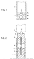
- a liquid crystal pitch of a narrow molecular weight distribution range may be spun by using a nozzle 10 as shown in Fig. 1.
- the nozzle 10 has a plurality of different accommodated nozzles 9 with individual central capillaries 8a, 8b and 8c.
- the high shear noted above is applied in the capillaries 8a, 8b and 8c.
- Enlarged spaces 8 between the capillaries 8a and 8b and between the capillaries 8b and 8c serve as shear alleviation spaces. Unless these spaces are provided, the spinning becomes impossible due to extreme pressure increase.
- the resultant carbon fibers would have radial cracks from the surface to the core of the fiber and have inferior physical properties.
- the diameter of the shear alleviation spaces is extremely large compared to the capillary diameter, the orientation produced by high shear application receives excess alleviation and is spoiled.
- the relation between the capillary diameter Dc and the diameter Dr of the shear alleviation spaces is suitably Dr ⁇ 5Dc. Under this condition, it is possible to prevent the disability of spinning due to extreme pressure increase during the multiple stage high shear application, thus obtaining a uniformity of pitch molecule orientation in the sectional direction of the fiber that can not be obtained in the prior art.
- the stabilization process is suitably carried out by selecting a condition, under which it is possible to obtain more uniform oxygen uptake in the direction of the fiber section in an oxidation atmosphere (for instance, as slow heating rate as 4°C /min. or below in air).
- a condition under which it is possible to obtain more uniform oxygen uptake in the direction of the fiber section in an oxidation atmosphere (for instance, as slow heating rate as 4°C /min. or below in air).
- the more uniform the oxygen distribution in the fibers obtained in the stabilization process the more uniform crystal structure in the fiber section and fiber axis direction is obtainable after carbonization or graphitization, and it is the more readily possible to obtain uniform crystal structure carbon fibers with fiber crystal fibriles thereof having thicknesses ranging from 30 to 200 % of the average thickness Lav.
- the carbon fibers with uniform crystal structure obtainable by the application of the multiple stage high shear spinning are excellent not only in the uniformity of crystal fibril thickness distribution but also in the thickness uniformity of the individual crystal fibriles in the fiber axis direction.
- liquid crystal pitch it is important to use the pitch of a narrow molecular weight distribution range with a practical molecular weight distribution range of 300 to 5,000, preferably 320 to 4,000, while having an optically anisotropic phase content of 95 % or above and an average molecular weight of 1,600 or below. Besides, such liquid crystal pitch is spun with an extremely high viscosity of 800 to 15,000 poise.
- the liquid crystal pitch used may be prepared from petroleum or coal tar derived pitches, or from aromatic hydrocarbons. From such precursors, the liqid crystal pitch with a practical molecular weight distribution range of 300 to 5,000 and an optically anisotropic phase content of 95 % or above. is prepared by any of the various conventional methods noted above. Preferably, the liquid crystal pitch has a further narrow molecular weight distribution range of 320 to 4,000 and an optically anisotropic phase content of 98 % or above, i.e., substantially 100 %.
- liquid crystal pitch used has an optically anisotropic phase content below 95 %, or if it has a molecular weight distribution range above 5,000, it is difficult to obtain the pitch based carbon fibers of high tensile strength and high tensile elastic modulus.
- the viscosity of the liquid crystal pitch at spinning suitably ranges from 800 to 15,000 poise, preferably from 2,000 to 7,000 poise. If the viscosity is below 800 poise, the pitch can not be high shear application spun. In this case, the stacking of the liquid crystal molecules can not be suppressed, and therefore the thickness of the resultant crystal fibriles is increased to reduce the compressive strength of the obtainable carbon fibers. If the viscosity is above 15,000 poise, on the other hand, frequent filamnent breakage occurs during the spinning, thus making the spinning difficult.
- the liquid crystal pitch of the specific molecular weight distribution range and spin the pitch by the application of multiple stage high shear spinning, in which shear (i.e., shear stress in the spinning nozzle) as high as 7 to 50 kg/cm2, preferably 15 to 30 kg/cm2 is applied to the pitch when the pitch passes through the nozzle. If the shear is below 7 kg/cm2, sufficient molecular orientation along the fiber axis can not be obtained. If the shear is above 50 kg/cm2 on the other hand, frequent filament breakage occurs during spinning, thus making the spinning difficult. If the spinning could be done, radial cracks are generated from the surface to the core of the resultant carbon fibers, that is, it is impossible to obtain high performance carbon fibers.
- shear i.e., shear stress in the spinning nozzle
- the pitch fibers obtained in the above way are then stabilized in an oxidation gas atmosphere at 200 to 350 °C and then carbonized in an inert gas atmosphere at 500 to 3,000 °C to obtain carbon fibers. If necessary, the pitch fibers are elongated simultaneously with the stabilization and carbonization processes.
- the high compressive strength pitch based carbon fibers as above according to the invention has uniform crystal structure distribution with substantially all their constituent crystal fibriles having thicknesses ranging from 30 to 200 % of the average thickness Lav. Uniform stress distribution over uniform crystals thus can be obtained to suppress non-linearity of the compressive elastic modulus and thus greatly improve the compressive strength.
- the prior art carbon fibers has non-linearity of the compressive elastic modulus, i.e., increase of the compressive stress and reduction of the compressive elastic modulus, due to stress concentration on crystals stemming from lack of uniformity of the crystal structure. Therefore, the compressive strength is low.
- the compressive strength of the carbon fibers according to the invention is specifically 100 to 170 kg/mm2 with a tensile elastic modulus of 50 ton/mm2 and 85 to 135 kg/mm2 with a tensile elastic modulus of 70 ton/mm2. In comparison, with the prior art product, it is about 75 kg/mm2 with a tensile elastic modulus of 50 ton/mm2 and 65 kg/mm2 with a tensile elastic modulus of 70 ton/mm2. This means that the carbon fibers according to the invention have improved compressive strength by 30 to 120 % over the prior art product.
- optically anisotropic phase used in the specification may not always be used with the same meaning in scientific societies and various technical literatures.
- optically anisotropic phase is meant a pitch component, of which a bright spot can be recognized when a polished section of a pitch mass solidified in the neighborhood of room temperature is observed with a reflection polarization microscope through a Nicol's orthgonal prism by rotating the sample or the prism, that is, which is optically anisotropic.
- a component which is optically isotropic is referred to as optically isotropic phase.
- the optically anisotropic phase Compared to the optically isotropic phase, the optically anisotropic phase has main component molecules having a chemical structure, in which polycyclic and polypcondensed aromatic rings have associated together in the form of a laminate of planes. It is thought to be in a sort of liquid crystal state at the melting temperature. Thus, when it is extruded through a thin spinning nozzle, its molecules are oriented such that their plane is parallel to the fiber axis direction. For this reason, the carbon fibers obtained from this optically anisotropic pitch have high strength and high modulus.
- the optically anisotropic phase is determined by observing and photographing it in the presence of a Nicol's orthogonal prism of polarization microscope and measuring the area occupation factor of the optically anisotropic part. It is thus represented by percent by volume in practice.
- ⁇ the shear (shear stress)
- ⁇ the pitch melt viscosity
- Q the rate of pitch discharge
- g c the gravitational acceleration
- D is the spinning nozzle diameter.
- FIG. 2 schematically shows a strand compressive tester used for the measurement.
- a strand test piece 1 with a diameter of 1 mm which was prepared by using fibers and a resin, was fitted using epoxy resin in stainless steel tubes 2 with a diameter of 1 mm and a length of 30 mm. The assembly was then fitted in stainless steel holders 4 and 5, which were then mounted in a sleeve 6.
- the compressive strength determined by this strand compressive method is identical with that determined in conformity to ASTM D3410 standard which are used for prior art compressive strength determination.
- the average thickness Lav. of crystal fibriles of carbon fibers according to the invention were determined by observing and analyzing the dark field image with a transmitting electron microscope (TEM).
- TEM transmitting electron microscope
- the stacking area of the (002) lattice of graphite crystal is bright and whitish.
- the thickness of each whitish crystal associate, i.e., each fibril, in the photograph was measured, and the average and distribution of such thickness were determined.
- liquid crystal pitch A A liquid crystal pitch with an optically anisotropic phase content of 100 %, a softening temperature of 283 °C, a molecular weight distribution range of 330 to 4,000 (referred to as liquid crystal pitch A) was used.
- the accommodated nozzles 9 were inserted in the spinning nozzle 10 shown in Fig. 1, and through these nozzles the liquid crystal pitch A was spun at a temperature of 298 °C and with its viscosity of 2,000 poise by the application of two stage high shear spinning with shear of 20 kg/cm2 and 10 kg/cm2 in the respective first and second states, thus obtaining pitch fibers with the diameters of about 13 ⁇ m.
- the pitch fibers thus obtained were then oxidatively stabilized by the heating rate of 1 °C /min. from room temperature to 285 °C and then carbonized in an inert gas atmosphere at 2,000°C, thus obtaining the resultant carbon fibers.
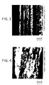
- Table 1 shows various physical properties of the carbon fibers thus obtained together with their crystal fibril thickness fluctuations observed with TEM, and Fig. 3 shows their TEM dark field image.
- Table 1 Fiber diameter ( ⁇ m) 9.8 Tensile strength (kg/mm2) 364 Tensile elastic modulus (ton/mm2) 52 Tensile elongation (%) 0.70 Compressive strength (kg/mm2) 135 Fibril thickness Average ( ⁇ ) 350 Distribution range ( ⁇ ) 110 to 680 Flucutations in fiber axis direction (%) ⁇ 3 to ⁇ 18 ( ⁇ 8.3 in average)
- the carbon fibers according to the invention attain as high compressive strength as 135 kg/mm2 with a tensile elastic modulus of 52 ton/mm2.
- the prior art product has a compressive strength of about 75 kg/mm2 with a tensile elastic modulus of 50 ton/mm2, and thus according to the invention it is possible to extremely improve the compressive strength.
- the average thickness Lav. of crystal fibriles obtained from Fig. 3 is 350 ⁇ .
- the thickness of the fibriles is distributed in a range of 110 to 680 ⁇ and in a range of 30 to 200 % of the average thickness (i.e., in a range of 105 to 700 ⁇ ).
- the fibril thickness fluctuation percentage in the fiber axis direction is within ⁇ 20 % and ⁇ 8.3 % in the average. Thus, the crystal structure is very uniform.
- the fibril thickness fluctuation percentage is with respect to the average value of one fibril.
- Example 1 The liquid crystal pitch A in Example 1 was used and spun at a temperature of 298 °C with a nozzle 0.3 mm in diameter while applying a shear of 1.2 kg/cm2 in a single stage, thus obtaining pitch fibers with a diameter of about 13 ⁇ m.
- the pitch fibers were then oxidatively stabilized in under the same condition as in Example 1 and then carbonized in an inert gas atmosphere at a temperature of 2,200 °C to obtain the resultant carbon fibers.
- Table 2 shows the physical properties of the carbon fibers thus obtained together with the crystal fibril thickness fluctuations observed with TEM.
- Table 2 Fiber diameter ( ⁇ m) 9.7 Tensile strength (kg/mm2) 302 Tensile elastic modulus (ton/mm2) 51 Tensile elongation (%) 0.59 Compressive strength (kg/mm2) 83 Fibril thickness Average ( ⁇ ) 520 Distribution range ( ⁇ ) 110 to 1,400 Flucutations in fiber axis direction (%) ⁇ 5 to ⁇ 40 ( ⁇ 25 in average)
- the pitch fibers were spun by the application of single stage shear spinning, the obtained carbon fibers has a low compressive strength of 83 kg/mm2 although the tensile elastic modulus is as high as 51 ton/mm2 as shown in Table 2.
- the average thickness of the crystal fibriles is 520 ⁇
- the fibril thickness ranges from 100 to 1,400 ⁇ , which is a wide range exceeding the range of 30 to 200 % of the average thickness (i.e., the range of 156 to 1,040 ⁇ ).
- the fibril thickness fluctuation percentage in the fiber axis direction reaches ⁇ 40 %, and the average value thereof is ⁇ 25 %. That is, the crystal structure lacks uniformity.
- liquid crystal pitch B A liquid crystal pitch with an optically anisotropic phase content of 100 %, a softening temperature of 285 °C and a molecular weight distribution range of 300 to 10,000 (referred to as liquid crystal pitch B) was used and spun at a temperature of 295 °C by the application of two stage high shear spinning as in Example 1 with the same nozzle as therein by setting the shear to 20 and 10 kg/cm2 in the respective first and second stages, thus obtaining pitch fibers with the diameters of about 13 ⁇ m.
- the pitch fibers were then ocidatively stabilized in an acidic atmosphere and then sintered in an inert gas atmosphere at 2,200 °C to obtain carbon fibers.
- Table 3 shows the physical properties of the carbon fibers obtained together with crystal fibril thickness fluctuations observed with TEM, and Fig. 4 shows a TEM dark field image of fibriles.
- Table 3 Fiber diameter ( ⁇ m) 9.9 Tensile strength (kg/mm2) 333 Tensile elastic modulus (ton/mm2) 50 Tensile elongation (%) 0.67 Compressive strength (kg/mm2) 80 Fibril thickness Average ( ⁇ ) 650 Distribution range ( ⁇ ) 110 to 1,800 Flucutations in fiber axis direction (%) ⁇ 8 to ⁇ 70 ( ⁇ 45 in average)
- the pitch fibers were spun by the application of two stage shear spinning, because the pitch of the wide molecular weight distribution range was used, the compressive strength of the obtained carbon fibers is as low as 80 kg/mm2 with a tensile elastic modulus of 50 ton/mm2 as shown in Table 3.
- the average thickness Lav. of the crystal fibriles is 650 ⁇
- the fibril thickness ranges from 100 to 1,800 ⁇ , which is a wide range exceeding the range of 30 to 200 % of the average thickness (i.e., the range of 195 to 1,300 ⁇ ).
- the fibril thickness fluctuation percentage in the fiber axis direction reaches ⁇ 70 %, and the average value thereof is ⁇ 45 %.
- the crystal structure is therefore extremely non-uniform.
Landscapes
- Chemical & Material Sciences (AREA)
- Chemical Kinetics & Catalysis (AREA)
- General Chemical & Material Sciences (AREA)
- Engineering & Computer Science (AREA)
- Textile Engineering (AREA)
- Inorganic Fibers (AREA)
- Working-Up Tar And Pitch (AREA)
Applications Claiming Priority (2)
| Application Number | Priority Date | Filing Date | Title |
|---|---|---|---|
| JP196399/92 | 1992-06-30 | ||
| JP4196399A JPH0617320A (ja) | 1992-06-30 | 1992-06-30 | 高圧縮強度ピッチ系炭素繊維 |
Publications (2)
| Publication Number | Publication Date |
|---|---|
| EP0577408A2 true EP0577408A2 (de) | 1994-01-05 |
| EP0577408A3 EP0577408A3 (de) | 1994-02-16 |
Family
ID=16357223
Family Applications (1)
| Application Number | Title | Priority Date | Filing Date |
|---|---|---|---|
| EP19930305113 Withdrawn EP0577408A2 (de) | 1992-06-30 | 1993-06-30 | Kohlenstoff-Faser mit hoher Druckfestigkeit aus Pech |
Country Status (3)
| Country | Link |
|---|---|
| US (1) | US5395607A (de) |
| EP (1) | EP0577408A2 (de) |
| JP (1) | JPH0617320A (de) |
Cited By (1)
| Publication number | Priority date | Publication date | Assignee | Title |
|---|---|---|---|---|
| EP2191982A1 (de) * | 2008-12-01 | 2010-06-02 | Sumitomo Rubber Industries, Ltd. | Gummizusammensetzung für eine Seitenwandverstärkungsschicht oder eine Seitenwand, und Reifen |
Families Citing this family (1)
| Publication number | Priority date | Publication date | Assignee | Title |
|---|---|---|---|---|
| TW200925344A (en) * | 2007-12-12 | 2009-06-16 | Everest Textile Co Ltd | Electric heating fabric device |
Family Cites Families (8)
| Publication number | Priority date | Publication date | Assignee | Title |
|---|---|---|---|---|
| DE2818528A1 (de) * | 1978-04-27 | 1979-10-31 | Erich Prof Dr Fitzer | Kohlenstoffkoerper mit ausgezeichneter mikrostruktur |
| US4504454A (en) * | 1983-03-28 | 1985-03-12 | E. I. Du Pont De Nemours And Company | Process of spinning pitch-based carbon fibers |
| DE3584119D1 (de) * | 1984-06-22 | 1991-10-24 | Toray Industries | Kohlenstoffasern mit sehr hoher zugfestigkeit. |
| US4775589A (en) * | 1985-07-02 | 1988-10-04 | Nippon Steel Cporporation | Coaltar pitch based carbon fiber having high Young's modulus |
| JPH0660451B2 (ja) * | 1987-06-05 | 1994-08-10 | 株式会社ペトカ | ピッチ系黒鉛繊維の製造方法 |
| JPH01124629A (ja) * | 1987-11-06 | 1989-05-17 | Toray Ind Inc | 高い圧縮強度を有する黒鉛繊維 |
| JPH0742615B2 (ja) * | 1988-03-28 | 1995-05-10 | 東燃料株式会社 | 高強度、高弾性率のピッチ系炭素繊維 |
| DE3827629A1 (de) * | 1988-08-16 | 1990-03-15 | Hoechst Ag | Verfahren und vorrichtung zur oberflaechenvorbehandlung von ein- oder mehrschichtigem formmaterial mittels einer elektrischen koronaentladung |
-
1992
- 1992-06-30 JP JP4196399A patent/JPH0617320A/ja active Pending
-
1993
- 1993-06-25 US US08/082,691 patent/US5395607A/en not_active Expired - Fee Related
- 1993-06-30 EP EP19930305113 patent/EP0577408A2/de not_active Withdrawn
Cited By (1)
| Publication number | Priority date | Publication date | Assignee | Title |
|---|---|---|---|---|
| EP2191982A1 (de) * | 2008-12-01 | 2010-06-02 | Sumitomo Rubber Industries, Ltd. | Gummizusammensetzung für eine Seitenwandverstärkungsschicht oder eine Seitenwand, und Reifen |
Also Published As
| Publication number | Publication date |
|---|---|
| US5395607A (en) | 1995-03-07 |
| JPH0617320A (ja) | 1994-01-25 |
| EP0577408A3 (de) | 1994-02-16 |
Similar Documents
| Publication | Publication Date | Title |
|---|---|---|
| EP3168334B1 (de) | Kohlenstofffaserbündel und verfahren zur herstellung davon | |
| Gallego et al. | Structure–property relationships for high thermal conductivity carbon fibers | |
| EP0057108B1 (de) | Verfahren zur Herstellung von kohlenstoffhaltigem, optisch anisotropen Pech | |
| EP0031707A2 (de) | Verfahren zur Herstellung von Kohlenstoffasern | |
| JPS6315376B2 (de) | ||
| CN116419994A (zh) | 用于纺丝成碳制品的沥青组合物及其相关方法 | |
| US4534850A (en) | Optically antisotropic carbonaceous pitch | |
| EP0577408A2 (de) | Kohlenstoff-Faser mit hoher Druckfestigkeit aus Pech | |
| EP0296396B1 (de) | Auf Mesaphasenpech basierende Kohlenstoffasern | |
| US4066737A (en) | Method for making isotropic carbon fibers | |
| CA1326933C (en) | Process for producing pitch for carbon materials | |
| US5968435A (en) | Process for manufacturing pitch-type carbon fiber | |
| JPH026628A (ja) | ピッチ糸炭素繊維の製造法 | |
| EP0524746B1 (de) | Optisch anisotropes Pech für die Herstellung von Kohlenstoffasern mit hoher Kompressivfestigkeit | |
| Bermudez | Anomalous Effect of Spinning Conditions on the Mechanical and Transport Properties of Mesophase Pitch-Based Carbon Fibers | |
| EP0378187A2 (de) | Pech für Kohlefasern, Verfahren zu dessen Herstellung und Verfahren zur Herstellung von Kohlefasern mit Verwendung dieses Pechs | |
| KR880002096B1 (ko) | 핏치를 사용하는 탄소섬유의 제조방법 | |
| JJ et al. | An evaluation of naphthalene-based mesophase as a carbon fiber precursor | |
| JPS61186520A (ja) | ピツチ系炭素繊維の製造方法 | |
| JPH04257321A (ja) | 高引張弾性率、高圧縮強度ピッチ系炭素繊維の製造方法 | |
| JPH05287618A (ja) | 高弾性率、高圧縮強度ピッチ系炭素繊維及びその製造方法 | |
| JPH0663135B2 (ja) | ピツチ系炭素繊維の製造方法 | |
| JP3164704B2 (ja) | ピッチ系高圧縮強度炭素繊維の製造方法 | |
| JPH0811844B2 (ja) | ピッチ系炭素繊維の製造方法 | |
| JP3055295B2 (ja) | ピッチ系炭素繊維とその製造方法 |
Legal Events
| Date | Code | Title | Description |
|---|---|---|---|
| PUAI | Public reference made under article 153(3) epc to a published international application that has entered the european phase |
Free format text: ORIGINAL CODE: 0009012 |
|
| PUAL | Search report despatched |
Free format text: ORIGINAL CODE: 0009013 |
|
| AK | Designated contracting states |
Kind code of ref document: A2 Designated state(s): DE FR GB |
|
| AK | Designated contracting states |
Kind code of ref document: A3 Designated state(s): DE FR GB |
|
| RIN1 | Information on inventor provided before grant (corrected) |
Inventor name: HINO, TAKASHI, C/O TONEN CORPORATION Inventor name: MURAKAMI, KAZUYUKI, C/OTONEN CORPORATION CORPORAT Inventor name: NAITO, TSUTOMO, C/O TONEN CORPORATION CORPORATE Inventor name: TOSHIMA, HIROSHI, C/O TONEN CORPORATION CORPORATE |
|
| RIN1 | Information on inventor provided before grant (corrected) |
Inventor name: HINO, TAKASHI, C/O TONEN CORPORATION Inventor name: MURAKAMI, KAZUYUKI, C/OTONEN CORPORATION CORPORAT Inventor name: NAITO, TSUTOMU, C/O TONEN CORPORATION CORPORATE Inventor name: TOSHIMA, HIROSHI, C/O TONEN CORPORATION CORPORATE |
|
| 17P | Request for examination filed |
Effective date: 19940715 |
|
| 17Q | First examination report despatched |
Effective date: 19970505 |
|
| STAA | Information on the status of an ep patent application or granted ep patent |
Free format text: STATUS: THE APPLICATION IS DEEMED TO BE WITHDRAWN |
|
| 18D | Application deemed to be withdrawn |
Effective date: 19971118 |