EP0576539B1 - Alkaline cell - Google Patents
Alkaline cell Download PDFInfo
- Publication number
- EP0576539B1 EP0576539B1 EP92907882A EP92907882A EP0576539B1 EP 0576539 B1 EP0576539 B1 EP 0576539B1 EP 92907882 A EP92907882 A EP 92907882A EP 92907882 A EP92907882 A EP 92907882A EP 0576539 B1 EP0576539 B1 EP 0576539B1
- Authority
- EP
- European Patent Office
- Prior art keywords
- anode
- cell
- metal
- collector
- volume
- Prior art date
- Legal status (The legal status is an assumption and is not a legal conclusion. Google has not performed a legal analysis and makes no representation as to the accuracy of the status listed.)
- Expired - Lifetime
Links
- 229910052751 metal Inorganic materials 0.000 claims abstract description 49
- 239000002184 metal Substances 0.000 claims abstract description 49
- HCHKCACWOHOZIP-UHFFFAOYSA-N Zinc Chemical compound [Zn] HCHKCACWOHOZIP-UHFFFAOYSA-N 0.000 claims abstract description 37
- 239000011701 zinc Substances 0.000 claims abstract description 37
- 229910052725 zinc Inorganic materials 0.000 claims abstract description 31
- QSHDDOUJBYECFT-UHFFFAOYSA-N mercury Chemical compound [Hg] QSHDDOUJBYECFT-UHFFFAOYSA-N 0.000 claims description 16
- 229910052753 mercury Inorganic materials 0.000 claims description 16
- NUJOXMJBOLGQSY-UHFFFAOYSA-N manganese dioxide Chemical compound O=[Mn]=O NUJOXMJBOLGQSY-UHFFFAOYSA-N 0.000 claims description 13
- 239000006260 foam Substances 0.000 claims description 12
- 239000002245 particle Substances 0.000 claims description 11
- 239000000463 material Substances 0.000 claims description 7
- 239000006262 metallic foam Substances 0.000 claims description 7
- RYGMFSIKBFXOCR-UHFFFAOYSA-N Copper Chemical compound [Cu] RYGMFSIKBFXOCR-UHFFFAOYSA-N 0.000 claims description 6
- 229910052802 copper Inorganic materials 0.000 claims description 6
- 239000010949 copper Substances 0.000 claims description 6
- 239000003792 electrolyte Substances 0.000 claims description 6
- 229910052738 indium Inorganic materials 0.000 claims description 5
- APFVFJFRJDLVQX-UHFFFAOYSA-N indium atom Chemical compound [In] APFVFJFRJDLVQX-UHFFFAOYSA-N 0.000 claims description 5
- 229910045601 alloy Inorganic materials 0.000 claims description 3
- 239000000956 alloy Substances 0.000 claims description 3
- ATJFFYVFTNAWJD-UHFFFAOYSA-N Tin Chemical compound [Sn] ATJFFYVFTNAWJD-UHFFFAOYSA-N 0.000 claims description 2
- 230000004323 axial length Effects 0.000 claims description 2
- 229910052718 tin Inorganic materials 0.000 claims description 2
- 239000003112 inhibitor Substances 0.000 description 6
- 229960001296 zinc oxide Drugs 0.000 description 6
- XLOMVQKBTHCTTD-UHFFFAOYSA-N zinc oxide Inorganic materials [Zn]=O XLOMVQKBTHCTTD-UHFFFAOYSA-N 0.000 description 6
- 239000000758 substrate Substances 0.000 description 5
- 239000007789 gas Substances 0.000 description 4
- 229910001369 Brass Inorganic materials 0.000 description 3
- 229910019142 PO4 Inorganic materials 0.000 description 3
- 239000010951 brass Substances 0.000 description 3
- 150000002739 metals Chemical class 0.000 description 3
- 239000010452 phosphate Substances 0.000 description 3
- -1 phosphate ester Chemical class 0.000 description 3
- 239000011148 porous material Substances 0.000 description 3
- 230000035939 shock Effects 0.000 description 3
- UFHFLCQGNIYNRP-UHFFFAOYSA-N Hydrogen Chemical compound [H][H] UFHFLCQGNIYNRP-UHFFFAOYSA-N 0.000 description 2
- WHXSMMKQMYFTQS-UHFFFAOYSA-N Lithium Chemical compound [Li] WHXSMMKQMYFTQS-UHFFFAOYSA-N 0.000 description 2
- 239000011149 active material Substances 0.000 description 2
- 230000000052 comparative effect Effects 0.000 description 2
- 238000000034 method Methods 0.000 description 2
- 239000000203 mixture Substances 0.000 description 2
- 230000035945 sensitivity Effects 0.000 description 2
- 229910000906 Bronze Inorganic materials 0.000 description 1
- OKTJSMMVPCPJKN-UHFFFAOYSA-N Carbon Chemical compound [C] OKTJSMMVPCPJKN-UHFFFAOYSA-N 0.000 description 1
- XUIMIQQOPSSXEZ-UHFFFAOYSA-N Silicon Chemical compound [Si] XUIMIQQOPSSXEZ-UHFFFAOYSA-N 0.000 description 1
- 239000010974 bronze Substances 0.000 description 1
- 230000001413 cellular effect Effects 0.000 description 1
- 238000000576 coating method Methods 0.000 description 1
- 239000004020 conductor Substances 0.000 description 1
- KUNSUQLRTQLHQQ-UHFFFAOYSA-N copper tin Chemical compound [Cu].[Sn] KUNSUQLRTQLHQQ-UHFFFAOYSA-N 0.000 description 1
- 230000000694 effects Effects 0.000 description 1
- 230000008030 elimination Effects 0.000 description 1
- 238000003379 elimination reaction Methods 0.000 description 1
- 230000007613 environmental effect Effects 0.000 description 1
- 239000003349 gelling agent Substances 0.000 description 1
- 239000010439 graphite Substances 0.000 description 1
- 229910002804 graphite Inorganic materials 0.000 description 1
- 230000005484 gravity Effects 0.000 description 1
- 229910052744 lithium Inorganic materials 0.000 description 1
- 229910001947 lithium oxide Inorganic materials 0.000 description 1
- 238000007747 plating Methods 0.000 description 1
- 238000007493 shaping process Methods 0.000 description 1
- 229910052710 silicon Inorganic materials 0.000 description 1
- 239000010703 silicon Substances 0.000 description 1
- 239000010935 stainless steel Substances 0.000 description 1
- 229910001220 stainless steel Inorganic materials 0.000 description 1
- 239000000725 suspension Substances 0.000 description 1
- 239000011135 tin Substances 0.000 description 1
- XLYOFNOQVPJJNP-UHFFFAOYSA-N water Substances O XLYOFNOQVPJJNP-UHFFFAOYSA-N 0.000 description 1
- 238000003466 welding Methods 0.000 description 1
Images

Classifications
-
- H—ELECTRICITY
- H01—ELECTRIC ELEMENTS
- H01M—PROCESSES OR MEANS, e.g. BATTERIES, FOR THE DIRECT CONVERSION OF CHEMICAL ENERGY INTO ELECTRICAL ENERGY
- H01M6/00—Primary cells; Manufacture thereof
- H01M6/04—Cells with aqueous electrolyte
- H01M6/06—Dry cells, i.e. cells wherein the electrolyte is rendered non-fluid
- H01M6/08—Dry cells, i.e. cells wherein the electrolyte is rendered non-fluid with cup-shaped electrodes
-
- H—ELECTRICITY
- H01—ELECTRIC ELEMENTS
- H01M—PROCESSES OR MEANS, e.g. BATTERIES, FOR THE DIRECT CONVERSION OF CHEMICAL ENERGY INTO ELECTRICAL ENERGY
- H01M4/00—Electrodes
- H01M4/02—Electrodes composed of, or comprising, active material
- H01M4/64—Carriers or collectors
- H01M4/66—Selection of materials
- H01M4/661—Metal or alloys, e.g. alloy coatings
-
- H—ELECTRICITY
- H01—ELECTRIC ELEMENTS
- H01M—PROCESSES OR MEANS, e.g. BATTERIES, FOR THE DIRECT CONVERSION OF CHEMICAL ENERGY INTO ELECTRICAL ENERGY
- H01M4/00—Electrodes
- H01M4/02—Electrodes composed of, or comprising, active material
- H01M4/64—Carriers or collectors
- H01M4/70—Carriers or collectors characterised by shape or form
- H01M4/80—Porous plates, e.g. sintered carriers
-
- Y—GENERAL TAGGING OF NEW TECHNOLOGICAL DEVELOPMENTS; GENERAL TAGGING OF CROSS-SECTIONAL TECHNOLOGIES SPANNING OVER SEVERAL SECTIONS OF THE IPC; TECHNICAL SUBJECTS COVERED BY FORMER USPC CROSS-REFERENCE ART COLLECTIONS [XRACs] AND DIGESTS
- Y02—TECHNOLOGIES OR APPLICATIONS FOR MITIGATION OR ADAPTATION AGAINST CLIMATE CHANGE
- Y02P—CLIMATE CHANGE MITIGATION TECHNOLOGIES IN THE PRODUCTION OR PROCESSING OF GOODS
- Y02P70/00—Climate change mitigation technologies in the production process for final industrial or consumer products
- Y02P70/50—Manufacturing or production processes characterised by the final manufactured product
Definitions
- the present invention relates to a high power primary alkaline cell having a powdered zinc anode.
- the cell comprises an improved anode current collector made from a foraminous metal. Such a collector permits power to be drawn from such cells which can not otherwise be drawn when conventional collectors are used.
- Alkaline zinc/manganese dioxide cells have been commercially available for over twenty years. Generally, these cells have a "bobbin design" wherein the manganese dioxide cathode is annularly shaped and has its outer wall in contact with the inner wall of the cell casing. The central cavity of the annulus is lined with an appropriate separator material, and a gelled mixture of the powdered zinc anode and an aqueous electrolyte is contained within the separator lined cavity. The open end of the cell casing is sealed by a circular closure member, and a nail shaped anode collector passes through said closure member into the zinc anode.
- a nail-shaped anode collector works well for many applications. This is evidenced by the fact that since alkaline cells became available over twenty years ago a nail-type collector has been used by most battery manufacturers (one manufacturer has used a flat metal sheet bent into a semi-circle in "C” and "D" size cells). However, it has been discovered that replacing a nail-type collector with a foraminous metal collector increases the energy available at high power drains, e.g. in excess of 1 watt, up to ten times as much, in some applications, as is available using a nail. Examples of foraminous metals includes, but is not limited to metal foam, metal felt, expanded metal, woven metal, and knitted metal mesh. Such an increase in the power capability of a primary alkaline cell not only improves the usefulness of such cells in present applications but also opens up new applications which could not be satisfied by presently available alkaline cells.
- Anode collectors of the present invention can be made with about the same metal content as presently used nails so that the actual volume taken up inside the anode is no greater than a nail.
- anode collectors of the present invention can be made which take up less actual volume than nail-type collectors so that more zinc can be added to the anode.
- the distribution of the foraminous metal is throughout a greater volume of the anode than a nail.
- the collectors of the present invention can extend throughout substantially the entire anode volume while only taking up the same actual volume as a nail.
- a primary zinc/manganese dioxide cell does not have the zinc particles fixed to a substrate. Rather, the electrolyte and the anode particles are dispensed into the anode cavity and a current collector is inserted thereafter. This process works best if the zinc/electrolyte mixture has some fluid-like properties. Once the zinc is dispensed into the cell it is desirable to keep the particles from settling due to gravity since this would shorten the height of the anode and detrimentally effect cell performance. Therefore, the zinc anode is often in the form of a gel or suspension containing the individual zinc particles and a gellant material. Electrical continuity throughout the anode depends on the particle to particle contact between the individual particles. Electrical continuity is also enhanced in presently available alkaline cells by the presence of mercury which is added to the anode for the reasons described immediately below.
- Zinc has a tendency to react with the aqueous electrolyte and form hydrogen gas. Gas build-up within a cell is undesirable for obvious reasons.
- One solution to this problem is to amalgamate the zinc with mercury.
- Amalgamated zinc has a lesser tendency to react with water than pure zinc whereby hydrogen gas generation is controlled at acceptable levels.
- due to the environmental concerns over used alkaline cells being disposed of in land fills there has been a recent trend toward reducing the amount of mercury or eliminating it altogether. The reduction or elimination of mercury is not without its problems. Reduction of the mercury content to 0.5% or less, by weight, of the anode results in an increased shock sensitivity of the voltage of an alkaline cell during discharge. Attempts have been made to overcome the shock sensitivity problem described above.
- U.S. patents Nos. 4,939,048 and 4,942,101 disclose the use of anode collectors which are modified versions of the nail-type collector described above.
- the present invention cures the voltage instability problem associated with low mercury levels described above in addition to increasing the energy available at high power drains.
- eliminating mercury from the anode in cells made in accordance with the present invention improves the power capability under high rate discharge.
- the zinc anode contains no mercury whatsoever.
- Such embodiment preferably also includes a gas inhibitor such as those disclosed in U.S. patent No. 4,195,120 or any of the other well known inhibitors.
- cell 10 comprises cylindrical casing 12 having cathode 14 disposed therein and contacting the inner wall of said casing.
- Cathode 14 is a porous, annularly shaped structure comprising manganese dioxide and graphite, which structure is permeated by electrolyte.
- the central cavity of cathode 14 is lined with an appropriate separator material and a gelled zinc anode 16 comprising discrete zinc particles fills the separator lined cavity.
- anode collector 20 is made from a foraminous metal.
- a metal tab 21 has one end welded to collector 20 and the other end welded to rivet 23. Rivet 23 passes through closure member 22 and contacts metal cover 24 whereby electrical connection of the anode to the outside negative contact 24 is achieved.
- anode collector 20 is made from a metal foam material, such as that made by the process disclosed in U.S. patent-No. 4,882,22.
- the metal foams are preferably at least 80% porous, more preferably at least 90% porous, and most preferably at least 95% porous.
- the size of the pores will desirably range from about 0.025 cm (0.01 inch) to about 0.25 cm (0.1 inch).
- the cylindrically shaped foam anode collector has a diameter of at least about 50% of the diameter of the zinc anode and a length corresponding to a major portion of the axial length of the cavity.
- the collectors are generally prepared from a flat foam sheet. This is readily achieved for "AA" size cells, which have an anode diameter of about 0.89 cm (0.35 inch), by forming the foam cylinders from a sheet about 0.8 cm (0.3 inch) thick. However, for larger cells such as "D" cells, a collector such as the one shown in FIG. 2A can be used. The reason for this is that foam metal sheets having a thickness of about 2.3 cm (0.9 inch) are not readily available. Therefore, by taking a thinner foam sheet and folding, coiling, or otherwise shaping it into a more or less cylindrical shape, the desired current collector is obtained.
- FIG. 2B Another embodiment of the anode collector is shown in FIG. 2B.
- Anode collector 20B is formed by taking a rectangularly shaped piece of expanded metal and coiling it to form a cylinder.
- the expanded metal can be loosely coiled so that there are small gaps within the cylindrical structure. This embodiment imparts similar high rate capability to a cell as obtained by a cylinder of foam.
- the foraminous metal is preferably made from a material which is stable in the cell environment.
- Preferred materials include, but are not limited to, copper, silicon bronze, brass, tin, indium, lead, and alloys of these.
- the foraminous metal could be made of any metal which has a surface plating of one of the above preferred metals.
- any of the well known coatings for anode conductors which inhibit gassing in alkaline cells can also be used on the collectors of the present invention.
- the actual volume occupied by an anode collector of the present invention preferably will not be greater than the volume of the collectors which are presently being used.
- the volume percent of the anode cavity which a collector occupies in commercially available alkaline cells is generally less than about 1.5%.
- the actual volume of the collector could be increased to as high as 5% of the anode volume without detrimentally effecting the cell performance since at high power drains all of the zinc is not utilized.
- the "apparent volume” of anode collectors made in accordance with the present invention will exceed the actual volume.
- the term "apparent volume” means the volume of the shape which follows the contours of the outermost surfaces of the collector, from which large openings or gaps, such as those which would result from forming the collector from a metal network which originally is in a different shape, such as a flat sheet, are subtracted. In determining the apparent volume the pores or interstices of the metal network are ignored.
- the maximum apparent volume for the collector is about 100% of the anode volume. However, the apparent volume will be less than this if the collector is to be inserted into the cavity after it is filled with the powdered zinc anode.
- An anode collector of the present invention is a cylinder made from a foraminous metal which contains about the same amount of metal as a typical nail-type collector (only that part of the nail which penetrates into the anode) but which has an apparent volume of the portion contained within the anode which is no greater than the anode volume.
- a collector will necessarily have a high degree of porosity in order to have no more metal than a nail and also have a high apparent volume.
- An indicator of the porosity is the ratio of the apparent volume of the collector, V app , to the actual volume of metal in the collector, V act .
- a non-porous metal collector, such as a nail would have a ratio of V app /V act equal to 1 since the apparent volume would equal the actual volume.
- a foraminous metal will always have a ratio of V app /V act greater than 1.
- a collector made of metal foam in the shape of a cylinder the size of a zinc anode for a AA cell and having the same metal content as a presently used nail has a ratio of V app /V act of about 60.
- a piece of expanded metal made from a thin sheet stock and having small openings could have a ratio of V app /V act as low as 5, and still be useful in accordance with the invention. It is preferred that the ratio is at least about 10, and in a most preferred embodiment, especially where high drain rates are desired, the ratio should be in excess of 20.
- Zone "A” has a radius of 0.33r (r- the radius of the zinc anode)
- zone “B” includes zone “A” and has a radius of 0.67r
- zone “C” includes both zones "A” and "B” and has a radius equal to r.
- zone A occupies about 11% of the anode volume
- zone B about 45% of the anode volume
- zone C about 100% of the anode volume.
- Nail-type collectors reside wholly within zone A.
- the collectors of the present invention preferably extend at least to the outer portion of zone "B” and, more preferably, extend beyond said outer portion. It is believed that extending the metal of the collector outwardly beyond zone "B" improves the collection of electrons from the zinc in this region during discharge which in turn allows greater power to be drawn from the cell.
- a gelled zinc anode is used without any mercury present but contains 50 ppm of a phosphate ester gas inhibitor (RA600, GAF Corp.) and the zinc particles contain 250 ppm indium.
- RA600 phosphate ester gas inhibitor
- the cells are divided into four groups of 8.
- the cells of one group are each discharged at 3.9 ohms
- the cells of the second group are each discharged at 1 ohm
- the cells of the third group are each discharged at 0.5 ohm
- the cells of the fourth group are each discharged at 0.25 ohm.
- a cut-off voltage of 0.9 volts the power obtained from each cell at the 3.9 ohms discharge is about 0.5 watt
- the power obtained from each cell at the 1 ohm discharge is about 1 watt
- the power obtained from each at the 0.5 ohm discharge is about 2 watts
- the power obtained from each cell at the 0.25 ohm discharge is about 4 watts.
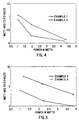
- the average watt-hours obtained from each group of cells is shown in FIG. 4 plotted against the power drains given above.
- Each cell has an anode collector comprising a cylinder of copper foam.
- the foam has about 20 pores per inch and the cylinder is about 0.64 cm (0.25 inch) in diameter and 4 cm (1.6 inch) long.
- the apparent volume is about 50% of the anode volume.
- the cylinder weighs about 0.25 grams and has an actual volume which is about 1% of the anode volume. The ratio of the apparent volume to the actual volume is about 50. Electrical connection to the foam cylinder is achieved by a nail which penetrates through the cell cover and contacts the upper portion of the foam.
- the cells are divided into four groups of eight. These groups are discharged as described above. The average watt-hours obtained from each group is shown in FIG. 4 plotted against the power drain.
- the cells of the present invention deliver 1.1 times the energy of the prior art cells, at the 1 watt drain they deliver 1.2 times the energy of the prior art cells; at the 2 watt drain they deliver 2.3 times the energy of prior art cells, and at the 4 watt drain they deliver 2 times the energy of prior art cells.
- Eighteen “D” size zinc/manganese dioxide cells are built having a brass nail as the anode collector.
- the nail occupies about 0.6% of the volume of the anode cavity.
- a gelled zinc anode is used without any mercury present but contains 50 ppm of a phosphate ester gas inhibitor (RA600) and the zinc particles contain 250 ppm indium.
- RA600 phosphate ester gas inhibitor
- the cells are divided into three groups of six.
- the cells of one group are each discharged at 1 ohm
- the cells of the second group are each discharged at 0.5 ohm
- the cells of the third group are each discharged at 0.25 ohms.
- the power delivered by each cell under these loads is about the same as described in the previous two examples.
- the average watt-hours obtained to a 0.9 volt cut-off from each group of cells is shown in FIG. 5 plotted against the power drain.
- Each cell has an anode collector comprising a piece of copper expanded metal formed into a cylinder.
- the expanded metal used to form the cylinder is 4 cm (1.6 inches) wide and 13.75 cm (5.5 inches) long with a thickness of 0.032 cm (0.012 inch) (Delker Corp., #5Cu 7-125) giving an apparent volume which is about 11% of the anode volume.
- the expanded metal is loosely coiled into a cylindrical shape having a diameter of about 1.6 cm (0.6 inch) and a height of 4 cm (1.6 inches) so that the collector extends into the outer portion of zone "B" (see FIG. 3).
- each cylinder is about 1% of the volume of the anode so that V app /V act is about 11.
- a copper tab is welded to one end of each cylinder. Attachment to the cover is achieved by welding the other end of the tab to a rivet located in the center of the cell cover.
- the cells are divided into three groups of six. These groups are discharged as described above. The average watt-hours obtained from each group is shown in FIG. 5 plotted against the power drain. At the 1 watt drain the cells of the present invention deliver about 2 times the energy of the prior art cells; at the 2 watt drain they deliver over 3 times the energy of prior art cells, and at the 4 watt drain they deliver over 10 times the energy of prior art cells.
- Alkaline cells having an anode collector in accordance with the present invention deliver significantly more energy at high power drains without increasing the amount of active materials.
- the improved high power capability allows cells made in accordance with the present invention to be used for powering cellular telephones, lap top computers, camcorders, and other devices which previously could not use primary alkaline cells.
Landscapes
- Chemical & Material Sciences (AREA)
- Chemical Kinetics & Catalysis (AREA)
- Electrochemistry (AREA)
- General Chemical & Material Sciences (AREA)
- Engineering & Computer Science (AREA)
- Materials Engineering (AREA)
- Manufacturing & Machinery (AREA)
- Primary Cells (AREA)
- Battery Electrode And Active Subsutance (AREA)
- Cell Electrode Carriers And Collectors (AREA)
Applications Claiming Priority (3)
| Application Number | Priority Date | Filing Date | Title |
|---|---|---|---|
| US07/673,045 US5856040A (en) | 1991-03-21 | 1991-03-21 | Alkaline cell |
| US673045 | 1991-03-21 | ||
| PCT/US1992/001040 WO1992016978A1 (en) | 1991-03-21 | 1992-02-10 | Alkaline cell |
Publications (3)
| Publication Number | Publication Date |
|---|---|
| EP0576539A1 EP0576539A1 (en) | 1994-01-05 |
| EP0576539A4 EP0576539A4 (en) | 1994-12-07 |
| EP0576539B1 true EP0576539B1 (en) | 1996-11-27 |
Family
ID=24701101
Family Applications (1)
| Application Number | Title | Priority Date | Filing Date |
|---|---|---|---|
| EP92907882A Expired - Lifetime EP0576539B1 (en) | 1991-03-21 | 1992-02-10 | Alkaline cell |
Country Status (18)
| Country | Link |
|---|---|
| US (1) | US5856040A (pt) |
| EP (1) | EP0576539B1 (pt) |
| JP (1) | JP2993737B2 (pt) |
| KR (1) | KR100255115B1 (pt) |
| CN (1) | CN1042876C (pt) |
| AU (1) | AU664364B2 (pt) |
| BR (1) | BR9205794A (pt) |
| CA (1) | CA2100247C (pt) |
| DE (1) | DE69215505T2 (pt) |
| HK (1) | HK1004034A1 (pt) |
| IL (1) | IL100774A (pt) |
| MX (1) | MX9201213A (pt) |
| MY (1) | MY109932A (pt) |
| NZ (1) | NZ241969A (pt) |
| PT (1) | PT100270A (pt) |
| SG (1) | SG66282A1 (pt) |
| TW (1) | TW231379B (pt) |
| WO (1) | WO1992016978A1 (pt) |
Families Citing this family (20)
| Publication number | Priority date | Publication date | Assignee | Title |
|---|---|---|---|---|
| US6300004B1 (en) * | 1998-08-21 | 2001-10-09 | Eveready Battery Company, Inc. | Battery constructions having reduced collector assembly volume |
| US6150052A (en) * | 1998-10-19 | 2000-11-21 | Eveready Battery Company, Inc. | Electrode for an electrochemical cell including stacked disks |
| US6143446A (en) * | 1998-10-21 | 2000-11-07 | Duracell Inc. | Battery cathode |
| US6221527B1 (en) | 1998-12-01 | 2001-04-24 | Eveready Battery Company, Inc. | Electrode for an electrochemical cell including ribbons |
| WO2000059052A2 (en) * | 1999-03-29 | 2000-10-05 | The Gillette Company | Alkaline cell separator |
| US6483275B1 (en) | 1999-04-23 | 2002-11-19 | The Board Of Trustees Of The Univesity Of Illinois | Consumer battery having a built-in indicator |
| FR2796496A1 (fr) * | 1999-07-15 | 2001-01-19 | Cit Alcatel | Electrode au zinc pour generateur electrochimique a electrolyte alcalin |
| US6605383B1 (en) * | 2000-11-22 | 2003-08-12 | Eveready Battery Company, Inc. | Alkaline electrochemical cell having adhesive closure |
| US6627349B2 (en) | 2001-04-26 | 2003-09-30 | Eveready Battery Company, Inc. | Electrode for an electrochemical cell |
| US6673494B2 (en) | 2002-02-15 | 2004-01-06 | Alltrista Zinc Products, L.P. | Expanded zinc mesh anode |
| US20080166632A1 (en) * | 2003-08-18 | 2008-07-10 | Powergenix, Inc. | Method of manufacturing nickel zinc batteries |
| CN100521302C (zh) * | 2003-08-18 | 2009-07-29 | 鲍尔热尼系统公司 | 制造镍锌电池的方法 |
| US8703330B2 (en) * | 2005-04-26 | 2014-04-22 | Powergenix Systems, Inc. | Nickel zinc battery design |
| US20080268341A1 (en) * | 2007-03-14 | 2008-10-30 | Teck Cominco Metals Ltd. | High power batteries and electrochemical cells and methods of making same |
| US8236444B2 (en) * | 2007-03-27 | 2012-08-07 | Eveready Battery Company, Inc. | Electrochemical cell having low volume collector assembly |
| KR101536031B1 (ko) * | 2008-04-02 | 2015-07-10 | 파워지닉스 시스템즈, 인코포레이티드 | 네거티브 캔을 포함하는 원통형 니켈-아연 전지 |
| US20100068609A1 (en) * | 2008-09-15 | 2010-03-18 | Ultralife Corportion | Hybrid cell construction for improved performance |
| JP2011249287A (ja) * | 2010-05-31 | 2011-12-08 | Sumitomo Electric Ind Ltd | 電池用負極とその製造方法および一次電池 |
| US20160308219A1 (en) * | 2015-04-14 | 2016-10-20 | Intel Corporation | Randomly shaped three dimensional battery cell with shape conforming conductive covering |
| US10566582B2 (en) | 2016-06-23 | 2020-02-18 | Intel Corporation | Battery utilizing device cavity |
Family Cites Families (17)
| Publication number | Priority date | Publication date | Assignee | Title |
|---|---|---|---|---|
| US3219487A (en) * | 1962-06-06 | 1965-11-23 | Servel Inc | Perforated contact member for voltaic cell electrodes |
| US3510358A (en) * | 1967-11-02 | 1970-05-05 | Faat Khatovich Nabiullin | Primary alkaline cell |
| FR1604005A (pt) * | 1968-07-18 | 1971-06-28 | ||
| US4211829A (en) * | 1977-04-27 | 1980-07-08 | Compagnie Generale Des Etablissements Michelin | Process for assembling a porous membrane on a support and assembly produced in this manner |
| US4091178A (en) * | 1977-09-01 | 1978-05-23 | Union Carbide Corporation | Rechargeable alkaline MnO2 -zinc cell |
| US4175052A (en) * | 1978-03-31 | 1979-11-20 | Union Carbide Corporation | Alkaline-MnO2 cell having a zinc powder-gel anode containing P-N-V-P or PMA |
| JPS5532346A (en) * | 1978-08-28 | 1980-03-07 | Hitachi Maxell Ltd | Electrode |
| JPS5532345A (en) * | 1978-08-28 | 1980-03-07 | Hitachi Maxell Ltd | Manganese dioxide electrode |
| DE3026065A1 (de) * | 1980-07-10 | 1982-02-04 | Varta Batterie Ag, 3000 Hannover | Wiederaufladbares galvanisches element |
| US4777100A (en) * | 1985-02-12 | 1988-10-11 | Duracell Inc. | Cell corrosion reduction |
| GB2176474A (en) * | 1985-06-15 | 1986-12-31 | Tanabe Seiyaku Co | Thiazolidine derivatives |
| FR2634596B1 (fr) * | 1988-07-25 | 1990-10-26 | Cipel | Generateur electrochimique a electrolyte alcalin et a electrode negative de zinc |
| FR2634595B1 (fr) * | 1988-07-25 | 1995-07-28 | Cipel | Generateur electrochimique a electrolyte alcalin et a electrode negative de zinc |
| US5034291A (en) * | 1989-08-16 | 1991-07-23 | Rayovac Corporation | Aluminum compound additives to reduce zinc corrosion in anodes of electrochemical cells |
| US4992343A (en) * | 1989-08-17 | 1991-02-12 | Eveready Battery Company, Inc. | Lead-containing anode current collector for alkaline cells |
| CA2002348A1 (en) * | 1989-11-06 | 1991-05-06 | Klaus Tomantschger | Zinc anodes for alkaline galvanic cells and cells containing them |
| FR2680049A1 (fr) * | 1991-08-02 | 1993-02-05 | Sorapec | Realisation d'electrodes ou de collecteurs d'electrodes par projection a la flamme. |
-
1991
- 1991-03-21 US US07/673,045 patent/US5856040A/en not_active Expired - Lifetime
-
1992
- 1992-01-27 IL IL100774A patent/IL100774A/xx not_active IP Right Cessation
- 1992-02-10 KR KR1019930702818A patent/KR100255115B1/ko not_active IP Right Cessation
- 1992-02-10 EP EP92907882A patent/EP0576539B1/en not_active Expired - Lifetime
- 1992-02-10 SG SG1996007546A patent/SG66282A1/en unknown
- 1992-02-10 AU AU15345/92A patent/AU664364B2/en not_active Ceased
- 1992-02-10 JP JP4507271A patent/JP2993737B2/ja not_active Expired - Fee Related
- 1992-02-10 WO PCT/US1992/001040 patent/WO1992016978A1/en active IP Right Grant
- 1992-02-10 MY MYPI92000192A patent/MY109932A/en unknown
- 1992-02-10 DE DE69215505T patent/DE69215505T2/de not_active Expired - Lifetime
- 1992-02-10 BR BR9205794A patent/BR9205794A/pt not_active IP Right Cessation
- 1992-02-10 CA CA002100247A patent/CA2100247C/en not_active Expired - Fee Related
- 1992-02-22 TW TW081101309A patent/TW231379B/zh active
- 1992-03-16 NZ NZ241969A patent/NZ241969A/xx unknown
- 1992-03-19 MX MX9201213A patent/MX9201213A/es not_active IP Right Cessation
- 1992-03-20 PT PT100270A patent/PT100270A/pt not_active Application Discontinuation
- 1992-03-20 CN CN92101850A patent/CN1042876C/zh not_active Expired - Fee Related
-
1998
- 1998-04-15 HK HK98103116A patent/HK1004034A1/xx not_active IP Right Cessation
Also Published As
| Publication number | Publication date |
|---|---|
| AU1534592A (en) | 1992-10-21 |
| US5856040A (en) | 1999-01-05 |
| TW231379B (pt) | 1994-10-01 |
| BR9205794A (pt) | 1994-08-02 |
| CN1065555A (zh) | 1992-10-21 |
| DE69215505D1 (de) | 1997-01-09 |
| AU664364B2 (en) | 1995-11-16 |
| KR100255115B1 (ko) | 2000-05-01 |
| MX9201213A (es) | 1992-10-01 |
| HK1004034A1 (en) | 1998-11-13 |
| IL100774A0 (en) | 1992-09-06 |
| CA2100247C (en) | 1999-12-21 |
| MY109932A (en) | 1997-09-30 |
| EP0576539A4 (en) | 1994-12-07 |
| IL100774A (en) | 1997-07-13 |
| PT100270A (pt) | 1994-04-29 |
| JP2993737B2 (ja) | 1999-12-27 |
| EP0576539A1 (en) | 1994-01-05 |
| NZ241969A (en) | 1993-06-25 |
| CN1042876C (zh) | 1999-04-07 |
| JPH07502621A (ja) | 1995-03-16 |
| WO1992016978A1 (en) | 1992-10-01 |
| SG66282A1 (en) | 1999-07-20 |
| DE69215505T2 (de) | 1997-07-03 |
Similar Documents
| Publication | Publication Date | Title |
|---|---|---|
| EP0576539B1 (en) | Alkaline cell | |
| US4091178A (en) | Rechargeable alkaline MnO2 -zinc cell | |
| EP1790024A1 (en) | ALKALINE BATTERY WITH MnO<sb>2</sb>/NiOOH ACTIVE MATERIAL | |
| HUT77304A (hu) | Mangán-dioxid pozitív elektród újratölthető cellákhoz és ilyent tartalmazó cellák | |
| JP2993886B2 (ja) | アルカリ蓄電池用の陽極と陰極及びその製造方法 | |
| KR20020053807A (ko) | 재 충전식 니켈-아연 전지 | |
| CA1096443A (en) | Expanded zinc electrode for dry cells | |
| GB2080999A (en) | Dry cell and process for producing same | |
| US4403020A (en) | Electrochemical cell | |
| US5510204A (en) | Galvanic cell with an anode electrode that extends up to at least 80 perent of the height of the cathode electrode | |
| US3261714A (en) | Sealed dry cells having an ionization catalyst in the depolarizer | |
| US5984982A (en) | Electrochemical synthesis of cobalt oxyhydroxide | |
| US5356732A (en) | Alkaline storage cell activation method | |
| US3198668A (en) | Two layer zinc anode | |
| JP2004006258A (ja) | ニッケル−水素蓄電池用負極板およびその製造方法ならびにそれを用いたニッケル−水素蓄電池 | |
| JP2798753B2 (ja) | 非水電解液二次電池 | |
| JPH05242908A (ja) | 金属水素化物蓄電池 | |
| JP4067524B2 (ja) | ニッケル−水素蓄電池用負極板およびその製造方法ならびにそれを用いたニッケル−水素蓄電池 | |
| JP3025692B2 (ja) | 二次電池 | |
| JPH0620681A (ja) | 金属−水素アルカリ電池 | |
| JPH028419B2 (pt) | ||
| JP2023069444A (ja) | アルカリ電池 | |
| KR19980075539A (ko) | 전지용 극판 및 그 제조방법 | |
| JP2562651B2 (ja) | 非水電解液二次電池 | |
| JP2011513910A (ja) | 単3及び単4電池用のカソード |
Legal Events
| Date | Code | Title | Description |
|---|---|---|---|
| PUAI | Public reference made under article 153(3) epc to a published international application that has entered the european phase |
Free format text: ORIGINAL CODE: 0009012 |
|
| 17P | Request for examination filed |
Effective date: 19930909 |
|
| AK | Designated contracting states |
Kind code of ref document: A1 Designated state(s): BE DE FR GB IT |
|
| RIN1 | Information on inventor provided before grant (corrected) |
Inventor name: VERNHES, MICHEL J. Inventor name: TAYLOR, ALWYN H. Inventor name: NEWMAN, GERALD H. |
|
| A4 | Supplementary search report drawn up and despatched | ||
| AK | Designated contracting states |
Kind code of ref document: A4 Designated state(s): BE DE FR GB IT |
|
| 17Q | First examination report despatched |
Effective date: 19950803 |
|
| GRAG | Despatch of communication of intention to grant |
Free format text: ORIGINAL CODE: EPIDOS AGRA |
|
| RAP1 | Party data changed (applicant data changed or rights of an application transferred) |
Owner name: DURACELL INC. |
|
| GRAH | Despatch of communication of intention to grant a patent |
Free format text: ORIGINAL CODE: EPIDOS IGRA |
|
| GRAH | Despatch of communication of intention to grant a patent |
Free format text: ORIGINAL CODE: EPIDOS IGRA |
|
| GRAA | (expected) grant |
Free format text: ORIGINAL CODE: 0009210 |
|
| AK | Designated contracting states |
Kind code of ref document: B1 Designated state(s): BE DE FR GB IT |
|
| REF | Corresponds to: |
Ref document number: 69215505 Country of ref document: DE Date of ref document: 19970109 |
|
| ET | Fr: translation filed | ||
| ITF | It: translation for a ep patent filed | ||
| PLBE | No opposition filed within time limit |
Free format text: ORIGINAL CODE: 0009261 |
|
| STAA | Information on the status of an ep patent application or granted ep patent |
Free format text: STATUS: NO OPPOSITION FILED WITHIN TIME LIMIT |
|
| 26N | No opposition filed | ||
| REG | Reference to a national code |
Ref country code: GB Ref legal event code: IF02 |
|
| PGFP | Annual fee paid to national office [announced via postgrant information from national office to epo] |
Ref country code: FR Payment date: 20030117 Year of fee payment: 12 |
|
| PG25 | Lapsed in a contracting state [announced via postgrant information from national office to epo] |
Ref country code: FR Free format text: LAPSE BECAUSE OF NON-PAYMENT OF DUE FEES Effective date: 20041029 |
|
| REG | Reference to a national code |
Ref country code: FR Ref legal event code: ST |
|
| PG25 | Lapsed in a contracting state [announced via postgrant information from national office to epo] |
Ref country code: IT Free format text: LAPSE BECAUSE OF NON-PAYMENT OF DUE FEES;WARNING: LAPSES OF ITALIAN PATENTS WITH EFFECTIVE DATE BEFORE 2007 MAY HAVE OCCURRED AT ANY TIME BEFORE 2007. THE CORRECT EFFECTIVE DATE MAY BE DIFFERENT FROM THE ONE RECORDED. Effective date: 20050210 |
|
| BECA | Be: change of holder's address |
Owner name: THE *GILLETTE CYPRUDENTIAL TOWER BUILDING, US-BOST Effective date: 20080228 |
|
| REG | Reference to a national code |
Ref country code: GB Ref legal event code: 732E |
|
| PGFP | Annual fee paid to national office [announced via postgrant information from national office to epo] |
Ref country code: GB Payment date: 20100107 Year of fee payment: 19 Ref country code: DE Payment date: 20100226 Year of fee payment: 19 |
|
| PGFP | Annual fee paid to national office [announced via postgrant information from national office to epo] |
Ref country code: BE Payment date: 20100402 Year of fee payment: 19 |
|
| BERE | Be: lapsed |
Owner name: THE *GILLETTE CY Effective date: 20110228 |
|
| GBPC | Gb: european patent ceased through non-payment of renewal fee |
Effective date: 20110210 |
|
| PG25 | Lapsed in a contracting state [announced via postgrant information from national office to epo] |
Ref country code: BE Free format text: LAPSE BECAUSE OF NON-PAYMENT OF DUE FEES Effective date: 20110228 |
|
| REG | Reference to a national code |
Ref country code: DE Ref legal event code: R119 Ref document number: 69215505 Country of ref document: DE Effective date: 20110901 |
|
| PG25 | Lapsed in a contracting state [announced via postgrant information from national office to epo] |
Ref country code: GB Free format text: LAPSE BECAUSE OF NON-PAYMENT OF DUE FEES Effective date: 20110210 |
|
| PG25 | Lapsed in a contracting state [announced via postgrant information from national office to epo] |
Ref country code: DE Free format text: LAPSE BECAUSE OF NON-PAYMENT OF DUE FEES Effective date: 20110901 |