EP0573135A1 - Abrasive Werkzeuge - Google Patents
Abrasive Werkzeuge Download PDFInfo
- Publication number
- EP0573135A1 EP0573135A1 EP93300808A EP93300808A EP0573135A1 EP 0573135 A1 EP0573135 A1 EP 0573135A1 EP 93300808 A EP93300808 A EP 93300808A EP 93300808 A EP93300808 A EP 93300808A EP 0573135 A1 EP0573135 A1 EP 0573135A1
- Authority
- EP
- European Patent Office
- Prior art keywords
- recess
- cutting insert
- abrasive tool
- undercut
- tool according
- Prior art date
- Legal status (The legal status is an assumption and is not a legal conclusion. Google has not performed a legal analysis and makes no representation as to the accuracy of the status listed.)
- Granted
Links
- 230000015572 biosynthetic process Effects 0.000 claims abstract description 10
- 238000000034 method Methods 0.000 claims description 12
- 229910003460 diamond Inorganic materials 0.000 claims description 3
- 239000010432 diamond Substances 0.000 claims description 3
- 238000005755 formation reaction Methods 0.000 abstract 1
- 239000010410 layer Substances 0.000 description 5
- 230000000712 assembly Effects 0.000 description 4
- 238000000429 assembly Methods 0.000 description 4
- 239000000463 material Substances 0.000 description 3
- 238000003801 milling Methods 0.000 description 3
- 229910045601 alloy Inorganic materials 0.000 description 2
- 239000000956 alloy Substances 0.000 description 2
- 238000005219 brazing Methods 0.000 description 2
- 238000005259 measurement Methods 0.000 description 2
- 229910001209 Low-carbon steel Inorganic materials 0.000 description 1
- 238000010521 absorption reaction Methods 0.000 description 1
- 239000000853 adhesive Substances 0.000 description 1
- 230000001070 adhesive effect Effects 0.000 description 1
- 230000003466 anti-cipated effect Effects 0.000 description 1
- 238000005452 bending Methods 0.000 description 1
- 239000002131 composite material Substances 0.000 description 1
- 230000003247 decreasing effect Effects 0.000 description 1
- 230000006866 deterioration Effects 0.000 description 1
- 238000007373 indentation Methods 0.000 description 1
- 238000003780 insertion Methods 0.000 description 1
- 230000037431 insertion Effects 0.000 description 1
- 238000003754 machining Methods 0.000 description 1
- 238000002844 melting Methods 0.000 description 1
- 230000008018 melting Effects 0.000 description 1
- 229920003023 plastic Polymers 0.000 description 1
- 239000004033 plastic Substances 0.000 description 1
- 239000011241 protective layer Substances 0.000 description 1
- 239000010935 stainless steel Substances 0.000 description 1
- 229910001220 stainless steel Inorganic materials 0.000 description 1
Images
Classifications
-
- B—PERFORMING OPERATIONS; TRANSPORTING
- B24—GRINDING; POLISHING
- B24D—TOOLS FOR GRINDING, BUFFING OR SHARPENING
- B24D13/00—Wheels having flexibly-acting working parts, e.g. buffing wheels; Mountings therefor
-
- B—PERFORMING OPERATIONS; TRANSPORTING
- B24—GRINDING; POLISHING
- B24D—TOOLS FOR GRINDING, BUFFING OR SHARPENING
- B24D99/00—Subject matter not provided for in other groups of this subclass
- B24D99/005—Segments of abrasive wheels
-
- B—PERFORMING OPERATIONS; TRANSPORTING
- B23—MACHINE TOOLS; METAL-WORKING NOT OTHERWISE PROVIDED FOR
- B23P—METAL-WORKING NOT OTHERWISE PROVIDED FOR; COMBINED OPERATIONS; UNIVERSAL MACHINE TOOLS
- B23P11/00—Connecting or disconnecting metal parts or objects by metal-working techniques not otherwise provided for
- B23P11/005—Connecting or disconnecting metal parts or objects by metal-working techniques not otherwise provided for by expanding or crimping
-
- B—PERFORMING OPERATIONS; TRANSPORTING
- B24—GRINDING; POLISHING
- B24D—TOOLS FOR GRINDING, BUFFING OR SHARPENING
- B24D5/00—Bonded abrasive wheels, or wheels with inserted abrasive blocks, designed for acting only by their periphery; Bushings or mountings therefor
- B24D5/06—Bonded abrasive wheels, or wheels with inserted abrasive blocks, designed for acting only by their periphery; Bushings or mountings therefor with inserted abrasive blocks, e.g. segmental
-
- E—FIXED CONSTRUCTIONS
- E21—EARTH OR ROCK DRILLING; MINING
- E21B—EARTH OR ROCK DRILLING; OBTAINING OIL, GAS, WATER, SOLUBLE OR MELTABLE MATERIALS OR A SLURRY OF MINERALS FROM WELLS
- E21B10/00—Drill bits
- E21B10/46—Drill bits characterised by wear resisting parts, e.g. diamond inserts
- E21B10/56—Button-type inserts
-
- E—FIXED CONSTRUCTIONS
- E21—EARTH OR ROCK DRILLING; MINING
- E21B—EARTH OR ROCK DRILLING; OBTAINING OIL, GAS, WATER, SOLUBLE OR MELTABLE MATERIALS OR A SLURRY OF MINERALS FROM WELLS
- E21B10/00—Drill bits
- E21B10/62—Drill bits characterised by parts, e.g. cutting elements, which are detachable or adjustable
-
- Y—GENERAL TAGGING OF NEW TECHNOLOGICAL DEVELOPMENTS; GENERAL TAGGING OF CROSS-SECTIONAL TECHNOLOGIES SPANNING OVER SEVERAL SECTIONS OF THE IPC; TECHNICAL SUBJECTS COVERED BY FORMER USPC CROSS-REFERENCE ART COLLECTIONS [XRACs] AND DIGESTS
- Y10—TECHNICAL SUBJECTS COVERED BY FORMER USPC
- Y10T—TECHNICAL SUBJECTS COVERED BY FORMER US CLASSIFICATION
- Y10T407/00—Cutters, for shaping
- Y10T407/13—Yieldable tool
- Y10T407/134—Resiliently mounted tool
-
- Y—GENERAL TAGGING OF NEW TECHNOLOGICAL DEVELOPMENTS; GENERAL TAGGING OF CROSS-SECTIONAL TECHNOLOGIES SPANNING OVER SEVERAL SECTIONS OF THE IPC; TECHNICAL SUBJECTS COVERED BY FORMER USPC CROSS-REFERENCE ART COLLECTIONS [XRACs] AND DIGESTS
- Y10—TECHNICAL SUBJECTS COVERED BY FORMER USPC
- Y10T—TECHNICAL SUBJECTS COVERED BY FORMER US CLASSIFICATION
- Y10T407/00—Cutters, for shaping
- Y10T407/19—Rotary cutting tool
- Y10T407/1906—Rotary cutting tool including holder [i.e., head] having seat for inserted tool
-
- Y—GENERAL TAGGING OF NEW TECHNOLOGICAL DEVELOPMENTS; GENERAL TAGGING OF CROSS-SECTIONAL TECHNOLOGIES SPANNING OVER SEVERAL SECTIONS OF THE IPC; TECHNICAL SUBJECTS COVERED BY FORMER USPC CROSS-REFERENCE ART COLLECTIONS [XRACs] AND DIGESTS
- Y10—TECHNICAL SUBJECTS COVERED BY FORMER USPC
- Y10T—TECHNICAL SUBJECTS COVERED BY FORMER US CLASSIFICATION
- Y10T407/00—Cutters, for shaping
- Y10T407/22—Cutters, for shaping including holder having seat for inserted tool
Definitions
- THIS invention relates to abrasive tools.
- Abrasive tools comprise a body in which are mounted inserts which have a wear-resistant or abrasive layer. It is this layer that is used to perform a cutting or abrading action.
- the support for the wear-resistant layer may be in the form of a post of squat proportions. It is the mounting of the post in the working face of the tool body that can present problems to the manufacturer and the user.
- posts have been secured to the body by providing a suitable complementally shaped recess or socket in the working face, locating the post therein and brazing the post to the sides of the socket or recess by means of a suitable braze alloy.
- the post and the recess are cylindrical.
- a disadvantage of this method is that residual stresses are induced at the circumferential region of the post at the area where maximum bending stresses also arise in use. These stresses are of the same order of magnitude as the strength of the braze alloy.
- Another disadvantage is that the high temperatures required in the brazing cycle tend to cause deterioration of the post, which is usually made of a carbide, and also of the abrasive layer. This is especially so when the abrasive layer is composed of a diamond composite that is not thermally stable.
- the socket may be suitably tapered with its cross section decreasing with increasing depth into the body.
- a first aspect of the invention provides an abrasive tool comprising a body having a working face, at least one recess which is formed in the working face and which has at least one side and a wide portion extending beyond the side, a cutting insert which presents a working end and which is located in the recess, and locking means in the recess that engages the wider portion of the recess and the insert, thereby to lock the insert against withdrawal from the recess.
- each recess includes an undercut which forms the wider portion.
- the locking means comprises a deformable locking insert which has been forced into the recess between the recess and the cutting insert so as to engage between the undercut and the formation on the cutting insert.
- the undercut is conically shaped
- the cutting insert has a conically shaped foot portion received in the undercut
- the locking means comprises a tubular sleeve forced into a position of engagement between the undercut and the foot.
- the cutting insert includes a relatively enlarged waist
- the recess includes an annular undercut
- the locking means comprises a tubular sleeve forced into a position of engagement between the undercut and the waist.
- the cutting insert includes a laterally projecting portion
- the recess includes a lateral enlargement
- the locking means comprises a strip insert forced into a position of engagement between the laterally projecting portion and the lateral enlargement.
- the recess may include a groove in its side wall serving as a keyway for the laterally projecting portion of the cutting insert.
- Each of the embodiments summarised above may comprise anti-rotation means to prevent rotation of the cutting insert in the recess.
- the anti-rotation means comprises a key on the cutting insert and a keyway in the recess, or vice-versa.
- Another aspect of the invention provides a method of securing a cutting insert to the working face of an abrasive tool which has an undercut recess for receiving the cutting insert, the method comprising the steps of:
- Step b) may comprise locating a deformable locking insert between the cutting insert and the recess and causing the locking insert to deform into a position of engagement between the undercut and the lateral formation of the cutting insert.
- the locking insert is in the form of a tubular sleeve and the locking insert is caused to deform into the position of engagement by application of force thereto using a tubular punch.
- the studcutter may be any one of various shapes in cross section, including but not limited to square, oval or rectangular or even combinations thereof.
- the working end may be of various shapes from flat cylindrical to oval or bullet-shaped and may contain indentations or be discontinuous.
- the recesses shaped to accommodate the studcutter may be cast in the working surface of the drill crown or may be machined using a dovetail cutter in a milling machine, such as a CNC (computer numerically controlled) milling machine.
- a milling machine such as a CNC (computer numerically controlled) milling machine.
- round undercut holes may be made with a conventional adjustable boring head fitted to any suitable milling machine.
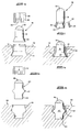
- the working face 10 of a drill crown contains a recess 12 which has been undercut to form a flared, in this case conically shaped portion 14 of expanded cross section.
- the recess 12 has a diameter of dimension d.
- a studcutter 16 has a post with a cylindrical portion 18, carrying an abrasive working end 20, and a conically shaped foot 22 at the other end. The diameter of the foot is no larger than the diameter d and is preferably slightly less.
- the studcutter 16 is located in the recess 12, foot first, so that the foot 22 locates in the flared portion 14 of the recess. It will be noted that the relative dimensions of the recess and of the studcutter post are such that a vacant space is left between the studcutter post 18 and the walls 26 of the recess.
- a deformable sleeve 24 is positioned around the studcutter and is forced axially into the recess 12. With the application of sufficient force, the lower portion of the sleeve 24 is caused to expand around the foot 20 of the studcutter.
- force is applied to the sleeve by means of a tubular punch which presses against the upper edge of the sleeve and drives the sleeve in a direction into the recess 12.
- the sleeve material will typically be a relatively pliable material such as mild or stainless steel or a plastics material, so that it can be made to deform in a manner to conform to the shape of the space existing between the wall of the recess and the studcutter post.
- the studcutter assembly is shown in assembled form in the working face of the drill bit in Figure 1b.
- the lower portion of the sleeve 24 has expanded to surround the foot 22 of the studcutter 16 and occupy the undercut, flared portion 14 of the recess 12.
- the sleeve 24 serves to lock the studcutter in the working face 10 with its working end 20 exposed and standing proud of the working face. Any force exerted applied to the studcutter in a direction to pull it from the drill crown will result merely in forces, indicated by the arrows in Figure 1b, being applied to the wall of the recess.
- the wall 26 exerts opposing forces on the studcutter and sleeve, thereby locking them in position in the recess.
- the studcutter secural method illustrated by Figures 1a and 1b was tested in the laboratory for impact and torque resistance.
- the test for impact resistance was performed using a standard Izod impact tester made by Avery.
- a pendulum-suspended impactor chisel was swung transversely so as to impact against the upstanding portion of the studcutter post.
- the studcutter post was machined to have a flat surface against which the corresponding flat surface of the impactor chisel could strike fully.
- the pendulum was given 300J of kinetic energy for each blow against the cutter post.
- Torque resistance tests were performed using a torque wrench with a suitable adaptor to engage the studcutter post, and measurements were made of the torque required to rotate the post in its mounting.
- FIG. 2 A second embodiment of the invention is shown in Figure 2.
- the studcutter 16 has a post 18 with an end section 22 and a reduced diameter neck section 32.
- the illustrated shape is achieved by appropriate machining of the cylindrical post of a conventional bullet-shaped studcutter.
- Collets 34 are secured to the post 18 in the region of the neck section and create a flared foot for the post as illustrated.
- the collets may be secured in the illustrated positions by means of a suitable adhesive.
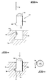
- FIG. 3a A third embodiment of the invention is illustrated in Figures 3a and 3b.
- the post of a studcutter 40 has a thickened waist portion 42 between its end 44 and the abrasive working end 46.
- the recess 48 in the working face 50 of a drill bit has a similar shape.
- the studcutter post is inserted into the recess 48 and an expandable sleeve 52, similar to the sleeve 24 of the first embodiment, is then forced into position around the post 40 and the thickened waist portion 42 to lock the studcutter post in the recess.
- FIG. 4a A fourth embodiment of the invention is illustrated by Figures 4a, 4b, and 4c.
- a studcutter 60 has a post 62 having an abrasive working end 64. Close to the opposite end 66 is a projection 68.
- a recess 70 formed in the working face 72 of a drill bit includes an enlargement or "bubble" 74 formed at its lower end.
- the bubble 74 is shaped to accommodate the projection 68 on the post 62.
- a groove 76 extends from the working face 72 to the bubble 74.
- the studcutter post 62 is inserted into the recess 70.
- the groove 76 acts as a keyway to guide the projection 68 into the bubble 74.
- a strip insert 78 is forced down the groove 76 and around the projection 68, as shown in Figure 4b, to lock the studcutter post in the recess.
- this embodiment can be expected to have a higher torsional resistance than the earlier embodiments.
- the exposed top surface of the sleeve or strip in the relevant embodiments can be provided with an abrasive protective layer.
- the abrasive working end of each cutting insert is preferably provided by a diamond compact.
Landscapes
- Engineering & Computer Science (AREA)
- Mechanical Engineering (AREA)
- Geology (AREA)
- Life Sciences & Earth Sciences (AREA)
- Mining & Mineral Resources (AREA)
- General Life Sciences & Earth Sciences (AREA)
- Fluid Mechanics (AREA)
- Environmental & Geological Engineering (AREA)
- Physics & Mathematics (AREA)
- Geochemistry & Mineralogy (AREA)
- Polishing Bodies And Polishing Tools (AREA)
- Processing Of Stones Or Stones Resemblance Materials (AREA)
- Drilling Tools (AREA)
- Ceramic Products (AREA)
- Soft Magnetic Materials (AREA)
- Earth Drilling (AREA)
Applications Claiming Priority (2)
| Application Number | Priority Date | Filing Date | Title |
|---|---|---|---|
| ZA923894 | 1992-05-27 | ||
| ZA923894 | 1992-05-27 |
Publications (2)
| Publication Number | Publication Date |
|---|---|
| EP0573135A1 true EP0573135A1 (de) | 1993-12-08 |
| EP0573135B1 EP0573135B1 (de) | 1998-05-27 |
Family
ID=66866004
Family Applications (1)
| Application Number | Title | Priority Date | Filing Date |
|---|---|---|---|
| EP93300808A Expired - Lifetime EP0573135B1 (de) | 1992-05-27 | 1993-02-04 | Abrasive Werkzeuge |
Country Status (10)
| Country | Link |
|---|---|
| US (1) | US5423719A (de) |
| EP (1) | EP0573135B1 (de) |
| JP (1) | JPH0633677A (de) |
| KR (1) | KR930023113A (de) |
| AT (1) | ATE166696T1 (de) |
| AU (1) | AU658045B2 (de) |
| CA (1) | CA2089122A1 (de) |
| DE (1) | DE69318760T2 (de) |
| NO (1) | NO930797L (de) |
| ZA (1) | ZA93584B (de) |
Cited By (9)
| Publication number | Priority date | Publication date | Assignee | Title |
|---|---|---|---|---|
| FR2725146A1 (fr) * | 1994-10-04 | 1996-04-05 | Bosch Gmbh Robert | Procede pour realiser une liaison sertie entre un insert et une piece tubulaire |
| WO2000034626A1 (en) * | 1998-12-08 | 2000-06-15 | Genesis Mining Technologies Limited | Cutting arrangement |
| WO2003012244A1 (de) | 2001-08-01 | 2003-02-13 | Techmo Entwicklungs- Und Vertriebs Gmbh | Bohrkrone |
| WO2010053710A2 (en) * | 2008-10-29 | 2010-05-14 | Baker Hughes Incorporated | Method and apparatus for robotic welding of drill bits |
| US8450637B2 (en) | 2008-10-23 | 2013-05-28 | Baker Hughes Incorporated | Apparatus for automated application of hardfacing material to drill bits |
| US8698038B2 (en) | 2008-09-18 | 2014-04-15 | Baker Hughes Incorporated | Method and apparatus for the automated application of hardfacing material to rolling cutters of earth-boring drill bits |
| WO2014102250A2 (en) * | 2012-12-31 | 2014-07-03 | Element Six Abrasives S.A. | A cutter element for rock removal applications |
| WO2014102248A3 (en) * | 2012-12-31 | 2015-04-09 | Element Six Abrasives S.A. | A cutter element for rock removal applications |
| US9439277B2 (en) | 2008-10-23 | 2016-09-06 | Baker Hughes Incorporated | Robotically applied hardfacing with pre-heat |
Families Citing this family (25)
| Publication number | Priority date | Publication date | Assignee | Title |
|---|---|---|---|---|
| GB9614961D0 (en) * | 1996-07-16 | 1996-09-04 | Perkin Elmer Ltd | Carrier and its use in the preparation of samples for spectroscopy |
| US5964653A (en) * | 1997-07-11 | 1999-10-12 | Applied Materials, Inc. | Carrier head with a flexible membrane for a chemical mechanical polishing system |
| JP2000176724A (ja) * | 1998-12-09 | 2000-06-27 | Mitsubishi Materials Corp | 嵌合式切削工具 |
| US20040072518A1 (en) * | 1999-04-02 | 2004-04-15 | Applied Materials, Inc. | Platen with patterned surface for chemical mechanical polishing |
| US20020137433A1 (en) * | 2001-03-26 | 2002-09-26 | Lee Lawrence K. | Abrasive drill bit |
| DE20116110U1 (de) * | 2001-10-01 | 2001-12-06 | Arminius-Schleifmittel GmbH, 32760 Detmold | Rotationsschleifwerkzeug |
| SE525501C2 (sv) | 2003-06-11 | 2005-03-01 | Htc Sweden Ab | Slipplatta samt en slipelementbärande hållarplatta för lösbar montering på en slipplatta |
| AU2007201463B2 (en) * | 2003-08-13 | 2010-09-09 | Sandvik Intellectual Property Ab | Shaped inserts with increased retention force |
| US7416035B2 (en) * | 2003-08-13 | 2008-08-26 | Smith International, Inc. | Shaped inserts with increased retention force |
| US20070110924A1 (en) * | 2005-11-14 | 2007-05-17 | Yelon William B | Process for improving the color of gemstones and gemstone minerals obtained thereby |
| DK2271452T3 (da) * | 2008-03-18 | 2012-12-03 | Franz-Josef Pokolm | Fræseværktøj til spåntagende bearbejdning af arbejdsstykker |
| JP4856689B2 (ja) * | 2008-11-10 | 2012-01-18 | 株式会社丸和技研 | 掘削ビット |
| DE102011104854B4 (de) * | 2011-06-21 | 2015-06-11 | Khd Humboldt Wedag Gmbh | Mahlwalze mit in die Oberfläche eingesetzten Hartkörpern |
| EP2586960B1 (de) * | 2011-10-27 | 2016-01-13 | Sandvik Intellectual Property AB | Bohrspitze mit einem absenkknopf und gesteinsbohrwerkzeug zur verwendung mit einer solchen bohrspitze |
| JP6127463B2 (ja) | 2011-11-30 | 2017-05-17 | 三菱マテリアル株式会社 | 掘削工具 |
| WO2013085869A1 (en) | 2011-12-05 | 2013-06-13 | Smith International Inc. | Rotating cutting elements for pdc bits |
| WO2013101860A1 (en) * | 2011-12-29 | 2013-07-04 | Smith International Inc. | Split sleeves for rolling cutters |
| US9140071B2 (en) | 2012-11-26 | 2015-09-22 | National Oilwell DHT, L.P. | Apparatus and method for retaining inserts of a rolling cone drill bit |
| WO2016114344A1 (ja) * | 2015-01-14 | 2016-07-21 | 三菱マテリアル株式会社 | 掘削チップおよび掘削ビット |
| JP6701742B2 (ja) | 2015-01-14 | 2020-05-27 | 三菱マテリアル株式会社 | 掘削チップおよび掘削ビット |
| WO2017218000A1 (en) * | 2016-06-17 | 2017-12-21 | Halliburton Energy Services, Inc. | Rolling element with half lock |
| JP1569597S (de) * | 2016-07-14 | 2017-02-20 | ||
| JP1569599S (de) * | 2016-07-14 | 2017-02-20 | ||
| JP1569589S (de) * | 2016-07-14 | 2017-02-20 | ||
| USD926545S1 (en) * | 2019-08-16 | 2021-08-03 | Ali Industries, Llc | Hex driver stripper sander |
Citations (13)
| Publication number | Priority date | Publication date | Assignee | Title |
|---|---|---|---|---|
| GB448821A (en) * | 1934-10-09 | 1936-06-16 | Wallramit Handel Mij Nv | Improvements in percussive rock drills |
| US2575438A (en) * | 1949-09-28 | 1951-11-20 | Kennametal Inc | Percussion drill bit body |
| US2628821A (en) * | 1950-10-07 | 1953-02-17 | Kennametal Inc | Percussion drill bit body |
| GB707021A (en) * | 1951-03-01 | 1954-04-07 | Skf Svenska Kullagerfab Ab | Improvements relating to rock drills |
| US3006424A (en) * | 1958-05-23 | 1961-10-31 | Sandvikens Jernverks Ab | Rock drill bits and cutting inserts therefor |
| US3540537A (en) * | 1969-06-02 | 1970-11-17 | Longyear Co E J | Slotted core lifter apparatus |
| US3749190A (en) * | 1971-05-06 | 1973-07-31 | Ingersoll Rand Co | Retaining carbide in rock drill bits |
| US3805364A (en) * | 1969-09-04 | 1974-04-23 | Mission Mfg Co | Method of mounting cutter inserts in bit bodies and removing the same therefrom |
| US4271917A (en) * | 1979-04-09 | 1981-06-09 | Syndrill Products Joint Venture | Locking device for hard metal inserts |
| EP0032428A1 (de) * | 1980-01-10 | 1981-07-22 | Stonehouse U.K. Limited | Drehbohrmeissel |
| US4445580A (en) * | 1979-06-19 | 1984-05-01 | Syndrill Carbide Diamond Company | Deep hole rock drill bit |
| DE3637456A1 (de) * | 1986-06-09 | 1988-05-11 | Erich Wezel | Hohlbohrkrone |
| FR2609750A1 (fr) * | 1987-01-19 | 1988-07-22 | Vennin Henri | Trepan de forage monobloc rotatif |
Family Cites Families (6)
| Publication number | Priority date | Publication date | Assignee | Title |
|---|---|---|---|---|
| DE558200C (de) * | 1929-04-20 | 1932-09-02 | Max Tamaschke | Ringfoermiger Schleiferstein zur Gewinnung von Holzschliff |
| US2724222A (en) * | 1953-08-04 | 1955-11-22 | Norton Co | Pulpstone |
| US2937433A (en) * | 1957-02-15 | 1960-05-24 | Walter G See | Inserted-blade milling cutters |
| US2972287A (en) * | 1957-04-24 | 1961-02-21 | Walter G See | Milling of metals subject to galling |
| NL7703234A (nl) * | 1977-03-25 | 1978-09-27 | Skf Ind Trading & Dev | Werkwijze voor het vervaardigen van een boorkop voorzien van harde slijtvaste elementen, als- mede boorkop vervaardigd volgens de werkwijze. |
| US4199035A (en) * | 1978-04-24 | 1980-04-22 | General Electric Company | Cutting and drilling apparatus with threadably attached compacts |
-
1993
- 1993-01-27 ZA ZA93584A patent/ZA93584B/xx unknown
- 1993-02-04 EP EP93300808A patent/EP0573135B1/de not_active Expired - Lifetime
- 1993-02-04 AT AT93300808T patent/ATE166696T1/de not_active IP Right Cessation
- 1993-02-04 DE DE69318760T patent/DE69318760T2/de not_active Expired - Fee Related
- 1993-02-09 CA CA002089122A patent/CA2089122A1/en not_active Abandoned
- 1993-02-10 AU AU32927/93A patent/AU658045B2/en not_active Ceased
- 1993-02-11 US US08/016,775 patent/US5423719A/en not_active Expired - Fee Related
- 1993-02-18 KR KR1019930002230A patent/KR930023113A/ko not_active Application Discontinuation
- 1993-03-04 NO NO930797A patent/NO930797L/no unknown
- 1993-03-23 JP JP5064069A patent/JPH0633677A/ja active Pending
Patent Citations (13)
| Publication number | Priority date | Publication date | Assignee | Title |
|---|---|---|---|---|
| GB448821A (en) * | 1934-10-09 | 1936-06-16 | Wallramit Handel Mij Nv | Improvements in percussive rock drills |
| US2575438A (en) * | 1949-09-28 | 1951-11-20 | Kennametal Inc | Percussion drill bit body |
| US2628821A (en) * | 1950-10-07 | 1953-02-17 | Kennametal Inc | Percussion drill bit body |
| GB707021A (en) * | 1951-03-01 | 1954-04-07 | Skf Svenska Kullagerfab Ab | Improvements relating to rock drills |
| US3006424A (en) * | 1958-05-23 | 1961-10-31 | Sandvikens Jernverks Ab | Rock drill bits and cutting inserts therefor |
| US3540537A (en) * | 1969-06-02 | 1970-11-17 | Longyear Co E J | Slotted core lifter apparatus |
| US3805364A (en) * | 1969-09-04 | 1974-04-23 | Mission Mfg Co | Method of mounting cutter inserts in bit bodies and removing the same therefrom |
| US3749190A (en) * | 1971-05-06 | 1973-07-31 | Ingersoll Rand Co | Retaining carbide in rock drill bits |
| US4271917A (en) * | 1979-04-09 | 1981-06-09 | Syndrill Products Joint Venture | Locking device for hard metal inserts |
| US4445580A (en) * | 1979-06-19 | 1984-05-01 | Syndrill Carbide Diamond Company | Deep hole rock drill bit |
| EP0032428A1 (de) * | 1980-01-10 | 1981-07-22 | Stonehouse U.K. Limited | Drehbohrmeissel |
| DE3637456A1 (de) * | 1986-06-09 | 1988-05-11 | Erich Wezel | Hohlbohrkrone |
| FR2609750A1 (fr) * | 1987-01-19 | 1988-07-22 | Vennin Henri | Trepan de forage monobloc rotatif |
Cited By (21)
| Publication number | Priority date | Publication date | Assignee | Title |
|---|---|---|---|---|
| FR2725146A1 (fr) * | 1994-10-04 | 1996-04-05 | Bosch Gmbh Robert | Procede pour realiser une liaison sertie entre un insert et une piece tubulaire |
| WO2000034626A1 (en) * | 1998-12-08 | 2000-06-15 | Genesis Mining Technologies Limited | Cutting arrangement |
| GB2369137A (en) * | 1998-12-08 | 2002-05-22 | Genesis Mining Technologies | Cutting arrangement |
| AU759672B2 (en) * | 1998-12-08 | 2003-04-17 | Genesis Mining Technologies (Pty) Limited | Cutting arrangement |
| US6712431B1 (en) | 1998-12-08 | 2004-03-30 | Genesis Mining Technologies (Pty) Limited | Cutting arrangement |
| GB2369137B (en) * | 1998-12-08 | 2004-05-26 | Genesis Mining Technologies | Cutting arrangement |
| WO2003012244A1 (de) | 2001-08-01 | 2003-02-13 | Techmo Entwicklungs- Und Vertriebs Gmbh | Bohrkrone |
| US6926104B2 (en) | 2001-08-01 | 2005-08-09 | Techmo Entwicklungs- Und Vertriebs Gmbh | Drill crown |
| US8698038B2 (en) | 2008-09-18 | 2014-04-15 | Baker Hughes Incorporated | Method and apparatus for the automated application of hardfacing material to rolling cutters of earth-boring drill bits |
| US8450637B2 (en) | 2008-10-23 | 2013-05-28 | Baker Hughes Incorporated | Apparatus for automated application of hardfacing material to drill bits |
| US8969754B2 (en) | 2008-10-23 | 2015-03-03 | Baker Hughes Incorporated | Methods for automated application of hardfacing material to drill bits |
| US9439277B2 (en) | 2008-10-23 | 2016-09-06 | Baker Hughes Incorporated | Robotically applied hardfacing with pre-heat |
| US9580788B2 (en) | 2008-10-23 | 2017-02-28 | Baker Hughes Incorporated | Methods for automated deposition of hardfacing material on earth-boring tools and related systems |
| WO2010053710A3 (en) * | 2008-10-29 | 2010-07-08 | Baker Hughes Incorporated | Method and apparatus for robotic welding of drill bits |
| WO2010053710A2 (en) * | 2008-10-29 | 2010-05-14 | Baker Hughes Incorporated | Method and apparatus for robotic welding of drill bits |
| US8948917B2 (en) | 2008-10-29 | 2015-02-03 | Baker Hughes Incorporated | Systems and methods for robotic welding of drill bits |
| WO2014102250A2 (en) * | 2012-12-31 | 2014-07-03 | Element Six Abrasives S.A. | A cutter element for rock removal applications |
| WO2014102248A3 (en) * | 2012-12-31 | 2015-04-09 | Element Six Abrasives S.A. | A cutter element for rock removal applications |
| WO2014102250A3 (en) * | 2012-12-31 | 2015-04-09 | Element Six Abrasives S.A. | A cutter element for rock removal applications |
| US10036208B2 (en) | 2012-12-31 | 2018-07-31 | Element Six Abrasives S.A. | Cutter element for rock removal applications |
| US10180034B2 (en) | 2012-12-31 | 2019-01-15 | Element Six Abrasives S.A. | Cutter element for rock removal applications |
Also Published As
| Publication number | Publication date |
|---|---|
| CA2089122A1 (en) | 1993-11-28 |
| ATE166696T1 (de) | 1998-06-15 |
| ZA93584B (en) | 1993-09-01 |
| DE69318760D1 (de) | 1998-07-02 |
| US5423719A (en) | 1995-06-13 |
| KR930023113A (ko) | 1993-12-18 |
| DE69318760T2 (de) | 1999-01-28 |
| AU658045B2 (en) | 1995-03-30 |
| NO930797D0 (no) | 1993-03-04 |
| JPH0633677A (ja) | 1994-02-08 |
| NO930797L (no) | 1993-11-29 |
| AU3292793A (en) | 1993-12-02 |
| EP0573135B1 (de) | 1998-05-27 |
Similar Documents
| Publication | Publication Date | Title |
|---|---|---|
| US5423719A (en) | Abrasive tools | |
| US6450272B2 (en) | Rock drill | |
| US5150636A (en) | Rock drill bit and method of making same | |
| US4625593A (en) | Wood drill and method of construction | |
| US4289211A (en) | Rock drill bit | |
| EP0236086B1 (de) | Einsatz für ein Werkzeug | |
| US4889200A (en) | Rock drill | |
| US3970158A (en) | Tooth loading for earth boring bits | |
| EP0104893A2 (de) | Werkzeugeinsatz | |
| US6116827A (en) | Drilling tool | |
| US3918538A (en) | Rotary percussion earth boring bit | |
| JPH02212612A (ja) | 固定素子 | |
| EP1200232B1 (de) | Aufsatz für ein schlagwerkzeugarbeitsgerät | |
| CA2398694A1 (en) | Device for connecting two tool parts | |
| US5836405A (en) | Fastening apparatus for and method of setting fastening elements | |
| US5456329A (en) | Bifurcated drill bit construction | |
| US5458211A (en) | Spade drill bit construction | |
| PT790387E (pt) | Broca perfuradora para rocha bem como processo para o seu fabrico | |
| US4817741A (en) | Rotary drill | |
| GB2084219A (en) | Mounting of cutters on cutting tools | |
| CA1037253A (en) | Impact or demolition tool | |
| US4258808A (en) | Rock drill | |
| WO2000006329A3 (en) | Short-hole drill bit | |
| JPS6015108A (ja) | コンクリートにあけられた孔の拡径方法とその装置 | |
| US6516904B1 (en) | Mining drill steels and methods of making the same |
Legal Events
| Date | Code | Title | Description |
|---|---|---|---|
| PUAI | Public reference made under article 153(3) epc to a published international application that has entered the european phase |
Free format text: ORIGINAL CODE: 0009012 |
|
| AK | Designated contracting states |
Kind code of ref document: A1 Designated state(s): AT BE CH DE ES FR GB IE IT LI NL SE |
|
| 17P | Request for examination filed |
Effective date: 19940511 |
|
| 17Q | First examination report despatched |
Effective date: 19960117 |
|
| GRAG | Despatch of communication of intention to grant |
Free format text: ORIGINAL CODE: EPIDOS AGRA |
|
| RAP1 | Party data changed (applicant data changed or rights of an application transferred) |
Owner name: DE BEERS INDUSTRIAL DIAMOND DIVISION (PROPRIETARY) |
|
| GRAG | Despatch of communication of intention to grant |
Free format text: ORIGINAL CODE: EPIDOS AGRA |
|
| GRAH | Despatch of communication of intention to grant a patent |
Free format text: ORIGINAL CODE: EPIDOS IGRA |
|
| GRAH | Despatch of communication of intention to grant a patent |
Free format text: ORIGINAL CODE: EPIDOS IGRA |
|
| GRAA | (expected) grant |
Free format text: ORIGINAL CODE: 0009210 |
|
| AK | Designated contracting states |
Kind code of ref document: B1 Designated state(s): AT BE CH DE ES FR GB IE IT LI NL SE |
|
| PG25 | Lapsed in a contracting state [announced via postgrant information from national office to epo] |
Ref country code: NL Free format text: LAPSE BECAUSE OF FAILURE TO SUBMIT A TRANSLATION OF THE DESCRIPTION OR TO PAY THE FEE WITHIN THE PRESCRIBED TIME-LIMIT Effective date: 19980527 Ref country code: LI Free format text: LAPSE BECAUSE OF FAILURE TO SUBMIT A TRANSLATION OF THE DESCRIPTION OR TO PAY THE FEE WITHIN THE PRESCRIBED TIME-LIMIT Effective date: 19980527 Ref country code: IT Free format text: LAPSE BECAUSE OF FAILURE TO SUBMIT A TRANSLATION OF THE DESCRIPTION OR TO PAY THE FEE WITHIN THE PRE;WARNING: LAPSES OF ITALIAN PATENTS WITH EFFECTIVE DATE BEFORE 2007 MAY HAVE OCCURRED AT ANY TIME BEFORE 2007. THE CORRECT EFFECTIVE DATE MAY BE DIFFERENT FROM THE ONE RECORDED.SCRIBED TIME-LIMIT Effective date: 19980527 Ref country code: ES Free format text: THE PATENT HAS BEEN ANNULLED BY A DECISION OF A NATIONAL AUTHORITY Effective date: 19980527 Ref country code: CH Free format text: LAPSE BECAUSE OF FAILURE TO SUBMIT A TRANSLATION OF THE DESCRIPTION OR TO PAY THE FEE WITHIN THE PRESCRIBED TIME-LIMIT Effective date: 19980527 Ref country code: BE Free format text: LAPSE BECAUSE OF FAILURE TO SUBMIT A TRANSLATION OF THE DESCRIPTION OR TO PAY THE FEE WITHIN THE PRESCRIBED TIME-LIMIT Effective date: 19980527 Ref country code: AT Free format text: LAPSE BECAUSE OF FAILURE TO SUBMIT A TRANSLATION OF THE DESCRIPTION OR TO PAY THE FEE WITHIN THE PRESCRIBED TIME-LIMIT Effective date: 19980527 |
|
| REF | Corresponds to: |
Ref document number: 166696 Country of ref document: AT Date of ref document: 19980615 Kind code of ref document: T |
|
| REG | Reference to a national code |
Ref country code: CH Ref legal event code: EP |
|
| REF | Corresponds to: |
Ref document number: 69318760 Country of ref document: DE Date of ref document: 19980702 |
|
| REG | Reference to a national code |
Ref country code: IE Ref legal event code: FG4D |
|
| ET | Fr: translation filed | ||
| NLV1 | Nl: lapsed or annulled due to failure to fulfill the requirements of art. 29p and 29m of the patents act | ||
| REG | Reference to a national code |
Ref country code: CH Ref legal event code: PL |
|
| PG25 | Lapsed in a contracting state [announced via postgrant information from national office to epo] |
Ref country code: IE Free format text: LAPSE BECAUSE OF NON-PAYMENT OF DUE FEES Effective date: 19990204 |
|
| PGFP | Annual fee paid to national office [announced via postgrant information from national office to epo] |
Ref country code: SE Payment date: 19990204 Year of fee payment: 7 Ref country code: GB Payment date: 19990204 Year of fee payment: 7 |
|
| PGFP | Annual fee paid to national office [announced via postgrant information from national office to epo] |
Ref country code: FR Payment date: 19990209 Year of fee payment: 7 |
|
| PGFP | Annual fee paid to national office [announced via postgrant information from national office to epo] |
Ref country code: DE Payment date: 19990212 Year of fee payment: 7 |
|
| PLBE | No opposition filed within time limit |
Free format text: ORIGINAL CODE: 0009261 |
|
| STAA | Information on the status of an ep patent application or granted ep patent |
Free format text: STATUS: NO OPPOSITION FILED WITHIN TIME LIMIT |
|
| 26N | No opposition filed | ||
| REG | Reference to a national code |
Ref country code: IE Ref legal event code: MM4A |
|
| PG25 | Lapsed in a contracting state [announced via postgrant information from national office to epo] |
Ref country code: GB Free format text: LAPSE BECAUSE OF NON-PAYMENT OF DUE FEES Effective date: 20000204 |
|
| PG25 | Lapsed in a contracting state [announced via postgrant information from national office to epo] |
Ref country code: SE Free format text: LAPSE BECAUSE OF NON-PAYMENT OF DUE FEES Effective date: 20000205 |
|
| GBPC | Gb: european patent ceased through non-payment of renewal fee |
Effective date: 20000204 |
|
| EUG | Se: european patent has lapsed |
Ref document number: 93300808.8 |
|
| PG25 | Lapsed in a contracting state [announced via postgrant information from national office to epo] |
Ref country code: FR Free format text: LAPSE BECAUSE OF NON-PAYMENT OF DUE FEES Effective date: 20001031 |
|
| PG25 | Lapsed in a contracting state [announced via postgrant information from national office to epo] |
Ref country code: DE Free format text: LAPSE BECAUSE OF NON-PAYMENT OF DUE FEES Effective date: 20001201 |
|
| REG | Reference to a national code |
Ref country code: FR Ref legal event code: ST |