EP1200232B1 - Aufsatz für ein schlagwerkzeugarbeitsgerät - Google Patents
Aufsatz für ein schlagwerkzeugarbeitsgerät Download PDFInfo
- Publication number
- EP1200232B1 EP1200232B1 EP00949782A EP00949782A EP1200232B1 EP 1200232 B1 EP1200232 B1 EP 1200232B1 EP 00949782 A EP00949782 A EP 00949782A EP 00949782 A EP00949782 A EP 00949782A EP 1200232 B1 EP1200232 B1 EP 1200232B1
- Authority
- EP
- European Patent Office
- Prior art keywords
- attachment
- hole
- wall
- percussive tool
- percussive
- Prior art date
- Legal status (The legal status is an assumption and is not a legal conclusion. Google has not performed a legal analysis and makes no representation as to the accuracy of the status listed.)
- Expired - Lifetime
Links
Images


Classifications
-
- B—PERFORMING OPERATIONS; TRANSPORTING
- B25—HAND TOOLS; PORTABLE POWER-DRIVEN TOOLS; MANIPULATORS
- B25D—PERCUSSIVE TOOLS
- B25D17/00—Details of, or accessories for, portable power-driven percussive tools
- B25D17/02—Percussive tool bits
Definitions
- WO79/00771 discloses a scabbler bit having pointed tips separated by chisel shaped cutting tips, arranged in rows. The bit is attached to a percussive tool and is used for roughening, abrading or removing projections from hard surfaces.
- an attachment for a percussive tool comprises:
- a method for forming a hole in a wall comprises the steps of:
- the parallel planar blades create a series of parallel grooves in the wall and the attachment is then rotated through an angle and applied again to break up the ridges between the grooves to remove an area of wall in the shape of the attachment.
- the attachment For an attachment shape having N-fold rotational symmetry, the attachment must be rotated through approximately 360°/N, or a multiple thereof, such that the outline of the second cut overlays the first, but the grooves formed by the blades cross those formed by the first cut.
- the debris is ejected through the spaces between the chisel blades.
- Means may be provided to limit the depth to which the hole is chiseled, for instance a projection may be provided on the edge of the attachment. This allows a hole of a predetermined depth to be produced. Slots may be provided in the back of the device between the chisel blades to allow debris to more easily be ejected.
- the saw tooth shaped projections along each blade improve the cutting ability of the attachment and also allow the debris produced to more easily be ejected from under the attachment. They reduce the contact area of the attachment on the wall, compared to the contact area of blades having continuous edges, which allows the attachment to be used with more lightweight, less powerful tools.
- the spacing of the blades and the pitch of the teeth may be chosen to match the power of the tool.
- the attachment of the present invention may be designed to produce holes of a variety of shapes having. rotational symmetry.
- the parallel chisel blades may vary in length such that the whole tool has a circular formation. Rotating such an attachment through any angle less than 180° for the second cut would result in a circular hole.
- the tool For producing a hole in the shape of an equilateral triangle, the tool must have an equilateral triangular shape and the rotation must be through 120° such that the second cut overlays the first cut.
- the chisel blades are arranged to form a square and the attachment is rotated through 90° to form a square hole.
- the attachment comprises an attachment head and a drive impact shaft.
- the means for connecting the attachment to a percussive tool comprises a standard fitting such as an SDS fitting, an SDS Max fitting, or similar chucks used on percussive power tools, or other means to connect to the percussive tool. Therefore, by providing drive impact shafts having a variety of standard fittings, the attachment may be fitted to the chuck of almost any percussive tool such as a so called combie drill or impact breaker.
- the drive impact shaft is connected to the attachment head by means of a taper fit.
- locking means are provided to lock the taper fit in engagement.
- a number 2 Morse taper angles are preferably used and the head of the tool is retained by a centralizing and locking screw.
- the shaft may be released by removing the locking screw and using a parallel punch of a smaller diameter than the screw thread against the base of the screwed hole in the shaft.
- the attachment head may be readily replaced when it is worn by detaching it from the drive impact shaft.
- the attachment is formed from hard cast metal formed by an investment casting operation. It is therefore straightforward to manufacture and replace when worn.
- the attachment also includes a locating rod protruding from the centre of the attachment head beyond the extent of the chisel blades.
- the locating rod screws into the end of the drive impact shaft and provides the means for locking the taper fit.
- the locating rod may be used to locate the device by locating the rod in a pre-drilled hole whilst forming the first set of parallel grooves to locate the attachment as it is rotated through 90°. This therefore ensures that the second cut overlays the first and the hole is the correct shape.
- the rod also may serve to limit the depth of the hole chiseled when it reaches the bottom of the pre-drilled hole.
- the pre-drilled hole is drilled using a standard electric drill and is there to be used as a hole for a plastic wall plug for a fixing screw for fixing the box to the wall.
- a hole which is not square but rectangular, for instance a hole for a double power point.
- This can readily be achieved with the device of the present invention by forming a second square hole adjacent to or partly overlapping the first. Means may be provided to aid in location of the second square hole such as a template which fits into the first square hole and carries a guide for locating the pre-drilled hole for locating the second square hole.
- double wall boxes are of the same height as the single wall boxes and therefore the same attachment may be used to form rectangular holes for double wall boxes.
- the present invention is particularly suited for use in an electric hand tool capable of percussive action such as a Combie drill or impact breaker. However, it may also be used with a pneumatic percussive tool.
- FIGS 1, 2, 5 and 6 show an attachment according to an embodiment of the invention.
- the attachment head 1 is attached to a drive impact shaft by means of a taper 3;4.
- a flange 7 engages the edge of the hole in the attachment head 1 and the taper 3,4 is locked in engagement.
- the attachment head 1 can therefore readily be removed from the drive impact shaft 2 by unscrewing the locating rod 5. This allows easy replacement of the attachment head 1 when it becomes worn, or if a different size head is required.
- the locating rod 5 includes a hole 8 at its end for inserting a rod or key for easy unscrewing of the locating rod 5 from the drive impact shaft 2.
- the drive impact shaft 2 is attached to a portable electric combie drill or impact breaker by means of a standard SDS Max attachment.
- the same attachment head 1 may be fitted to a drive impact shaft having a different fitting for attachment to a drill having a different type of fitting such as a three jaw chuck.
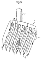
- the attachment head 1 comprises seven parallel chisel blades 9.
- the chisel blades are spaced at approximately 13 mm, such that the width of the attachment is 80 mm. This is the standard size of a wall box for a light switch or power point.
- the locating rod 5 protrudes beyond the extent of the chisel blades 9.
- FIG 2 shows the attachment of Figure 1 rotated through 90°.
- Each chisel blade 9 has a plurality of saw tooth shaped projections 10 along its cutting edge. This improves the cutting ability of the attachment and also allows the debris to be expelled easily from under the blades 9 when the attachment is in use.
- the length of the attachment is also 80 mm.
- the attachment includes slots 14 formed in its back between the chisel blades 9 for allowing debris to be expelled.
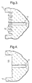
- Figures 3 and 4 illustrate the how the attachment is used to form a square hole 15 for receiving a wall box for a power point or light switch.
- a hole 11 is drilled using a standard drill. The hole 11 is used to receive the locating rod 5. As the locating rod 5 enters the hole 11, the chisel blades 9 come into contact with the wall 12, cutting parallel grooves 13, as shown in Figure 3.
- the depth of the hole formed in the wall may be determined either by when the locating rod 5 reaches the bottom of the hole 11, or by the depth of the attachment itself.
- the drill and attachment are then rotated through 90°, and, locating the rod 5 in the hole 11, a second cut is made.
- the ridges between the parallel grooves 13 crumble under the chisel blades 9 and the debris falls out through the gaps between the chisel blades 9.
- the necessary spacing of the chisel blades 9 is dependent on the material in which the hole is to be chiseled. If the spacing is too great, the second cut will result in a criss cross pattern of cuts rather than cause the ridges between the parallel grooves 13 to crumble. Material such as plaster which crumbles easily will not require as closely spaced chisel blades 9 as a harder material such as concrete. If the material is very soft a single cut may be sufficient to create a hole and the second cut may not be required.
- the present inventors have found that a spacing of between 10 mm and 13 mm is suitable for most materials.
Landscapes
- Engineering & Computer Science (AREA)
- Mechanical Engineering (AREA)
- Percussive Tools And Related Accessories (AREA)
- Processing Of Stones Or Stones Resemblance Materials (AREA)
- Turning (AREA)
- Shovels (AREA)
- Working Measures On Existing Buildindgs (AREA)
Claims (10)
- Aufsatz für ein Schlagwerkzeugarbeitsgerät, umfassend Mittel zum Verbinden des Aufsatzes mit einem Schlagwerkzeugarbeitsgerät und mehreren Reihen von Zähnen (10), die im wesentlichen parallel zueinander und voneinander beabstandet angeordnet sind, um eine Form auszubilden, die im wesentlichen rotationssymmetrisch ist um eine zentrale Achse, dadurch gekennzeichnet, daß jede Reihe von Zähnen (10) entlang der Kante einer planaren Meißelklinge (9) ausgebildet ist.
- Aufsatz für ein Schlagwerkzeugarbeitsgerät nach Anspruch 1, bei welchem die parallelen Reihen von Zähnen (10) derart angeordnet sind, daß sie ein Quadrat bilden.
- Aufsatz für ein Schlagwerkzeugarbeitsgerät nach Anspruch 1 oder 2, beinhaltend eine Führungsstange (5), die von dem Aufsatz entlang der zentralen Achse über die Erstrekkung der Zähne (10) hinausragt.
- Aufsatz für ein Schlagwerkzeugarbeitsgerät nach einem der vorstehenden Ansprüche, bei welchem der Aufsatz einen Aufsatzkopf (1) und einen Antriebsschlagschaft (2) umfaßt.
- Aufsatz für ein Schlagwerkzeugarbeitsgerät nach Anspruch 4, bei welchem der Aufsatzkopf (1) mit dem Antriebsschlagschaft (2) mit Hilfe einer Kegelpassung (3, 4) verbunden ist.
- Aufsatz für ein Schlagwerkzeugarbeitsgerät nach Anspruch 5, bei welchem Verriegelungsmittel zum Halten der Kegelpassung (3, 4) in Eingriff, vorgesehen sind.
- Aufsatz für ein Schlagwerkzeugarbeitsgerät nach Anspruch 6, bei welchem das Verriegelungsmittel zum Halten der Kegelpassung (3, 4) in Eingriff, die Führungsstange (5) umfaßt, die sich in das Ende des Antriebsschlagschaftes (2) schraubt.
- Verfahren zum Ausbilden eines Lochs in einer Wand, das die Schritte umfaßt:Vorsehen eines Aufsatzes für ein Schlagwerkzeugarbeitsgerät, der mehrere Reihen von Zähnen (10) hat, die im wesentlichen parallel zueinander und voneinander beabstandet angeordnet sind, um eine Form auszubilden, die im wesentlichen rotationssymmetrisch ist um eine zentrale Achse;Anbringen des Aufsatzes an einem Schlagwerkzeugarbeitsgerät;Anordnen des Aufsatzes in Kontakt mit der Wand und Bewirken eines Schlagbetriebs des Aufsatzes, dadurch gekennzeichnet, daß die Reihen von Zähnen (10) mehrere parallele Ausnehmungen (13) und Rippen in der Wand ausbilden und daß das Verfahren des weiteren den Schritt beinhaltet:Drehen des Aufsatzes um einen Winkel um die zentrale Achse und Anordnen des Aufsatzes in Kontakt mit der Wand in einer Stellung, in der er über den mehreren parallelen Ausnehmungen (13) liegt und Vorsehen eines Schlagbetriebes des Aufsatzes, um die Rippen aufzubrechen und ein Loch von im wesentlichen gleichförmiger Tiefe auszubilden.
- Verfahren zum Ausbilden eines Lochs in einer Wand nach Anspruch 8, beinhaltend die Schritte, zunächst ein kreisförmiges Loch (11) in die Wand zu bohren; Vorsehen einer Führungsstange (5) an der zentralen Achse des Aufsatzes, die über die Erstreckung der Zähne (10) hinaus vorsteht; Anordnen der Stange (5) in dem kreisförmigen Loch (11), während der erste Satz paralleler Ausnehmungen (13) ausgebildet wird; Anordnen der Stange 85) in dem kreisförmigen Loch (11), um den Aufsatz bei seiner Drehung zu führen.
- Verfahren zum Ausbilden eines Lochs in einer Wand nach Anspruch 8 oder 9, bei welchem das Verfahren, teilweise das erste Loch überlappend, wiederholt wird, um ein größeres Loch auszubilden.
Applications Claiming Priority (3)
| Application Number | Priority Date | Filing Date | Title |
|---|---|---|---|
| GB9918188A GB2351465B (en) | 1999-08-02 | 1999-08-02 | An attachment for a percussive tool |
| GB9918188 | 1999-08-02 | ||
| PCT/GB2000/002989 WO2001008853A1 (en) | 1999-08-02 | 2000-08-01 | An attachment for a percussive tool |
Publications (2)
| Publication Number | Publication Date |
|---|---|
| EP1200232A1 EP1200232A1 (de) | 2002-05-02 |
| EP1200232B1 true EP1200232B1 (de) | 2003-04-16 |
Family
ID=10858427
Family Applications (1)
| Application Number | Title | Priority Date | Filing Date |
|---|---|---|---|
| EP00949782A Expired - Lifetime EP1200232B1 (de) | 1999-08-02 | 2000-08-01 | Aufsatz für ein schlagwerkzeugarbeitsgerät |
Country Status (10)
| Country | Link |
|---|---|
| US (1) | US6681756B1 (de) |
| EP (1) | EP1200232B1 (de) |
| JP (1) | JP2003505264A (de) |
| AT (1) | ATE237435T1 (de) |
| AU (1) | AU6305000A (de) |
| DE (1) | DE60002211T2 (de) |
| ES (1) | ES2198333T3 (de) |
| GB (1) | GB2351465B (de) |
| WO (1) | WO2001008853A1 (de) |
| ZA (1) | ZA200200554B (de) |
Families Citing this family (11)
| Publication number | Priority date | Publication date | Assignee | Title |
|---|---|---|---|---|
| GB0520911D0 (en) * | 2005-10-14 | 2005-11-23 | C4 Carbides Plc | Power tool attachments |
| US20080066326A1 (en) * | 2006-09-15 | 2008-03-20 | Reed Jeff A | Apparatus and Method for cutting electrical outlet holes on gypsum board |
| DE102010028302A1 (de) * | 2010-04-28 | 2011-12-01 | Hilti Aktiengesellschaft | Bohrwerkzeug |
| CN102476222B (zh) * | 2010-11-24 | 2014-12-10 | 南京德朔实业有限公司 | 用于振荡工具上的开孔器 |
| JP5657436B2 (ja) * | 2011-03-16 | 2015-01-21 | 株式会社マキタ | 作業工具 |
| US9358623B2 (en) * | 2013-05-16 | 2016-06-07 | William Larry Burks | Hole cutting system |
| CA2942092A1 (en) * | 2015-09-15 | 2017-03-15 | Keystone Retaining Wall Systems Llc | Block splitter assembly and method of producing wall blocks |
| US20170157687A1 (en) | 2015-12-03 | 2017-06-08 | Mark Turner | Hole saw |
| CN108995409A (zh) * | 2018-08-15 | 2018-12-14 | 陕西法士特齿轮有限责任公司 | 一种用于对齿的通用标锤 |
| US10414037B1 (en) * | 2018-09-25 | 2019-09-17 | Michael Heavrin | Hammer drill adapter for driving cleats onto sheet metal edges |
| CN113263568A (zh) * | 2020-02-14 | 2021-08-17 | 罗天珍 | 错位式多边形开孔方法及多边形开孔凿 |
Family Cites Families (6)
| Publication number | Priority date | Publication date | Assignee | Title |
|---|---|---|---|---|
| WO1979000771A1 (en) * | 1978-03-16 | 1979-10-04 | Joad Eng Ltd | Scabbler bits |
| US4730395A (en) * | 1985-04-22 | 1988-03-15 | Blessing Sr William R | Apparatus for cutting holes for electrical wall outlets in wall covering panels |
| US4848309A (en) * | 1988-07-25 | 1989-07-18 | Johnny Alderete | Masonry punch |
| FR2655587A1 (fr) * | 1989-12-11 | 1991-06-14 | Koehl Jean Marie | Tete d'outil a percussion tel que beche, burin, etc... avec gorge d'evacuation des poussieres. |
| US5797189A (en) * | 1997-03-24 | 1998-08-25 | Carl L. Blalack | Tool for cutting rectilinear openings for electrical outlet boxes in sheet material |
| GB9903616D0 (en) * | 1999-02-18 | 1999-04-07 | Armeg Ltd | Square hole cutter |
-
1999
- 1999-08-02 GB GB9918188A patent/GB2351465B/en not_active Revoked
-
2000
- 2000-08-01 AU AU63050/00A patent/AU6305000A/en not_active Abandoned
- 2000-08-01 WO PCT/GB2000/002989 patent/WO2001008853A1/en not_active Ceased
- 2000-08-01 EP EP00949782A patent/EP1200232B1/de not_active Expired - Lifetime
- 2000-08-01 DE DE60002211T patent/DE60002211T2/de not_active Expired - Fee Related
- 2000-08-01 US US10/048,603 patent/US6681756B1/en not_active Expired - Fee Related
- 2000-08-01 ES ES00949782T patent/ES2198333T3/es not_active Expired - Lifetime
- 2000-08-01 JP JP2001513559A patent/JP2003505264A/ja active Pending
- 2000-08-01 AT AT00949782T patent/ATE237435T1/de not_active IP Right Cessation
-
2002
- 2002-01-22 ZA ZA200200554A patent/ZA200200554B/en unknown
Also Published As
| Publication number | Publication date |
|---|---|
| GB9918188D0 (en) | 1999-10-06 |
| JP2003505264A (ja) | 2003-02-12 |
| DE60002211D1 (de) | 2003-05-22 |
| WO2001008853A1 (en) | 2001-02-08 |
| GB2351465B (en) | 2003-02-19 |
| ZA200200554B (en) | 2003-03-26 |
| ES2198333T3 (es) | 2004-02-01 |
| AU6305000A (en) | 2001-02-19 |
| US6681756B1 (en) | 2004-01-27 |
| DE60002211T2 (de) | 2004-01-29 |
| EP1200232A1 (de) | 2002-05-02 |
| ATE237435T1 (de) | 2003-05-15 |
| GB2351465A (en) | 2001-01-03 |
Similar Documents
| Publication | Publication Date | Title |
|---|---|---|
| EP0454729B1 (de) | Grabwerkzeugzusammenbau mit doppelter möglichkeit zur einstellung in schritten | |
| GB2371506A (en) | Tool for producing a rebated hole | |
| EP1200232B1 (de) | Aufsatz für ein schlagwerkzeugarbeitsgerät | |
| USRE28900E (en) | Drill bit device | |
| US3687565A (en) | Drill bit device | |
| US3049358A (en) | Tooling and method of installing expansion shells | |
| WO2023215250A1 (en) | Recess tool for flush-mount trim | |
| US8100612B2 (en) | Core drill | |
| CA2387295A1 (en) | Multiple cutter rotary hammer bit | |
| WO2014155649A1 (ja) | 穿孔装置および穿孔方法 | |
| RU2183721C2 (ru) | Бур-расширитель | |
| WO2001030548A1 (en) | Cutter for forming polygonal holes | |
| AU2014227526B2 (en) | A tool | |
| IE20000054A1 (en) | Square hole cutter | |
| WO2010084551A1 (ja) | コアドリル | |
| JP2004001111A (ja) | 回転切削工具 | |
| GB2225262A (en) | Drill bit | |
| JP3214685U (ja) | ネジ回し用の凹部が破損しているネジの取外し具 | |
| EP0726989B1 (de) | Stecker | |
| RU17192U1 (ru) | Бур для перфоратора | |
| CN1418144A (zh) | 用于冲击工具的附件 | |
| JPH0241809A (ja) | 回転式孔あけ工具の面取り刃 | |
| JP2003042121A (ja) | 木ねじ | |
| JP2001088120A (ja) | 塑造構造物穿孔用ドリルおよび穿孔深さ設定用治具 | |
| EP3052737A1 (de) | Scherklauenbohrmeissel |
Legal Events
| Date | Code | Title | Description |
|---|---|---|---|
| PUAI | Public reference made under article 153(3) epc to a published international application that has entered the european phase |
Free format text: ORIGINAL CODE: 0009012 |
|
| 17P | Request for examination filed |
Effective date: 20020128 |
|
| AK | Designated contracting states |
Kind code of ref document: A1 Designated state(s): AT BE CH CY DE DK ES FI FR GB GR IE IT LI LU MC NL PT SE |
|
| AX | Request for extension of the european patent |
Free format text: AL;LT;LV;MK;RO;SI |
|
| 17Q | First examination report despatched |
Effective date: 20020515 |
|
| GRAH | Despatch of communication of intention to grant a patent |
Free format text: ORIGINAL CODE: EPIDOS IGRA |
|
| GRAH | Despatch of communication of intention to grant a patent |
Free format text: ORIGINAL CODE: EPIDOS IGRA |
|
| GRAA | (expected) grant |
Free format text: ORIGINAL CODE: 0009210 |
|
| AK | Designated contracting states |
Designated state(s): AT BE CH CY DE DK ES FI FR GB GR IE IT LI LU MC NL PT SE |
|
| PG25 | Lapsed in a contracting state [announced via postgrant information from national office to epo] |
Ref country code: LI Free format text: LAPSE BECAUSE OF FAILURE TO SUBMIT A TRANSLATION OF THE DESCRIPTION OR TO PAY THE FEE WITHIN THE PRESCRIBED TIME-LIMIT Effective date: 20030416 Ref country code: FI Free format text: LAPSE BECAUSE OF FAILURE TO SUBMIT A TRANSLATION OF THE DESCRIPTION OR TO PAY THE FEE WITHIN THE PRESCRIBED TIME-LIMIT Effective date: 20030416 Ref country code: CH Free format text: LAPSE BECAUSE OF FAILURE TO SUBMIT A TRANSLATION OF THE DESCRIPTION OR TO PAY THE FEE WITHIN THE PRESCRIBED TIME-LIMIT Effective date: 20030416 |
|
| REG | Reference to a national code |
Ref country code: GB Ref legal event code: FG4D |
|
| REG | Reference to a national code |
Ref country code: CH Ref legal event code: EP |
|
| REF | Corresponds to: |
Ref document number: 60002211 Country of ref document: DE Date of ref document: 20030522 Kind code of ref document: P |
|
| REG | Reference to a national code |
Ref country code: IE Ref legal event code: FG4D |
|
| PG25 | Lapsed in a contracting state [announced via postgrant information from national office to epo] |
Ref country code: SE Free format text: LAPSE BECAUSE OF FAILURE TO SUBMIT A TRANSLATION OF THE DESCRIPTION OR TO PAY THE FEE WITHIN THE PRESCRIBED TIME-LIMIT Effective date: 20030716 Ref country code: PT Free format text: LAPSE BECAUSE OF FAILURE TO SUBMIT A TRANSLATION OF THE DESCRIPTION OR TO PAY THE FEE WITHIN THE PRESCRIBED TIME-LIMIT Effective date: 20030716 Ref country code: GR Free format text: LAPSE BECAUSE OF FAILURE TO SUBMIT A TRANSLATION OF THE DESCRIPTION OR TO PAY THE FEE WITHIN THE PRESCRIBED TIME-LIMIT Effective date: 20030716 Ref country code: DK Free format text: LAPSE BECAUSE OF FAILURE TO SUBMIT A TRANSLATION OF THE DESCRIPTION OR TO PAY THE FEE WITHIN THE PRESCRIBED TIME-LIMIT Effective date: 20030716 |
|
| PG25 | Lapsed in a contracting state [announced via postgrant information from national office to epo] |
Ref country code: LU Free format text: LAPSE BECAUSE OF NON-PAYMENT OF DUE FEES Effective date: 20030801 Ref country code: IE Free format text: LAPSE BECAUSE OF NON-PAYMENT OF DUE FEES Effective date: 20030801 Ref country code: CY Free format text: LAPSE BECAUSE OF FAILURE TO SUBMIT A TRANSLATION OF THE DESCRIPTION OR TO PAY THE FEE WITHIN THE PRESCRIBED TIME-LIMIT Effective date: 20030801 Ref country code: AT Free format text: LAPSE BECAUSE OF NON-PAYMENT OF DUE FEES Effective date: 20030801 |
|
| PG25 | Lapsed in a contracting state [announced via postgrant information from national office to epo] |
Ref country code: MC Free format text: LAPSE BECAUSE OF NON-PAYMENT OF DUE FEES Effective date: 20030831 Ref country code: BE Free format text: LAPSE BECAUSE OF NON-PAYMENT OF DUE FEES Effective date: 20030831 |
|
| PGFP | Annual fee paid to national office [announced via postgrant information from national office to epo] |
Ref country code: FR Payment date: 20030909 Year of fee payment: 4 |
|
| PGFP | Annual fee paid to national office [announced via postgrant information from national office to epo] |
Ref country code: DE Payment date: 20030911 Year of fee payment: 4 |
|
| LTIE | Lt: invalidation of european patent or patent extension |
Effective date: 20030416 |
|
| PGFP | Annual fee paid to national office [announced via postgrant information from national office to epo] |
Ref country code: ES Payment date: 20030930 Year of fee payment: 4 |
|
| REG | Reference to a national code |
Ref country code: CH Ref legal event code: PL |
|
| ET | Fr: translation filed | ||
| REG | Reference to a national code |
Ref country code: ES Ref legal event code: FG2A Ref document number: 2198333 Country of ref document: ES Kind code of ref document: T3 |
|
| PLBE | No opposition filed within time limit |
Free format text: ORIGINAL CODE: 0009261 |
|
| STAA | Information on the status of an ep patent application or granted ep patent |
Free format text: STATUS: NO OPPOSITION FILED WITHIN TIME LIMIT |
|
| BERE | Be: lapsed |
Owner name: *POWER & DESIGN LTD Effective date: 20030831 |
|
| 26N | No opposition filed |
Effective date: 20040119 |
|
| REG | Reference to a national code |
Ref country code: IE Ref legal event code: MM4A |
|
| PG25 | Lapsed in a contracting state [announced via postgrant information from national office to epo] |
Ref country code: GB Free format text: LAPSE BECAUSE OF NON-PAYMENT OF DUE FEES Effective date: 20040801 |
|
| PG25 | Lapsed in a contracting state [announced via postgrant information from national office to epo] |
Ref country code: ES Free format text: LAPSE BECAUSE OF NON-PAYMENT OF DUE FEES Effective date: 20040802 |
|
| PG25 | Lapsed in a contracting state [announced via postgrant information from national office to epo] |
Ref country code: NL Free format text: LAPSE BECAUSE OF NON-PAYMENT OF DUE FEES Effective date: 20050301 Ref country code: DE Free format text: LAPSE BECAUSE OF NON-PAYMENT OF DUE FEES Effective date: 20050301 |
|
| GBPC | Gb: european patent ceased through non-payment of renewal fee |
Effective date: 20040801 |
|
| PG25 | Lapsed in a contracting state [announced via postgrant information from national office to epo] |
Ref country code: FR Free format text: LAPSE BECAUSE OF NON-PAYMENT OF DUE FEES Effective date: 20050429 |
|
| NLV4 | Nl: lapsed or anulled due to non-payment of the annual fee |
Effective date: 20050301 |
|
| REG | Reference to a national code |
Ref country code: FR Ref legal event code: ST |
|
| PG25 | Lapsed in a contracting state [announced via postgrant information from national office to epo] |
Ref country code: IT Free format text: LAPSE BECAUSE OF NON-PAYMENT OF DUE FEES Effective date: 20050801 |
|
| REG | Reference to a national code |
Ref country code: ES Ref legal event code: FD2A Effective date: 20040802 |