EP0571341A1 - Kehlmaschine für Holzbearbeitung - Google Patents
Kehlmaschine für Holzbearbeitung Download PDFInfo
- Publication number
- EP0571341A1 EP0571341A1 EP93830211A EP93830211A EP0571341A1 EP 0571341 A1 EP0571341 A1 EP 0571341A1 EP 93830211 A EP93830211 A EP 93830211A EP 93830211 A EP93830211 A EP 93830211A EP 0571341 A1 EP0571341 A1 EP 0571341A1
- Authority
- EP
- European Patent Office
- Prior art keywords
- tool
- plane
- casing
- slide
- workpiece
- Prior art date
- Legal status (The legal status is an assumption and is not a legal conclusion. Google has not performed a legal analysis and makes no representation as to the accuracy of the status listed.)
- Granted
Links
Images


Classifications
-
- B—PERFORMING OPERATIONS; TRANSPORTING
- B27—WORKING OR PRESERVING WOOD OR SIMILAR MATERIAL; NAILING OR STAPLING MACHINES IN GENERAL
- B27C—PLANING, DRILLING, MILLING, TURNING OR UNIVERSAL MACHINES FOR WOOD OR SIMILAR MATERIAL
- B27C1/00—Machines for producing flat surfaces, e.g. by rotary cutters; Equipment therefor
- B27C1/08—Machines for working several sides of work simultaneously
-
- B—PERFORMING OPERATIONS; TRANSPORTING
- B27—WORKING OR PRESERVING WOOD OR SIMILAR MATERIAL; NAILING OR STAPLING MACHINES IN GENERAL
- B27F—DOVETAILED WORK; TENONS; SLOTTING MACHINES FOR WOOD OR SIMILAR MATERIAL; NAILING OR STAPLING MACHINES
- B27F1/00—Dovetailed work; Tenons; Making tongues or grooves; Groove- and- tongue jointed work; Finger- joints
- B27F1/02—Making tongues or grooves, of indefinite length
- B27F1/06—Making tongues or grooves, of indefinite length simultaneously along opposite edges of a board
Definitions
- the invention relates to a molding machine used in the working of wood.
- the tools (which, along the feeding line are respectively defined as the lower horizontal, the right vertical, the left vertical and the upper horizontal) are covered by a protection casing also functioning as an aspirator of the sawings, and are equipped, each bilaterally and outside the casing, with pressing elements to maintain the workpiece in a guided position before, during and after its working; more precisely, the front presser is arranged in an inclined position to invite the workpiece towards the tool, while the posterior presser is positioned parallel to the plane and is at a distance from the plane depending on the thickness the finished workpiece is to have.
- each of the tools is supported by a relative positioning slide, mobile in an orthogonal direction to the work plane for the positioning of the tool, and is equipped with a casing to which the pressing organs are solidly and laterally connected, which casing is equipped with regulation means acting between the casing and the slide, which regulation means can vary the distance with respect to the work plane according to the reference diameter of the tool with a reading device associated to slide able to indicate, on a digital reading scale, the values of the relevant distances.
- the molding machine is more rapid and precise in the positioning of the tools, in in the change of shape, and works with a considerable precision.
- the improvement influences the design of the machine it derives from, giving rise to "hybrid" machines with costs that are relatively high.
- the aim of the present invention is thus to eliminate the above-mentioned drawbacks by providing a molding machine for wodd workpieces which is precise, rationalised with regard to all of the tool- and shape-change operations, so as to enable an improvement in the relative work operations.
- the molding machine in question is of the type which works on four sides of a plank of wood and comprises (see in particular figures 1 and 2) a station 1 disposed close to a horizontal reference and transport plane 2 for the four-sided working of the workpieces 3 supported on a relative base 4; naturally some parts of the machine have not been fully illustrated since they are bearing structures, and some devices used are already very well known.
- the station 1 essentially comprises four working tools for the workpieces 3 (see figures 1 and 2) which tools, following the advancement direction of the workpieces 3, (indicated by F in figures 1 and 2), are known as lower horizontal 5, right vertical 10, left vertical 11 and upper horizontal 6; the denomination indicates the side of the workpieces 3 that each single tool works on (or the plane to be worked on itself).
- Each of these tools is supported by corresponding slides 7i, 7s and 12d, 12s, which are positioned according to the tool supported and which enable the variation of the operative distance in an orthogonal direction to the work plane; apart from the guides 7 and 12, each of these four tools is equipped with a relative casing 8i, 8s and 13d, 13s to cover it.
- Pressing organs 9 and 14 are solid bilaterally to the casings 8s and 13s of the relative tools (left vertical 11 and upper horizontal 6), which pressing organs 9 and 14 permit the guiding and stabilising of the workpieces 3 for the relative work operations.
- the said pressing organs 9 and 14 can be constituted by strip couples 41, 42 for each tool, of which the front strip 41 is inclined with respect to the transport plane 2, while the back strip 42 is parallel with respect to the said transport plane 2 so as to permit the guiding or the invitation or the stabilising of the workpieces 3; while the right vertical tool 10 is equipped with a guide pair, of which one G stops the workpieces 3 and one G1 functions as a mobile reference in such a way as to enable relative variation in the distances according to the thickness of the shaving to be planed off.
- roller means arranged over all of the horizontal plane and constrained to a cross-bar T posteriorly disposed with respect to the transport plane 2 and aimed at permitting the drawing of the workpieces 3 from one tool to another.
- These roller means are constituted by wheels 43, made of steel or rubber, regularly distributed over all of the transport plane 2 so as to permit the workpieces 3 to be drawn.
- the upper horizontal tool 6 is regulatably mobile on the corresponding slide 7s and is equipped with a casing 8s solid to it to enable a variation to be made in the distance with respect to the plane to be worked on according to a reference diameter D of the tool and a height H of the workpiece 3.
- the horizontal tool 6 is supported by a vertical column 18, which is arranged posteriorly with respect to the transport plane 2 and is constrained, by means of vertical guides 19 defining the slide 7s, to the base 18; the casing 8s is is solidly constrained to the guides 19 and is also superiorly equipped with a sawdust and shaving aspirator and collector 8t.
- the horizontal support shaft 6a of the tool 6 is constrained, through the relative slide supports 20, to the guides 19 so as to permit a relative regulation between the upper horizontal tool 6 and the vertical column 18.
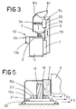
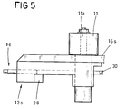
- the left vertical tool 11 illustrated purely by way of example since the two vertical tools are identical and equipped with the slide 12s having a horizontally-developing base on which the corresponding casing 13s is slidably constrained with relative pressing organs 14: the casing 13s is constrained inferiorly on a parallel relief couple 21 equipping the slide 12s to which a support cylinder 23 of a tool-bearing shaft 11a is slidably constrained, at the end closest to the work plane 2 and in a corresponding seating 22.
- the plane 15s interplaced between the casing 13s and the slide 12s has a greater mass than the slide 12s itself and exhibits a pair of slots 24 for the passage of the relief couple 21 constraining the casing 13s and a circular seating 25 for the passage of the tool-bearing shaft 11a.
- Parallel to the first casing 28 is a second casing 35, arranged by the side of the first casing and rigidly fixed to it and also to the tool-bearing group by means of a rigid central bar 36 which exhibits a third horizontal screw 37 screwably inserted in a relative third nut seating 38 made on a bridge 39 which is rigidly connected to the plane 15s in such a way as to permit a single and independent transversal movement, independent with respect to the tool 11 and to the casing 13s, and transversal with respect to the plane 2.
- This type of regulating structure is also made in the right vertical tool 10, apart from the first regulating screw 30 of the casing 13d since it is fixed to the slide 12d.
- the second casing 35 can also exhibit a fourth regulating screw 40 (illustrated by a broken line in figure 4) parallel to the previous ones and connected to the tool-bearing group 10a and 11a in such a way as to enable an axial height regulation with respect to the work plane 2; such regulation is effected thanks to a kinematic connectection between the screw 40 and the tool-bearing shaft 10a and 11a (not illustrated herein since of known type).
- a fourth regulating screw 40 illustrated by a broken line in figure 4
- the molding machine as it is structured herein functions in the following way: the operator, when he must newly set the machine tools, when a new work operation is about to begin or when a worn tool is to be substituted, merely has to substitute and reposition the lower horizontal 5 and right vertical 10 tools and according to the new dimensions of the workpiece 3, which are functions of the diameters D and D1 of the relative new tools and height H and breadth L of the workpiece 3.
- the setting is thus effected, after having opened the relative casings 8i, 13d and having substituted the tool 5, 10, the casing is repositioned with respect to the tools (so that the lower strike plane of the mobile guide G1 coincides with the line of the smallest diameter of the tool).
- the work plane and the mobile guide G1 are at a distance from the transport plane 2 which, concerning the horizontal tool 5, is equal to the entry height of the workpiece 3 minus the predetermined thickness t to be removed (or He - t of figure 1); regarding the vertical tool 10, the distances are equal to the entry breadth minus the thickness S to be removed, which is also predeterminable (or Le - S of figure 2).
- the operator goes on to define the settings of the left vertical tool 11 and those of the upper horizontal tool 6 which define the exit breadth and the exit height of the workpiece 3 from the station 1 (respectively final Lu and Hu of the workpiece 3), or the thickness not removed by the preceding tools.
- the phases are the same as the preceding except for the fact that it is possible subsequently also to regulate the height of the tool-bearing shaft 8sa with respect to the casing 8s.
- the operator can further regulate the tools 10 and 11 by acting on the relative fourth regulating screw 40 at the height of the tool 10 and 11 with respect to the work plane 2.
Landscapes
- Life Sciences & Earth Sciences (AREA)
- Engineering & Computer Science (AREA)
- Mechanical Engineering (AREA)
- Wood Science & Technology (AREA)
- Forests & Forestry (AREA)
- Milling, Drilling, And Turning Of Wood (AREA)
Applications Claiming Priority (2)
| Application Number | Priority Date | Filing Date | Title |
|---|---|---|---|
| ITBO920193 | 1992-05-21 | ||
| ITBO920193A IT1257800B (it) | 1992-05-21 | 1992-05-21 | Macchina scorniciatrice per la lavorazione del legno |
Publications (2)
| Publication Number | Publication Date |
|---|---|
| EP0571341A1 true EP0571341A1 (de) | 1993-11-24 |
| EP0571341B1 EP0571341B1 (de) | 1996-12-04 |
Family
ID=11338281
Family Applications (1)
| Application Number | Title | Priority Date | Filing Date |
|---|---|---|---|
| EP93830211A Expired - Lifetime EP0571341B1 (de) | 1992-05-21 | 1993-05-19 | Kehlmaschine für Holzbearbeitung |
Country Status (3)
| Country | Link |
|---|---|
| EP (1) | EP0571341B1 (de) |
| DE (1) | DE69306304T2 (de) |
| IT (1) | IT1257800B (de) |
Cited By (4)
| Publication number | Priority date | Publication date | Assignee | Title |
|---|---|---|---|---|
| DE19843725C1 (de) * | 1998-09-24 | 1999-12-09 | Michael Dickhut | Verfahren zur Aufständerung von stangenförmigen Gegenständen, insbesondere von Tannenbäumen, Vorrichtung zur Durchführung des Verfahrens sowie Ständer |
| DE102009022345A1 (de) * | 2009-05-15 | 2010-11-18 | Michael Weinig Ag | Hobeleinrichtung, insbesondere Abricht- oder Fügeeinrichtung, für eine Maschine zum Bearbeiten von Werkstücken aus Holz, Kunststoff und dergleichen |
| WO2012107909A3 (es) * | 2011-02-08 | 2012-11-01 | Felipe Garay Cava | Equipo y procedimiento de escuadradora doble para mecanizado lateral de materiales rígidos apilados |
| EP3025834A1 (de) * | 2014-11-25 | 2016-06-01 | Otto Martin Maschinenbau GmbH & Co. KG | Führungseinrichtung |
Families Citing this family (1)
| Publication number | Priority date | Publication date | Assignee | Title |
|---|---|---|---|---|
| DE19756503B4 (de) * | 1997-12-19 | 2007-09-27 | Michael Weinig Ag | Kehlmaschine |
Citations (7)
| Publication number | Priority date | Publication date | Assignee | Title |
|---|---|---|---|---|
| US1456864A (en) * | 1920-07-07 | 1923-05-29 | Woods Machine Co Sa | Side-head construction for matchers and the like |
| US4457350A (en) * | 1980-07-03 | 1984-07-03 | Finnila John S | Lumber planing machine |
| DE3443398A1 (de) * | 1984-11-28 | 1986-05-28 | Maschinenfabrik Reichenbacher GmbH, 8635 Dörfles-Esbach | Niederhalter fuer werkstuecke, insbesondere an fraesmaschinen |
| DE3903906A1 (de) * | 1989-02-10 | 1989-06-15 | Martin Otto Maschbau Gmbh | Vorrichtung an tischfraesmaschinen fuer holz- oder kunststoffbearbeitung |
| EP0385056A2 (de) * | 1989-03-03 | 1990-09-05 | Wilhelm Hirsch | Fräsmaschine zum Längsprofilieren von Rahmenhölzern für Fenster oder Türen |
| EP0458001A2 (de) * | 1990-05-24 | 1991-11-27 | SCM S.p.A. | Verbesserung an Kehlenmaschinen für die Holzbearbeitung |
| EP0458002A2 (de) * | 1990-05-24 | 1991-11-27 | SCM S.p.A. | Verbesserung an Kehlmaschinen für die Holzbearbeitung |
-
1992
- 1992-05-21 IT ITBO920193A patent/IT1257800B/it active IP Right Grant
-
1993
- 1993-05-19 EP EP93830211A patent/EP0571341B1/de not_active Expired - Lifetime
- 1993-05-19 DE DE69306304T patent/DE69306304T2/de not_active Expired - Fee Related
Patent Citations (7)
| Publication number | Priority date | Publication date | Assignee | Title |
|---|---|---|---|---|
| US1456864A (en) * | 1920-07-07 | 1923-05-29 | Woods Machine Co Sa | Side-head construction for matchers and the like |
| US4457350A (en) * | 1980-07-03 | 1984-07-03 | Finnila John S | Lumber planing machine |
| DE3443398A1 (de) * | 1984-11-28 | 1986-05-28 | Maschinenfabrik Reichenbacher GmbH, 8635 Dörfles-Esbach | Niederhalter fuer werkstuecke, insbesondere an fraesmaschinen |
| DE3903906A1 (de) * | 1989-02-10 | 1989-06-15 | Martin Otto Maschbau Gmbh | Vorrichtung an tischfraesmaschinen fuer holz- oder kunststoffbearbeitung |
| EP0385056A2 (de) * | 1989-03-03 | 1990-09-05 | Wilhelm Hirsch | Fräsmaschine zum Längsprofilieren von Rahmenhölzern für Fenster oder Türen |
| EP0458001A2 (de) * | 1990-05-24 | 1991-11-27 | SCM S.p.A. | Verbesserung an Kehlenmaschinen für die Holzbearbeitung |
| EP0458002A2 (de) * | 1990-05-24 | 1991-11-27 | SCM S.p.A. | Verbesserung an Kehlmaschinen für die Holzbearbeitung |
Non-Patent Citations (1)
| Title |
|---|
| PATENT ABSTRACTS OF JAPAN vol. 12, no. 478 (M-775)(3325) 14 December 1988 & JP-A-63 200 902 ( PURIMA ) 19 August 1988 * |
Cited By (4)
| Publication number | Priority date | Publication date | Assignee | Title |
|---|---|---|---|---|
| DE19843725C1 (de) * | 1998-09-24 | 1999-12-09 | Michael Dickhut | Verfahren zur Aufständerung von stangenförmigen Gegenständen, insbesondere von Tannenbäumen, Vorrichtung zur Durchführung des Verfahrens sowie Ständer |
| DE102009022345A1 (de) * | 2009-05-15 | 2010-11-18 | Michael Weinig Ag | Hobeleinrichtung, insbesondere Abricht- oder Fügeeinrichtung, für eine Maschine zum Bearbeiten von Werkstücken aus Holz, Kunststoff und dergleichen |
| WO2012107909A3 (es) * | 2011-02-08 | 2012-11-01 | Felipe Garay Cava | Equipo y procedimiento de escuadradora doble para mecanizado lateral de materiales rígidos apilados |
| EP3025834A1 (de) * | 2014-11-25 | 2016-06-01 | Otto Martin Maschinenbau GmbH & Co. KG | Führungseinrichtung |
Also Published As
| Publication number | Publication date |
|---|---|
| DE69306304D1 (de) | 1997-01-16 |
| ITBO920193A0 (it) | 1992-05-21 |
| EP0571341B1 (de) | 1996-12-04 |
| IT1257800B (it) | 1996-02-13 |
| ITBO920193A1 (it) | 1993-11-21 |
| DE69306304T2 (de) | 1997-06-12 |
Similar Documents
| Publication | Publication Date | Title |
|---|---|---|
| CN1088419C (zh) | 多主轴机床 | |
| CN106217503B (zh) | 一种全自动数控双头铣榫机 | |
| CN101559575A (zh) | 一种数控多功能平面磨床 | |
| CN105921825A (zh) | 用于齿轮加工机床的加工头和用于齿接工件,特别是蜗轴或齿条的方法 | |
| US8151669B2 (en) | Method of and device for producing band saw blades | |
| EP0571341B1 (de) | Kehlmaschine für Holzbearbeitung | |
| US20220063033A1 (en) | A sheet processing machine and a method for processing flat workpieces | |
| CN109176018A (zh) | 一种喷头数控加工机床 | |
| GB2130132A (en) | A stamping machine having a drum turret | |
| EP0458002B1 (de) | Verbesserung an Kehlmaschinen für die Holzbearbeitung | |
| EP0517168B1 (de) | Spanabhebende Bearbeitungseinheit | |
| GB2046170A (en) | Apparatus for cutting notches in plywood baseplates for the insertion of strip steel cutters | |
| EP3858542B1 (de) | Numerisch gesteuerte mehrspindeldrehmaschine | |
| US4993138A (en) | Tool milling machine or the like type complex processing machine | |
| CN205915541U (zh) | 一种双刀圆柱加工机床 | |
| EP0458001B1 (de) | Verbesserung an Kehlenmaschinen für die Holzbearbeitung | |
| JP2677819B2 (ja) | V字形状溝加工機 | |
| CN208895678U (zh) | 一种喷头加工夹具 | |
| CN101195280B (zh) | 一种垫块铣切方法及其实现该方法的垫块铣切机 | |
| CN205629478U (zh) | 一种立式精铣机 | |
| CN2383635Y (zh) | 木工机床的定位夹紧进给装置 | |
| JP2677820B2 (ja) | V字形状溝加工機を用いた中間折曲製品の加工方法 | |
| CN210879775U (zh) | 一种可调式切割机 | |
| CN214977992U (zh) | 一种带切割齐头功能的悬臂数控铣装置 | |
| JP2677821B2 (ja) | V字形状溝加工機 |
Legal Events
| Date | Code | Title | Description |
|---|---|---|---|
| PUAI | Public reference made under article 153(3) epc to a published international application that has entered the european phase |
Free format text: ORIGINAL CODE: 0009012 |
|
| AK | Designated contracting states |
Kind code of ref document: A1 Designated state(s): DE FR GB IT |
|
| 17P | Request for examination filed |
Effective date: 19931123 |
|
| 17Q | First examination report despatched |
Effective date: 19940427 |
|
| GRAG | Despatch of communication of intention to grant |
Free format text: ORIGINAL CODE: EPIDOS AGRA |
|
| GRAH | Despatch of communication of intention to grant a patent |
Free format text: ORIGINAL CODE: EPIDOS IGRA |
|
| GRAH | Despatch of communication of intention to grant a patent |
Free format text: ORIGINAL CODE: EPIDOS IGRA |
|
| GRAA | (expected) grant |
Free format text: ORIGINAL CODE: 0009210 |
|
| AK | Designated contracting states |
Kind code of ref document: B1 Designated state(s): DE FR GB IT |
|
| ITF | It: translation for a ep patent filed |
Owner name: BUGNION S.P.A. |
|
| REF | Corresponds to: |
Ref document number: 69306304 Country of ref document: DE Date of ref document: 19970116 |
|
| ET | Fr: translation filed | ||
| PLBE | No opposition filed within time limit |
Free format text: ORIGINAL CODE: 0009261 |
|
| STAA | Information on the status of an ep patent application or granted ep patent |
Free format text: STATUS: NO OPPOSITION FILED WITHIN TIME LIMIT |
|
| 26N | No opposition filed | ||
| REG | Reference to a national code |
Ref country code: GB Ref legal event code: 732E |
|
| REG | Reference to a national code |
Ref country code: FR Ref legal event code: TP |
|
| REG | Reference to a national code |
Ref country code: FR Ref legal event code: TP Free format text: CORRECTION |
|
| REG | Reference to a national code |
Ref country code: GB Ref legal event code: IF02 |
|
| PGFP | Annual fee paid to national office [announced via postgrant information from national office to epo] |
Ref country code: IT Payment date: 20090522 Year of fee payment: 17 Ref country code: FR Payment date: 20090519 Year of fee payment: 17 Ref country code: DE Payment date: 20090526 Year of fee payment: 17 |
|
| PGFP | Annual fee paid to national office [announced via postgrant information from national office to epo] |
Ref country code: GB Payment date: 20100324 Year of fee payment: 18 |
|
| REG | Reference to a national code |
Ref country code: FR Ref legal event code: ST Effective date: 20110131 |
|
| PG25 | Lapsed in a contracting state [announced via postgrant information from national office to epo] |
Ref country code: IT Free format text: LAPSE BECAUSE OF NON-PAYMENT OF DUE FEES Effective date: 20100519 |
|
| PG25 | Lapsed in a contracting state [announced via postgrant information from national office to epo] |
Ref country code: DE Free format text: LAPSE BECAUSE OF NON-PAYMENT OF DUE FEES Effective date: 20101201 |
|
| PG25 | Lapsed in a contracting state [announced via postgrant information from national office to epo] |
Ref country code: FR Free format text: LAPSE BECAUSE OF NON-PAYMENT OF DUE FEES Effective date: 20100531 |
|
| GBPC | Gb: european patent ceased through non-payment of renewal fee |
Effective date: 20110519 |
|
| PG25 | Lapsed in a contracting state [announced via postgrant information from national office to epo] |
Ref country code: GB Free format text: LAPSE BECAUSE OF NON-PAYMENT OF DUE FEES Effective date: 20110519 |