EP0571341A1 - A molding machine for woodwork - Google Patents
A molding machine for woodwork Download PDFInfo
- Publication number
- EP0571341A1 EP0571341A1 EP93830211A EP93830211A EP0571341A1 EP 0571341 A1 EP0571341 A1 EP 0571341A1 EP 93830211 A EP93830211 A EP 93830211A EP 93830211 A EP93830211 A EP 93830211A EP 0571341 A1 EP0571341 A1 EP 0571341A1
- Authority
- EP
- European Patent Office
- Prior art keywords
- tool
- plane
- casing
- slide
- workpiece
- Prior art date
- Legal status (The legal status is an assumption and is not a legal conclusion. Google has not performed a legal analysis and makes no representation as to the accuracy of the status listed.)
- Granted
Links
Images


Classifications
-
- B—PERFORMING OPERATIONS; TRANSPORTING
- B27—WORKING OR PRESERVING WOOD OR SIMILAR MATERIAL; NAILING OR STAPLING MACHINES IN GENERAL
- B27C—PLANING, DRILLING, MILLING, TURNING OR UNIVERSAL MACHINES FOR WOOD OR SIMILAR MATERIAL
- B27C1/00—Machines for producing flat surfaces, e.g. by rotary cutters; Equipment therefor
- B27C1/08—Machines for working several sides of work simultaneously
-
- B—PERFORMING OPERATIONS; TRANSPORTING
- B27—WORKING OR PRESERVING WOOD OR SIMILAR MATERIAL; NAILING OR STAPLING MACHINES IN GENERAL
- B27F—DOVETAILED WORK; TENONS; SLOTTING MACHINES FOR WOOD OR SIMILAR MATERIAL; NAILING OR STAPLING MACHINES
- B27F1/00—Dovetailed work; Tenons; Making tongues or grooves; Groove- and- tongue jointed work; Finger- joints
- B27F1/02—Making tongues or grooves, of indefinite length
- B27F1/06—Making tongues or grooves, of indefinite length simultaneously along opposite edges of a board
Definitions
- the invention relates to a molding machine used in the working of wood.
- the tools (which, along the feeding line are respectively defined as the lower horizontal, the right vertical, the left vertical and the upper horizontal) are covered by a protection casing also functioning as an aspirator of the sawings, and are equipped, each bilaterally and outside the casing, with pressing elements to maintain the workpiece in a guided position before, during and after its working; more precisely, the front presser is arranged in an inclined position to invite the workpiece towards the tool, while the posterior presser is positioned parallel to the plane and is at a distance from the plane depending on the thickness the finished workpiece is to have.
- each of the tools is supported by a relative positioning slide, mobile in an orthogonal direction to the work plane for the positioning of the tool, and is equipped with a casing to which the pressing organs are solidly and laterally connected, which casing is equipped with regulation means acting between the casing and the slide, which regulation means can vary the distance with respect to the work plane according to the reference diameter of the tool with a reading device associated to slide able to indicate, on a digital reading scale, the values of the relevant distances.
- the molding machine is more rapid and precise in the positioning of the tools, in in the change of shape, and works with a considerable precision.
- the improvement influences the design of the machine it derives from, giving rise to "hybrid" machines with costs that are relatively high.
- the aim of the present invention is thus to eliminate the above-mentioned drawbacks by providing a molding machine for wodd workpieces which is precise, rationalised with regard to all of the tool- and shape-change operations, so as to enable an improvement in the relative work operations.
- the molding machine in question is of the type which works on four sides of a plank of wood and comprises (see in particular figures 1 and 2) a station 1 disposed close to a horizontal reference and transport plane 2 for the four-sided working of the workpieces 3 supported on a relative base 4; naturally some parts of the machine have not been fully illustrated since they are bearing structures, and some devices used are already very well known.
- the station 1 essentially comprises four working tools for the workpieces 3 (see figures 1 and 2) which tools, following the advancement direction of the workpieces 3, (indicated by F in figures 1 and 2), are known as lower horizontal 5, right vertical 10, left vertical 11 and upper horizontal 6; the denomination indicates the side of the workpieces 3 that each single tool works on (or the plane to be worked on itself).
- Each of these tools is supported by corresponding slides 7i, 7s and 12d, 12s, which are positioned according to the tool supported and which enable the variation of the operative distance in an orthogonal direction to the work plane; apart from the guides 7 and 12, each of these four tools is equipped with a relative casing 8i, 8s and 13d, 13s to cover it.
- Pressing organs 9 and 14 are solid bilaterally to the casings 8s and 13s of the relative tools (left vertical 11 and upper horizontal 6), which pressing organs 9 and 14 permit the guiding and stabilising of the workpieces 3 for the relative work operations.
- the said pressing organs 9 and 14 can be constituted by strip couples 41, 42 for each tool, of which the front strip 41 is inclined with respect to the transport plane 2, while the back strip 42 is parallel with respect to the said transport plane 2 so as to permit the guiding or the invitation or the stabilising of the workpieces 3; while the right vertical tool 10 is equipped with a guide pair, of which one G stops the workpieces 3 and one G1 functions as a mobile reference in such a way as to enable relative variation in the distances according to the thickness of the shaving to be planed off.
- roller means arranged over all of the horizontal plane and constrained to a cross-bar T posteriorly disposed with respect to the transport plane 2 and aimed at permitting the drawing of the workpieces 3 from one tool to another.
- These roller means are constituted by wheels 43, made of steel or rubber, regularly distributed over all of the transport plane 2 so as to permit the workpieces 3 to be drawn.
- the upper horizontal tool 6 is regulatably mobile on the corresponding slide 7s and is equipped with a casing 8s solid to it to enable a variation to be made in the distance with respect to the plane to be worked on according to a reference diameter D of the tool and a height H of the workpiece 3.
- the horizontal tool 6 is supported by a vertical column 18, which is arranged posteriorly with respect to the transport plane 2 and is constrained, by means of vertical guides 19 defining the slide 7s, to the base 18; the casing 8s is is solidly constrained to the guides 19 and is also superiorly equipped with a sawdust and shaving aspirator and collector 8t.
- the horizontal support shaft 6a of the tool 6 is constrained, through the relative slide supports 20, to the guides 19 so as to permit a relative regulation between the upper horizontal tool 6 and the vertical column 18.
- the left vertical tool 11 illustrated purely by way of example since the two vertical tools are identical and equipped with the slide 12s having a horizontally-developing base on which the corresponding casing 13s is slidably constrained with relative pressing organs 14: the casing 13s is constrained inferiorly on a parallel relief couple 21 equipping the slide 12s to which a support cylinder 23 of a tool-bearing shaft 11a is slidably constrained, at the end closest to the work plane 2 and in a corresponding seating 22.
- the plane 15s interplaced between the casing 13s and the slide 12s has a greater mass than the slide 12s itself and exhibits a pair of slots 24 for the passage of the relief couple 21 constraining the casing 13s and a circular seating 25 for the passage of the tool-bearing shaft 11a.
- Parallel to the first casing 28 is a second casing 35, arranged by the side of the first casing and rigidly fixed to it and also to the tool-bearing group by means of a rigid central bar 36 which exhibits a third horizontal screw 37 screwably inserted in a relative third nut seating 38 made on a bridge 39 which is rigidly connected to the plane 15s in such a way as to permit a single and independent transversal movement, independent with respect to the tool 11 and to the casing 13s, and transversal with respect to the plane 2.
- This type of regulating structure is also made in the right vertical tool 10, apart from the first regulating screw 30 of the casing 13d since it is fixed to the slide 12d.
- the second casing 35 can also exhibit a fourth regulating screw 40 (illustrated by a broken line in figure 4) parallel to the previous ones and connected to the tool-bearing group 10a and 11a in such a way as to enable an axial height regulation with respect to the work plane 2; such regulation is effected thanks to a kinematic connectection between the screw 40 and the tool-bearing shaft 10a and 11a (not illustrated herein since of known type).
- a fourth regulating screw 40 illustrated by a broken line in figure 4
- the molding machine as it is structured herein functions in the following way: the operator, when he must newly set the machine tools, when a new work operation is about to begin or when a worn tool is to be substituted, merely has to substitute and reposition the lower horizontal 5 and right vertical 10 tools and according to the new dimensions of the workpiece 3, which are functions of the diameters D and D1 of the relative new tools and height H and breadth L of the workpiece 3.
- the setting is thus effected, after having opened the relative casings 8i, 13d and having substituted the tool 5, 10, the casing is repositioned with respect to the tools (so that the lower strike plane of the mobile guide G1 coincides with the line of the smallest diameter of the tool).
- the work plane and the mobile guide G1 are at a distance from the transport plane 2 which, concerning the horizontal tool 5, is equal to the entry height of the workpiece 3 minus the predetermined thickness t to be removed (or He - t of figure 1); regarding the vertical tool 10, the distances are equal to the entry breadth minus the thickness S to be removed, which is also predeterminable (or Le - S of figure 2).
- the operator goes on to define the settings of the left vertical tool 11 and those of the upper horizontal tool 6 which define the exit breadth and the exit height of the workpiece 3 from the station 1 (respectively final Lu and Hu of the workpiece 3), or the thickness not removed by the preceding tools.
- the phases are the same as the preceding except for the fact that it is possible subsequently also to regulate the height of the tool-bearing shaft 8sa with respect to the casing 8s.
- the operator can further regulate the tools 10 and 11 by acting on the relative fourth regulating screw 40 at the height of the tool 10 and 11 with respect to the work plane 2.
Abstract
Description
- The invention relates to a molding machine used in the working of wood.
- In the field of design and production of machines for the working of wood, and in particular molding machines, there is continual research for ways of improving the work quality of the machines, their precision and the speed with which the non-machine operative positioning operations can be carried out.
- In the case of the abovementioned machines, that is in machines predisposed for the working of all four faces of a plank of wood arriving from a feeding line, it has been noted that the tool-change times (or for a change of wood-shape) are very long and the work is laborious: the tools used, which are in the elementary and classic conformation of one for each side of the plank (with some variants for the types of work to be done), are arranged along a horizontal work plane. Drawing wheels (rubber or steel) are interpositioned between the tools and have their rotation axes parallel to the work plane and are connected in motion one to another by a posterior cross-piece: these wheels have the function of drawing the workpiece along the operative advancement direction, feeding it continuously to the tools.
- The tools (which, along the feeding line are respectively defined as the lower horizontal, the right vertical, the left vertical and the upper horizontal) are covered by a protection casing also functioning as an aspirator of the sawings, and are equipped, each bilaterally and outside the casing, with pressing elements to maintain the workpiece in a guided position before, during and after its working; more precisely, the front presser is arranged in an inclined position to invite the workpiece towards the tool, while the posterior presser is positioned parallel to the plane and is at a distance from the plane depending on the thickness the finished workpiece is to have.
- Recently it has been noted that the substitution of one or more of these tools, for a change of shape or profile, is lengthy and laborious: the operator must substitute the tools after removal of the protection casing, disengaging it with respect to the posterior cross-piece which supports it; then the operator must set the new tool on the same work plane (according to its new diameter), by means of special handwheels and using graduated scales situated on the machine itself, with which scales it is possible to control, by varying, the distance and/or the height of the rotation axis of the tool from the work plane. Once this phase has been carried it is then necessary to reposition the casing according to the new size and dimensions of the new workpiece.
- Thus it can be seen from the preceding summary description, that the substitution of each single tool brings about a work time which is rather long on the part of the operator, apart from the fact that the precision of the repositioning of the new tool and the pressers (casings) depends, in a great number of cases, on the operator's experience.
- To this end the present Applicant made an improvement in a molding machine (see Patent Application IT-3518A/90) in which it was envisaged that each of the tools is supported by a relative positioning slide, mobile in an orthogonal direction to the work plane for the positioning of the tool, and is equipped with a casing to which the pressing organs are solidly and laterally connected, which casing is equipped with regulation means acting between the casing and the slide, which regulation means can vary the distance with respect to the work plane according to the reference diameter of the tool with a reading device associated to slide able to indicate, on a digital reading scale, the values of the relevant distances.
- Thanks to this improvement, the molding machine is more rapid and precise in the positioning of the tools, in in the change of shape, and works with a considerable precision. As often happens, however, the improvement influences the design of the machine it derives from, giving rise to "hybrid" machines with costs that are relatively high.
- The aim of the present invention is thus to eliminate the above-mentioned drawbacks by providing a molding machine for wodd workpieces which is precise, rationalised with regard to all of the tool- and shape-change operations, so as to enable an improvement in the relative work operations.
- The technical characteristics of the invention, according to the above-mentioned aims, emerge clearly from the contents of the following claims, and the advantages of the invention will become more eviding during the detailed description that follows, made with reference to the enclosed drawings, which represent an embodiment which is purely in the form of a non-limiting example, and in which:
- figure 1 shows, in a schematic side-view with some parts removed better to evidence others, the molding machine object of the invention;
- figure 2 shows, in a schematic plan view from above, with some parts removed in order better to evidence others, the machine of figure 1;
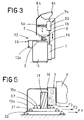
- figure 3 shows, in a side view with some parts in section and other removed in section, a detail of a tool of the machine of the preceding figures;
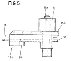
- figures 4 and 5 show respectively in a plan view from above and lateral with some parts removed in order better to evidence others, and other parts in section, a further tool of the machine of the previous figures;
- figure 6 shows a kinematic design of the movement groups of the tools of figures 5 and 6.
- With reference to the figures, the molding machine in question is of the type which works on four sides of a plank of wood and comprises (see in particular figures 1 and 2) a
station 1 disposed close to a horizontal reference andtransport plane 2 for the four-sided working of theworkpieces 3 supported on arelative base 4; naturally some parts of the machine have not been fully illustrated since they are bearing structures, and some devices used are already very well known. - The
station 1 essentially comprises four working tools for the workpieces 3 (see figures 1 and 2) which tools, following the advancement direction of theworkpieces 3, (indicated by F in figures 1 and 2), are known as lower horizontal 5, right vertical 10, left vertical 11 and upper horizontal 6; the denomination indicates the side of theworkpieces 3 that each single tool works on (or the plane to be worked on itself). Each of these tools is supported bycorresponding slides guides 7 and 12, each of these four tools is equipped with arelative casing -
Pressing organs casings organs workpieces 3 for the relative work operations. The saidpressing organs strip couples front strip 41 is inclined with respect to thetransport plane 2, while theback strip 42 is parallel with respect to the saidtransport plane 2 so as to permit the guiding or the invitation or the stabilising of theworkpieces 3; while the rightvertical tool 10 is equipped with a guide pair, of which one G stops theworkpieces 3 and one G1 functions as a mobile reference in such a way as to enable relative variation in the distances according to the thickness of the shaving to be planed off. - In figures 1 and 2 17 denotes roller means arranged over all of the horizontal plane and constrained to a cross-bar T posteriorly disposed with respect to the
transport plane 2 and aimed at permitting the drawing of theworkpieces 3 from one tool to another. These roller means are constituted bywheels 43, made of steel or rubber, regularly distributed over all of thetransport plane 2 so as to permit theworkpieces 3 to be drawn. - As can be seen in figure 3, the upper
horizontal tool 6 is regulatably mobile on thecorresponding slide 7s and is equipped with acasing 8s solid to it to enable a variation to be made in the distance with respect to the plane to be worked on according to a reference diameter D of the tool and a height H of theworkpiece 3. - More in detail, the
horizontal tool 6 is supported by avertical column 18, which is arranged posteriorly with respect to thetransport plane 2 and is constrained, by means ofvertical guides 19 defining theslide 7s, to thebase 18; thecasing 8s is is solidly constrained to theguides 19 and is also superiorly equipped with a sawdust and shaving aspirator andcollector 8t. As can be seen, again in figure 3, thehorizontal support shaft 6a of thetool 6 is constrained, through the relative slide supports 20, to theguides 19 so as to permit a relative regulation between the upperhorizontal tool 6 and thevertical column 18. - In figures 4 and 5, only the left
vertical tool 11 is visible, which is equipped, like the rightvertical tool 10, with amobile arrest plane 15s for theworkpiece 3, which is interplaced between theslides tools vertical tool 11, on thecasing 13s, on thetool 11 and on the saidarrest plane 15s, while with regard to the rightvertical tool 10 they only act on the tool itself and on the relative plane 15d to enable a variation to be made to both, in consecutive series or independently between successive and preceding, of the distance of the plane to be worked on according to a second reference diameter D1 of thetool 11 and the breadth L (for the upper left) or the breadth S (for the right vertical) of theworkpiece 3. - More precisely, the left
vertical tool 11, illustrated purely by way of example since the two vertical tools are identical and equipped with theslide 12s having a horizontally-developing base on which thecorresponding casing 13s is slidably constrained with relative pressing organs 14: thecasing 13s is constrained inferiorly on aparallel relief couple 21 equipping theslide 12s to which asupport cylinder 23 of a tool-bearingshaft 11a is slidably constrained, at the end closest to thework plane 2 and in acorresponding seating 22. Obviously theplane 15s interplaced between thecasing 13s and theslide 12s, theplane 15s has a greater mass than theslide 12s itself and exhibits a pair ofslots 24 for the passage of therelief couple 21 constraining thecasing 13s and acircular seating 25 for the passage of the tool-bearingshaft 11a. - The left
vertical tool 11 as it is structured equips the above-mentioned regulation means 16, which are constituted (see figures 4 and 5) by afirst casing 28 defining a part of theslide 12s; thecasing 28 is inferiorly arranged with respect to thetransport plane 2 and exhibits aplate 29 equipped with twoconstraint reliefs 21 of thecasing 13s and a first and secondhorizontal regulation screw 30 and 31: the first of thescrews 30 is screwably connected to a correspondingfirst nut seating 32 exhibited by thesaid base 4, arranged on the opposite side of the machine with respect to theslide 12s, so as to enable the movement from the outside of the protection casing of all of thecasing group 13s and pressing organs 14 - tool 11 -plane 15s; thesecond screw 31, parallel to the first, is screwably constrained at its internal end to asecond nut seating 33 made on asupport plate 34 defining the shaft-tool bearinggroup 11a and is aimed at permitting the movement, independently of the preceding setting, of the tool 11 -plane 15s group with respect to thecasing 13s. - Parallel to the
first casing 28 is asecond casing 35, arranged by the side of the first casing and rigidly fixed to it and also to the tool-bearing group by means of a rigidcentral bar 36 which exhibits a thirdhorizontal screw 37 screwably inserted in a relativethird nut seating 38 made on abridge 39 which is rigidly connected to theplane 15s in such a way as to permit a single and independent transversal movement, independent with respect to thetool 11 and to thecasing 13s, and transversal with respect to theplane 2. This type of regulating structure is also made in the rightvertical tool 10, apart from the first regulatingscrew 30 of thecasing 13d since it is fixed to theslide 12d. - The
second casing 35 can also exhibit a fourth regulating screw 40 (illustrated by a broken line in figure 4) parallel to the previous ones and connected to the tool-bearinggroup 10a and 11a in such a way as to enable an axial height regulation with respect to thework plane 2; such regulation is effected thanks to a kinematic connectection between thescrew 40 and the tool-bearingshaft 10a and 11a (not illustrated herein since of known type). - The molding machine as it is structured herein functions in the following way: the operator, when he must newly set the machine tools, when a new work operation is about to begin or when a worn tool is to be substituted, merely has to substitute and reposition the lower horizontal 5 and right vertical 10 tools and according to the new dimensions of the
workpiece 3, which are functions of the diameters D and D1 of the relative new tools and height H and breadth L of theworkpiece 3. The setting is thus effected, after having opened therelative casings 8i, 13d and having substituted thetool transport plane 2 which, concerning thehorizontal tool 5, is equal to the entry height of theworkpiece 3 minus the predetermined thickness t to be removed (or He - t of figure 1); regarding thevertical tool 10, the distances are equal to the entry breadth minus the thickness S to be removed, which is also predeterminable (or Le - S of figure 2). Once this first regulation has been effected, the operator goes on to define the settings of the leftvertical tool 11 and those of the upperhorizontal tool 6 which define the exit breadth and the exit height of theworkpiece 3 from the station 1 (respectively final Lu and Hu of the workpiece 3), or the thickness not removed by the preceding tools. Regarding the upper horizontal 6, the phases are the same as the preceding except for the fact that it is possible subsequently also to regulate the height of the tool-bearing shaft 8sa with respect to thecasing 8s. - As for the left
vertical tool 11, the regulation happens in three distinct phases, and for greater clarity these movements can be seen in figure 6, wherein the kinematic connection of the various elements is shown schematically: as soon as thetool 11 has been substituted with the new one, and thecasing 13s has been reapplied, the operator proceeds to the first regulation of thecasing 13s with the relativepressing organs 14 through thefirst screw 30 which causes the advancing or the retracting (see arow F1) of all of the casing-tool-plane groups at distance Lu; once this operation has been done the operator brings thetool 11 to the edge of the casing (see arrow 2) thanks to thesecond screw 31 beining behind it also theplane 15s, but no longer thecasing 13s. Finally the operator proceeds to the definitive setting of theplane 15s by using the third screw 37 (a function of thetool 11 diameter and indicated by F3) so as to arrange the edge of the seating at the edge of thetool 11 so as to permit a better lie of theworkpiece 3 in arrival. - Summarising, there occurs a regulation of the elements in series starting from the casing which time by time however distances the just-regulated element so as to enable a faster positioning of the successive elements.
- Naturally the operator can further regulate the
tools screw 40 at the height of thetool work plane 2.
Claims (6)
- A molding machine for working wood workpieces on four sides comprising a station (1) disposed near to a horizontal reference and transport plane (2) of the said workpieces (3), supported by a relative base (4), characterised in that said station (1) comprises:- a first tool (5) destined to work on a lower horizontal surface of the said workpiece (3) and supported by a corresponding slide (7i) aimed at varying the operative distance of the said tool (5) in an orthogonal direction to a plane to be worked on; the said tool (5) being equipped with a casing (8i) for covering and being regulatably mobile on the corresponding slide (7i) so as to permit of varying the tool (5) with respect to the said plane to be worked on according to a diameter (D);- a second tool (10) destined to work on a right vertical surface of the said workpiece (3), supported by a corresponding slide (12d) destined to vary the operative distance in an orthogonal direction to the plane to be worked on and equipped with a covering case (13d) bilaterally to which case (13d) are respectively positioned a fixed reference guide (G) for the workpiece (3) and a mobile reference guide (G1) so as to permit of relative variation of the distance according to a thickness (S) of wood to be removed; the second tool (10) being equipped with a mobile meeting plane (15d) for the said workpiece (3) supported by the said slide (12d); regulating means (16) being provided on said slide (12d) and acting on said tool (10) and said meeting plane (15d) so as to permit of varying, in consequential series on the tool (10) and plane (15d) and independently of successive and preceding operations, the distance from the said plane to be worked on according to a second reference diameter (D1) of said tool (10) and said thickness (S) of said workpiece (3);- a third tool (11) designed to work on a left vertical surface of the said workpiece (3), supported by a corresponding slide (12s) aimed at varying the operative distance in an orthogonal direction to the plane to be word on and equipped with a covering casing (13s) to which corresponding pressing organs (14) are bilaterally solid; said third tool (1) being equipped with a mobile meeting plane (15s) for said workpiece (3) supported by said slide (12s); regulation means (16) being provided on said third tool (11) and acting on said casing (13s), on said tool (11) and on said plane (15s) in such a way as to permit of varying, in consequential series on the tool (11) and casing (13s) and independently of successive and preceding operations, the distance from the said plane to be worked on according to a second reference diameter (D1) odf said tool (11) and a breadth (L) of said workpiece (3);- a fourth tool (6) destined to work on an upper horizontal surface of said workpiece (3) and supported by a corresponding slide (7s) aimed at varying the operative distance of the said tool (6) in an orthogonal direction to the plane to be worked on; said tool (6) being equipped with a casing (8s) bilaterally to which pressing organs are solid, which pressing organs (9) are aimed at permitting guiding and stabilising of said workpiece (3) during said working; said tool (6) being regulatably mobile on the corresponding slide (7s) and equipped with said casing (8s) solid to said slide (7s) so as to permit of varying the distances with respect to said plane to be worked on according to a reference diameter (D) of said tool (6) and a height (H) of said workpiece (3);- roller means (17) being provided for all said horizontal plane, constrained to a cross-piece (T) which is posteriorly arranged with respect to said plane (2), said roller means (17) being aimed at permitting a drawing of said workpiece (3) from a said tool to another.
- A molding machine as in claim 1, characterised in that said fourth tool (6) is supported by a vertical column (18) arranged posteriorly with respect to said plane (2) and constrained, by means of vertical guides (19) defining the said slide (7s), to said base (18) and to which tool (6) said casing (8s) is solidly constrained; the horizontal support shaft (6a) of said tool (6) being constrained through relative slide supports (20) to said guides (19) so as to permit of relative regulation between said tool (6) and said column (18).
- A molding machine as in claim 1, characterised in that said third vertical tool (11) is equipped with said horizontal-base slide (12s) on which the corresponding casing (13s) is slidably constrained with relative said pressing organs (14); said casing (13s) being inferiorly constrained on a couple of parallel reliefs (21) with which said slide (12s) is equipped; also slidably constrained to said slide (12s), at an end close to said work plane (2) and in a corresponding seating (22), is a support cylinder (23) of a tool-bearing shaft (11a) and, interplaced between said casing (13s) and said slide (12s) is said plane (15s), which has a greater mass than that of the slide (12s) and exhibits a pair of slots (24) for the passage of said constraining reliefs (21) of said casing (13s) and a seating (25) for a passage of said tool-bearing shaft (11a).
- A molding machine as in claim 1, characterised in that the said regulating means (16) of said second and third tools (10, 11) are constituted respectively for each tool (10, 11) by:- a first protection casing (28) defining part of said slide (12d, 12s), arranged inferiorly with respect to said plane (2) and exhibiting a second horizontal regulating screw (31) screwably constrained at an internal end to a second nut seating (339 made on a support plate (34) defining the tool-bearing shaft group (11a) and aimed at permitting of indepenedent movement of the said tool (10, 11) - plane (15d, 15s) group with respect to said casing (13d, 13s);- a second protection casing (35) parallel to the first casing (28) arranged by a side of said first casing (28) and fixed rigidly to it and to said tool-bearing group (10a, 11a) by means of a rigid central bar (36) and exhibiting at least one third horizontal screw (37) screwably inserted in a relative third nut seating (38) made on a bridge (39) rigidly connected to said plane (15d, 15s) so as to permit of a single and independent transversal movement, being independent to said tool (10, 11) and said casing (13d, 13s) and transversal with respect to said plane (2).
- A molding machine as in claim 4, characterised in that said first protection casing (28) for regulation of said third tool (11) exhibits a plate (29) equipped with two reliefs (21) for constraining said casing (13s) and a first screw (30) screwably connected to a corresponding first nut seating (32) presented by said base (4), which first screw (30) is arranged on an opposite side with respect to said slide (12s), so as to permit of moving, from outside said protection casing (28), all of the casing (13s) and the pressing organs (14) - tool (11) - plane (15s) group.
- A molding machine as in claim 4, characterised in that said second protection casing (35) exhibits a fourth regulation screw (40) which is parallel to the preceding regulation screws and is connected to said tool-bearing group (11a) so as to permit of axial height regulation with respect to said plane (2).
Applications Claiming Priority (2)
| Application Number | Priority Date | Filing Date | Title |
|---|---|---|---|
| ITBO920193A IT1257800B (en) | 1992-05-21 | 1992-05-21 | MOUNTING MACHINE FOR WOOD WORKING |
| ITBO920193 | 1992-05-21 |
Publications (2)
| Publication Number | Publication Date |
|---|---|
| EP0571341A1 true EP0571341A1 (en) | 1993-11-24 |
| EP0571341B1 EP0571341B1 (en) | 1996-12-04 |
Family
ID=11338281
Family Applications (1)
| Application Number | Title | Priority Date | Filing Date |
|---|---|---|---|
| EP93830211A Expired - Lifetime EP0571341B1 (en) | 1992-05-21 | 1993-05-19 | A molding machine for woodwork |
Country Status (3)
| Country | Link |
|---|---|
| EP (1) | EP0571341B1 (en) |
| DE (1) | DE69306304T2 (en) |
| IT (1) | IT1257800B (en) |
Cited By (4)
| Publication number | Priority date | Publication date | Assignee | Title |
|---|---|---|---|---|
| DE19843725C1 (en) * | 1998-09-24 | 1999-12-09 | Michael Dickhut | Method of supporting Christmas tree |
| DE102009022345A1 (en) * | 2009-05-15 | 2010-11-18 | Michael Weinig Ag | Smoothing plane device e.g. trimming device, for trimming of wooden work-piece, has entering channel limited by upper guidance spacer at side that lies opposite to truing table for truing work-piece |
| WO2012107909A3 (en) * | 2011-02-08 | 2012-11-01 | Felipe Garay Cava | Double squaring method and device for the lateral machining of stacked rigid materials |
| EP3025834A1 (en) * | 2014-11-25 | 2016-06-01 | Otto Martin Maschinenbau GmbH & Co. KG | Guiding device |
Families Citing this family (1)
| Publication number | Priority date | Publication date | Assignee | Title |
|---|---|---|---|---|
| DE19756503B4 (en) * | 1997-12-19 | 2007-09-27 | Michael Weinig Ag | moulder |
Citations (7)
| Publication number | Priority date | Publication date | Assignee | Title |
|---|---|---|---|---|
| US1456864A (en) * | 1920-07-07 | 1923-05-29 | Woods Machine Co Sa | Side-head construction for matchers and the like |
| US4457350A (en) * | 1980-07-03 | 1984-07-03 | Finnila John S | Lumber planing machine |
| DE3443398A1 (en) * | 1984-11-28 | 1986-05-28 | Maschinenfabrik Reichenbacher GmbH, 8635 Dörfles-Esbach | Hold-down device for workpieces, in particular on routing machines |
| DE3903906A1 (en) * | 1989-02-10 | 1989-06-15 | Martin Otto Maschbau Gmbh | Apparatus on spindle-shaping machines for working wood or plastic |
| EP0385056A2 (en) * | 1989-03-03 | 1990-09-05 | Wilhelm Hirsch | Milling machine for longitudinally profiling wooden frame members for windows or doors |
| EP0458002A2 (en) * | 1990-05-24 | 1991-11-27 | SCM S.p.A. | Improvement in moulding machines for woodworking |
| EP0458001A2 (en) * | 1990-05-24 | 1991-11-27 | SCM S.p.A. | Improvement in moulding machines for woodworking |
-
1992
- 1992-05-21 IT ITBO920193A patent/IT1257800B/en active IP Right Grant
-
1993
- 1993-05-19 EP EP93830211A patent/EP0571341B1/en not_active Expired - Lifetime
- 1993-05-19 DE DE69306304T patent/DE69306304T2/en not_active Expired - Fee Related
Patent Citations (7)
| Publication number | Priority date | Publication date | Assignee | Title |
|---|---|---|---|---|
| US1456864A (en) * | 1920-07-07 | 1923-05-29 | Woods Machine Co Sa | Side-head construction for matchers and the like |
| US4457350A (en) * | 1980-07-03 | 1984-07-03 | Finnila John S | Lumber planing machine |
| DE3443398A1 (en) * | 1984-11-28 | 1986-05-28 | Maschinenfabrik Reichenbacher GmbH, 8635 Dörfles-Esbach | Hold-down device for workpieces, in particular on routing machines |
| DE3903906A1 (en) * | 1989-02-10 | 1989-06-15 | Martin Otto Maschbau Gmbh | Apparatus on spindle-shaping machines for working wood or plastic |
| EP0385056A2 (en) * | 1989-03-03 | 1990-09-05 | Wilhelm Hirsch | Milling machine for longitudinally profiling wooden frame members for windows or doors |
| EP0458002A2 (en) * | 1990-05-24 | 1991-11-27 | SCM S.p.A. | Improvement in moulding machines for woodworking |
| EP0458001A2 (en) * | 1990-05-24 | 1991-11-27 | SCM S.p.A. | Improvement in moulding machines for woodworking |
Non-Patent Citations (1)
| Title |
|---|
| PATENT ABSTRACTS OF JAPAN vol. 12, no. 478 (M-775)(3325) 14 December 1988 & JP-A-63 200 902 ( PURIMA ) 19 August 1988 * |
Cited By (4)
| Publication number | Priority date | Publication date | Assignee | Title |
|---|---|---|---|---|
| DE19843725C1 (en) * | 1998-09-24 | 1999-12-09 | Michael Dickhut | Method of supporting Christmas tree |
| DE102009022345A1 (en) * | 2009-05-15 | 2010-11-18 | Michael Weinig Ag | Smoothing plane device e.g. trimming device, for trimming of wooden work-piece, has entering channel limited by upper guidance spacer at side that lies opposite to truing table for truing work-piece |
| WO2012107909A3 (en) * | 2011-02-08 | 2012-11-01 | Felipe Garay Cava | Double squaring method and device for the lateral machining of stacked rigid materials |
| EP3025834A1 (en) * | 2014-11-25 | 2016-06-01 | Otto Martin Maschinenbau GmbH & Co. KG | Guiding device |
Also Published As
| Publication number | Publication date |
|---|---|
| DE69306304T2 (en) | 1997-06-12 |
| DE69306304D1 (en) | 1997-01-16 |
| EP0571341B1 (en) | 1996-12-04 |
| IT1257800B (en) | 1996-02-13 |
| ITBO920193A1 (en) | 1993-11-21 |
| ITBO920193A0 (en) | 1992-05-21 |
Similar Documents
| Publication | Publication Date | Title |
|---|---|---|
| CN1088419C (en) | Multiple main axle machine tool | |
| CN106217503B (en) | A kind of full-automatic numerical control double end tenon milling machine | |
| CN101559575A (en) | Numerically controlled multi-functional surface grinding machine | |
| CN105921825A (en) | Machining head for a gear cutting machine and method for toothing a workpiece, in particular a worm shaft or toothed rack | |
| EP0571341B1 (en) | A molding machine for woodwork | |
| US20220063033A1 (en) | A sheet processing machine and a method for processing flat workpieces | |
| CN109176018A (en) | A kind of spray head numerical control machine tool | |
| GB2130132A (en) | A stamping machine having a drum turret | |
| EP0458002B1 (en) | Improvement in moulding machines for woodworking | |
| CN201161464Y (en) | Space block milling and cutting machine | |
| EP0517168B1 (en) | Chip-forming machining unit | |
| GB2046170A (en) | Apparatus for cutting notches in plywood baseplates for the insertion of strip steel cutters | |
| EP3858542B1 (en) | Numerically controlled multi-spindle lathe | |
| US4993138A (en) | Tool milling machine or the like type complex processing machine | |
| CN205915541U (en) | Double knives cylinder machine tool | |
| EP0458001B1 (en) | Improvement in moulding machines for woodworking | |
| CN208895678U (en) | A kind of spray head clamp for machining | |
| JP2677819B2 (en) | V-shaped grooving machine | |
| CN205629478U (en) | Vertical finish -milling machine | |
| CN2383635Y (en) | Positioning clamping feeding device for woodworking machine tools | |
| JP2677820B2 (en) | Processing method for intermediate bent products using V-shaped groove processing machine | |
| CN210879775U (en) | Adjustable cutting machine | |
| CN214977992U (en) | Cantilever numerical control milling device with cutting and head aligning functions | |
| JP2677821B2 (en) | V-shaped grooving machine | |
| CN212444088U (en) | High-speed numerical control drilling and milling machining center |
Legal Events
| Date | Code | Title | Description |
|---|---|---|---|
| PUAI | Public reference made under article 153(3) epc to a published international application that has entered the european phase |
Free format text: ORIGINAL CODE: 0009012 |
|
| AK | Designated contracting states |
Kind code of ref document: A1 Designated state(s): DE FR GB IT |
|
| 17P | Request for examination filed |
Effective date: 19931123 |
|
| 17Q | First examination report despatched |
Effective date: 19940427 |
|
| GRAG | Despatch of communication of intention to grant |
Free format text: ORIGINAL CODE: EPIDOS AGRA |
|
| GRAH | Despatch of communication of intention to grant a patent |
Free format text: ORIGINAL CODE: EPIDOS IGRA |
|
| GRAH | Despatch of communication of intention to grant a patent |
Free format text: ORIGINAL CODE: EPIDOS IGRA |
|
| GRAA | (expected) grant |
Free format text: ORIGINAL CODE: 0009210 |
|
| AK | Designated contracting states |
Kind code of ref document: B1 Designated state(s): DE FR GB IT |
|
| ITF | It: translation for a ep patent filed |
Owner name: BUGNION S.P.A. |
|
| REF | Corresponds to: |
Ref document number: 69306304 Country of ref document: DE Date of ref document: 19970116 |
|
| ET | Fr: translation filed | ||
| PLBE | No opposition filed within time limit |
Free format text: ORIGINAL CODE: 0009261 |
|
| STAA | Information on the status of an ep patent application or granted ep patent |
Free format text: STATUS: NO OPPOSITION FILED WITHIN TIME LIMIT |
|
| 26N | No opposition filed | ||
| REG | Reference to a national code |
Ref country code: GB Ref legal event code: 732E |
|
| REG | Reference to a national code |
Ref country code: FR Ref legal event code: TP |
|
| REG | Reference to a national code |
Ref country code: FR Ref legal event code: TP Free format text: CORRECTION |
|
| REG | Reference to a national code |
Ref country code: GB Ref legal event code: IF02 |
|
| PGFP | Annual fee paid to national office [announced via postgrant information from national office to epo] |
Ref country code: IT Payment date: 20090522 Year of fee payment: 17 Ref country code: FR Payment date: 20090519 Year of fee payment: 17 Ref country code: DE Payment date: 20090526 Year of fee payment: 17 |
|
| PGFP | Annual fee paid to national office [announced via postgrant information from national office to epo] |
Ref country code: GB Payment date: 20100324 Year of fee payment: 18 |
|
| REG | Reference to a national code |
Ref country code: FR Ref legal event code: ST Effective date: 20110131 |
|
| PG25 | Lapsed in a contracting state [announced via postgrant information from national office to epo] |
Ref country code: IT Free format text: LAPSE BECAUSE OF NON-PAYMENT OF DUE FEES Effective date: 20100519 |
|
| PG25 | Lapsed in a contracting state [announced via postgrant information from national office to epo] |
Ref country code: DE Free format text: LAPSE BECAUSE OF NON-PAYMENT OF DUE FEES Effective date: 20101201 |
|
| PG25 | Lapsed in a contracting state [announced via postgrant information from national office to epo] |
Ref country code: FR Free format text: LAPSE BECAUSE OF NON-PAYMENT OF DUE FEES Effective date: 20100531 |
|
| GBPC | Gb: european patent ceased through non-payment of renewal fee |
Effective date: 20110519 |
|
| PG25 | Lapsed in a contracting state [announced via postgrant information from national office to epo] |
Ref country code: GB Free format text: LAPSE BECAUSE OF NON-PAYMENT OF DUE FEES Effective date: 20110519 |