EP3858542B1 - Numerically controlled multi-spindle lathe - Google Patents
Numerically controlled multi-spindle lathe Download PDFInfo
- Publication number
- EP3858542B1 EP3858542B1 EP21153064.7A EP21153064A EP3858542B1 EP 3858542 B1 EP3858542 B1 EP 3858542B1 EP 21153064 A EP21153064 A EP 21153064A EP 3858542 B1 EP3858542 B1 EP 3858542B1
- Authority
- EP
- European Patent Office
- Prior art keywords
- carriage
- translation axis
- lathe
- base
- centers
- Prior art date
- Legal status (The legal status is an assumption and is not a legal conclusion. Google has not performed a legal analysis and makes no representation as to the accuracy of the status listed.)
- Active
Links
- 238000003754 machining Methods 0.000 claims description 9
- 230000001681 protective effect Effects 0.000 claims description 4
- 238000004904 shortening Methods 0.000 claims description 3
- 230000001360 synchronised effect Effects 0.000 claims 1
- 230000001133 acceleration Effects 0.000 description 4
- 230000005484 gravity Effects 0.000 description 2
- 238000004519 manufacturing process Methods 0.000 description 2
- 230000005540 biological transmission Effects 0.000 description 1
- 238000010276 construction Methods 0.000 description 1
- 229910001234 light alloy Inorganic materials 0.000 description 1
- 238000004804 winding Methods 0.000 description 1
- 239000002023 wood Substances 0.000 description 1
Images


Classifications
-
- B—PERFORMING OPERATIONS; TRANSPORTING
- B23—MACHINE TOOLS; METAL-WORKING NOT OTHERWISE PROVIDED FOR
- B23Q—DETAILS, COMPONENTS, OR ACCESSORIES FOR MACHINE TOOLS, e.g. ARRANGEMENTS FOR COPYING OR CONTROLLING; MACHINE TOOLS IN GENERAL CHARACTERISED BY THE CONSTRUCTION OF PARTICULAR DETAILS OR COMPONENTS; COMBINATIONS OR ASSOCIATIONS OF METAL-WORKING MACHINES, NOT DIRECTED TO A PARTICULAR RESULT
- B23Q39/00—Metal-working machines incorporating a plurality of sub-assemblies, each capable of performing a metal-working operation
- B23Q39/04—Metal-working machines incorporating a plurality of sub-assemblies, each capable of performing a metal-working operation the sub-assemblies being arranged to operate simultaneously at different stations, e.g. with an annular work-table moved in steps
- B23Q39/042—Metal-working machines incorporating a plurality of sub-assemblies, each capable of performing a metal-working operation the sub-assemblies being arranged to operate simultaneously at different stations, e.g. with an annular work-table moved in steps with circular arrangement of the sub-assemblies
- B23Q39/044—Metal-working machines incorporating a plurality of sub-assemblies, each capable of performing a metal-working operation the sub-assemblies being arranged to operate simultaneously at different stations, e.g. with an annular work-table moved in steps with circular arrangement of the sub-assemblies having at least one tool station cooperating with each work holder, e.g. multi-spindle lathes
-
- B—PERFORMING OPERATIONS; TRANSPORTING
- B23—MACHINE TOOLS; METAL-WORKING NOT OTHERWISE PROVIDED FOR
- B23B—TURNING; BORING
- B23B3/00—General-purpose turning-machines or devices, e.g. centre lathes with feed rod and lead screw; Sets of turning-machines
- B23B3/30—Turning-machines with two or more working-spindles, e.g. in fixed arrangement
- B23B3/32—Turning-machines with two or more working-spindles, e.g. in fixed arrangement for performing identical operations simultaneously on two or more workpieces
-
- B—PERFORMING OPERATIONS; TRANSPORTING
- B23—MACHINE TOOLS; METAL-WORKING NOT OTHERWISE PROVIDED FOR
- B23Q—DETAILS, COMPONENTS, OR ACCESSORIES FOR MACHINE TOOLS, e.g. ARRANGEMENTS FOR COPYING OR CONTROLLING; MACHINE TOOLS IN GENERAL CHARACTERISED BY THE CONSTRUCTION OF PARTICULAR DETAILS OR COMPONENTS; COMBINATIONS OR ASSOCIATIONS OF METAL-WORKING MACHINES, NOT DIRECTED TO A PARTICULAR RESULT
- B23Q39/00—Metal-working machines incorporating a plurality of sub-assemblies, each capable of performing a metal-working operation
- B23Q39/04—Metal-working machines incorporating a plurality of sub-assemblies, each capable of performing a metal-working operation the sub-assemblies being arranged to operate simultaneously at different stations, e.g. with an annular work-table moved in steps
-
- B—PERFORMING OPERATIONS; TRANSPORTING
- B23—MACHINE TOOLS; METAL-WORKING NOT OTHERWISE PROVIDED FOR
- B23Q—DETAILS, COMPONENTS, OR ACCESSORIES FOR MACHINE TOOLS, e.g. ARRANGEMENTS FOR COPYING OR CONTROLLING; MACHINE TOOLS IN GENERAL CHARACTERISED BY THE CONSTRUCTION OF PARTICULAR DETAILS OR COMPONENTS; COMBINATIONS OR ASSOCIATIONS OF METAL-WORKING MACHINES, NOT DIRECTED TO A PARTICULAR RESULT
- B23Q39/00—Metal-working machines incorporating a plurality of sub-assemblies, each capable of performing a metal-working operation
- B23Q2039/008—Machines of the lathe type
Definitions
- the present invention relates to the field of machine tools. More in particular, the invention relates to the field of numerically controlled lathes.
- elongated workpieces for example furniture components, made of wood, plastic, light alloys or the like
- the use of numerically controlled lathes and copying lathes is well known.
- multi-spindle copying lathes are known, which allow working contemporaneously a plurality of workpieces supported by a plurality of centers and tailstocks.
- the tools machining in parallel the plurality of workpieces are controlled through a template reproducing the shape of the product to be manufactured.
- a numerically controlled multi-spindle lathe is known from US 6 203 478 B1 , on which the preamble of appended claim 1 is based.
- a numerically controlled multi-spindle lathe is provided with a new configuration.
- the lathe comprises a bearing structure with a base extending according to a first translation axis.
- the lathe further comprises a plurality of pairs of turning members for rotating the workpieces.
- Each pair comprises a center and a tailstock that are coaxial with each other and define a respective rotation axis for the workpieces.
- Each center is motorized and the distance between centers and tailstocks is adjustable. Motorization can be provided by a single motor with transmission members, or by a plurality of motors, each of which can rotate one or more centers.
- the motor, or each motor, for rotating the centers may be a numerically controlled motor, so as to impart a numerically controlled rotation to each workpiece.
- the configuration is preferably such as identically to machine identical workpieces supported by the pairs of centers and tailstocks. To this end, the pairs of centers and tailstocks rotate synchronously.
- the lathe further comprises a first carriage guided on first guides that are integral with the base and extend in the direction of the first translation axis.
- the first carriage is advantageously provided with a numerically controlled movement along the first guides according to the first translation axis.
- the lathe further comprises a second carriage, supported by the first carriage and movable with a numerically controlled movement with respect to the first carriage.
- second guides are provided, extending in the direction of a second translation axis, orthogonal to the first translation axis.
- the second carriage may be directly supported by the first carriage, but it is also possible to provide a further intermediate carriage between the first carriage and the second carriage, so as to have a further translation axis.
- the choice between one configuration and the other can be based, for example, on the number of movements that the tools shall perform with respect to the workpieces.
- the lathe also comprises a plurality of spindles with parallel axes, supported by the second carriage and adapted to rotate tools configured to work simultaneously workpieces mounted between the centers and the tailstocks.
- the number of spindles is typically equal to the number of pairs of centers and tailstocks.
- the spindles may be suitably rotate synchronously.
- the number of pairs of centers and tailstocks can be twice the number of spindles, so that each tool supported by a spindle can machine two parallel workpieces simultaneously, by arranging the tool rotation axis in intermediate position between the rotation axes of the two workpieces to be machined simultaneously.
- machining can be performed by using spindles rotating around axes parallel to the rotation axes of the workpieces.
- the tools may have such a dimension (typically a diameter) so as to simultaneously machine two adjacent workpieces.
- the spindles may be provided with two translation movements according to two axes that are orthogonal to each other and to the rotation axis of the pairs of turning members for rotating the workpieces (centers and tailstocks).
- the first movement, orthogonal to the plane of lying of the rotation axes of the turning members for rotating the workpieces, is a numerically controlled movement towards the workpieces.
- the second movement, parallel to the plane of lying of the rotation axes of the turning members for rotating the workpieces may be a numerically controlled movement, or simply an adjustment movement for aligning each of the rotation axes of the spindles with one of the rotation axes of the turning members for rotating the workpieces, or for bringing them to an intermediate position between two rotation axes of two adjacent workpieces, for simultaneously machining these two workpieces.
- the lathe structure is such as to have highly stiff guiding systems, thus allowing the carriages, in particular the second carriage, to move with high accelerations. This allows shortening the working cycles and increasing the lathe productivity.
- the base fixed on the ground, to which the first guides for the first carriage are fastened allows stiffening the structure and allows high accelerations of the second carriage along the second translation axis.
- the movement along the first translation axis is typically parallel to the rotation axis of the centers and tailstocks, i.e. to the rotation axis of the workpieces. This movement is therefore parallel to the longitudinal extension of the workpieces.
- the movement along the second translation axis is a movement towards, and away from, the rotation axis of centers and tailstocks, i.e. orthogonal to this axis.
- the second guides are integral with the second carriage and preferably comprise a pair of guides that are spaced from each other in a direction orthogonal to the first translation axis and to the second translation axis.
- first translation axis and the second translation axis are horizontal
- the centers and the tailstocks define a plurality of rotation axes for the workpieces lying on a vertical plane, parallel to the first translation axis and orthogonal to the second translation axis.
- the lathe base comprises an upper side and two side walls, extending in the direction of the first translation axis.
- the first guides are applied on a first side wall of the base, and the first carriage forms a movable upright adj acent to the first side wall of the base and extending vertically beyond the upper surface of the base.
- the first guides comprise a pair of guides, whose center-to-center distance is equal to at least 50% of the height of the base, and preferably to at least 70% of the height of the base.
- the center-to-center distance is preferably the largest possible with respect to the height of the base, taking into account any construction constraint. In this way, a significant constraint reaction is achieved, in particular a constraint reaction torque around the first translation axis, adapted to withstand high dynamic stresses generated by the accelerations of the second carriage moving along the second translation axis.
- the center-to-center distance between the pair of first guides is greater than 300 mm, preferably greater than 400 mm and, more preferably, is comprised between 450 mm and 550 mm.
- the base height, the distance between the axes of centers and tailstocks and the number of centers and tailstocks are chosen so that an operator can load the workpieces easily.
- the base comprises a conveyor for collecting the chips that are formed while machining the workpieces, which is arranged on the upper side of the base, for example in a lowered area of the upper side.
- the conveyor can move parallel to the first translation axis, but it is also possible to use a conveyor, whose width extends parallel to the first translation axis and which moves in the direction of the second translation axis.
- the tailstocks are supported by an upright movable parallel to the first translation axis, to adjust the distance between the centers and the tailstocks.
- the centers are supported by an upright that is fixed with respect to the base. In this way, a simpler configuration is provided, as the motors of the centers are supported by the fixed upright. A reverse arrangement is also possible.
- the movable upright supporting the tailstocks may be advantageously guided on lower guides integral with the base and parallel to the first guides, and, if necessary, on upper guides supported by the bearing structure above the base.
- the lathe can comprise a flexible protective wall, approximately parallel to the first translation axis and approximately orthogonal to the second translation axis.
- the wall separates a machining area, where the centers and the tailstocks, as well as the chips collecting conveyor, if any, are arranged, from a protected back area, where the first carriage and the respective first guides are arranged.
- the second carriage may extend through the flexible wall to bring the tools into working position.
- the lathe comprises a third carriage, interposed between the first carriage and the second carriage.
- the second carriage is supported by the third carriage and is movable with respect to the third carriage along the second translation axis.
- the third carriage is supported by the first carriage and is movable along a third translation axis with a numerically controlled translation movement.
- the third translation axis is preferably orthogonal to the first translation axis and to the second translation axis. If the first two translation axes are horizontal, the third translation axis is vertical.
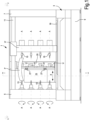
- FIG. 1-4 A first embodiment of a multi-spindle lathe is shown in Figs. 1-4 .
- the lathe is indicated with number 1 and comprises a bearing structure 3.
- the bearing structure 3 comprises a first vertical upright 5 and a second vertical upright 7, rigidly connected to a lower horizontal base 9.
- the uprights 5 and 7 are connected, at the top, by a horizontal crossbar 11.
- a plurality of centers 13 are supported by the upright 5. Each center is associated with a tailstock 15. Each center is coaxial with the respective tailstock.
- the letter A indicates the rotation axes of the pairs of centers and tailstocks, which define members supporting and rotating the workpieces P to be machined.
- Each center 13 is driven into rotation around the respective axis A by a numerically controlled motor, not shown. Preferably, the motors of the centers 13 are so controlled that all centers 13 rotate synchronously. In this way, a plurality of tools U ( Fig.2 ) supported by spindles 31 (described in more detail below) can machine synchronously and simultaneously all workpieces P supported and rotated by the pairs of centers and tailstocks 13, 15.
- the tools U and therefore the spindles 31 supporting them, rotate around axes parallel to the rotation axes A of the centers 13 and the tailstocks 15, i.e. horizontal axes parallel to a first numerically controlled translation axis X, along which the tools U move, and orthogonal to a second numerically controlled translation axis Y, along which the tools U move, that are described in greater detail below.
- the configuration and arrangement of the spindles 31 and of the respective tools U, and of the centers 13 and tailstocks 15, are such that the workpieces P are machined as mentioned above (rotation axes of the tools U parallel to the rotation axes A of the centers 13 and the tailstocks 15, and therefore to the rotation axes of the workpieces P being machined).
- this arrangement is such that the workpieces and the tools co-act while the axes A are parallel to the rotation axes of the tools U and of the spindles 31 carrying them.
- the tailstocks 15 are supported by a bearing structure allowing the movement thereof in a direction parallel to the translation axis X to adjust the distance between centers 13 and tailstocks 15.
- the bearing structure comprises a movable upright 17 extending vertically.
- the movable upright 17 can be guided along adjustment upper guides carried by the crossbar 11 and by adjustment lower guides 19, which can be preferably integral with the base 9 and extending in the same direction of the base 9, i.e. parallel to the axis X. In this way it is possible to adapt the distance between all centers 13 and the respective tailstocks 15 to the length of the workpieces P.
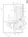
- the base 9 has two side walls 9.1 and 9.2 (see Fig.2 ) and an upper side 9.3. To any side wall, or to both side walls, guides are fastened for translating a carriage supporting the spindles and the respective tools.
- guides 21 are applied to the side wall 9.2 that extend according to a first translation direction embodied by the above-mentioned horizontal first translation axis X.
- the letter I indicates the center-to-center distance between the guides 21. The center-to-center distance is advantageously the maximum allowed by the height of the base 9, for the reasons explained below.
- a first carriage 23 is fastened, that, in the illustrated embodiment, is formed by an upright movable with respect to the base 9.
- the first carriage 23 is movable along the guides 21 according to the horizontal first translation axis X.
- the movement of the first carriage 23 along the axis X is a numerically controlled movement.
- the first carriage 23 extends vertically beyond the maximum height of the base 9.
- the first carriage 23 supports a second carriage 25 movable along a second translation axis indicated by the double arrow Y.
- the second translation axis Y is horizontal and orthogonal to the first translation axis X.
- the second carriage 25 is provided with second guides 27 that, in the embodiment of Figs. 1 to 4 , engage shoes 29 integral to the first carriage 23.
- the spindles 31, to which the tools U can be applied, are carried by the second carriage 25.
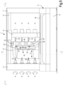
- the number of spindles 31 and the number of tools U is equal to the number of pairs of centers 13 and tailstocks 15.
- four pairs of centers and tailstocks 13, 15 and four spindles 31 are provided.
- the spindles 31 can be simultaneously driven into rotation by motors, whose number can be the same as, or different from, the number of spindles 31.
- two motors 33 are provided, each of which rotates two spindles 31.
- the tools U can perform numerically controlled movements along the axis X to machine each point of the workpieces P held between the centers 13 and the tailstocks 15.
- the numerically controlled movement along the translation axis Y allows moving the tools U towards, and away from, the side surface to be machined of the workpieces P held between the centers 13 and the tailstocks 15.
- the tools U rotate around axes parallel to the axes A, around which the workpieces P rotate.
- the structure described above is particularly stiff and is adapted to withstand high inertia loads, so that the movements along the axes X and Y can be performed at very high speed.
- the use of a first carriage 23 formed by a movable upright guided along the guides 21, whose center-to-center distance I is long allows avoiding deformations resulting from the inertial forces generated by the highly accelerated movements along the axis Y.
- the same stiffness can be achieved as regards the inertial forces according to the axis X. This allows the lathe 1 to machine the workpieces P at high speed, thanks to the opportunity of performing very significant accelerations in the directions X and Y without deformations resulting in machining errors or inaccuracies.
- a protective wall 41 is provided, preferably a flexible wall, for example a bellows-like wall.
- the wall 41 is subdivided into two portions 41A and 41B, directly or indirectly fastened to the first carriage 23, so that the two wall portions 41A, 41B define a vertical slot for the passage of the second carriage 25 and especially of the tools U, and for the movement of the tools U towards, and away from, the workpieces.
- the two wall portions 41A, 41B may have, for example, a bellows-like structure.
- flexible walls can be used, winding and unwinding around rolls with vertical axis, or even walls formed by a plurality of sectors, sliding with respect to one another, so as to lengthen and shorten telescopically.
- the flexible wall 41 separates the working area of the tools U from the area where the first carriage 23 moves. In this way it is possible, at least partially, to prevent chips from falling to the guides 21 and, partly, the guides 27.
- the chips remain in the front area of the flexible wall 41 and are collected on a conveyor 43 (schematically indicated in Fig.4 ), supported by the base 9 and preferably movable with a discharge movement parallel to the first translation axis X.
- the conveyor 43 may be housed in a cavity 9.4 ( Fig.2 ) provided on the upper side 9.3 of the base 9.
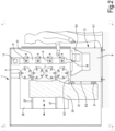
- Figs. 5 to 8 show a second embodiment of a numerically controlled multi-spindle lathe.
- the lathe 1 of Figs. 5 to 8 has a structure mostly equal to that of the lathe 1 of Figs. 1 to 4 .
- Equal or equivalent parts in the two embodiments are indicated with the same reference numbers and will not be described again.
- a third carriage 51 movable according to a third translation axis Z, orthogonal to the first translation axis X and to the second translation axis Y, i.e. a vertical axis. More exactly, the third carriage 51 is interposed between the first carriage 23 and the second carriage 25.
- the spindles 31 and the tools U can move according to three numerically controlled translation axes X, Y, Z, orthogonal to one another.
- the tools U and the spindles 31 have rotation axes parallel to the axis Y and orthogonal to the axes X and Z and orthogonal to the rotation axes A of the centers 13 and tailstocks 15 and of the workpieces P.
- the movement along Z allows the tools U to be arranged at different height with respect to the workpieces P.
Description
- The present invention relates to the field of machine tools. More in particular, the invention relates to the field of numerically controlled lathes.
- For manufacturing elongated workpieces, for example furniture components, made of wood, plastic, light alloys or the like, the use of numerically controlled lathes and copying lathes is well known. In particular, for manufacturing furniture components such as chair and table legs, multi-spindle copying lathes are known, which allow working contemporaneously a plurality of workpieces supported by a plurality of centers and tailstocks. The tools machining in parallel the plurality of workpieces are controlled through a template reproducing the shape of the product to be manufactured.
- These machines are reliable and accurate but have some drawbacks, due to the fact that they are copying machines, i.e. machines requiring the use of templates reproducing the shape of the finished product.
- It would be useful to have available a multi-spindle lathe adapted to produce, flexibly, at high productivity rates and with high accuracy, products that are currently manufactured through copying lathes.
- A numerically controlled multi-spindle lathe is known from
US 6 203 478 B1 , on which the preamble of appended claim 1 is based. - To completely or at least partially overcome the drawbacks of the prior art multi-spindle lathes, a numerically controlled multi-spindle lathe is provided with a new configuration. The lathe comprises a bearing structure with a base extending according to a first translation axis. The lathe further comprises a plurality of pairs of turning members for rotating the workpieces. Each pair comprises a center and a tailstock that are coaxial with each other and define a respective rotation axis for the workpieces. Each center is motorized and the distance between centers and tailstocks is adjustable. Motorization can be provided by a single motor with transmission members, or by a plurality of motors, each of which can rotate one or more centers. In particular, the motor, or each motor, for rotating the centers may be a numerically controlled motor, so as to impart a numerically controlled rotation to each workpiece. The configuration is preferably such as identically to machine identical workpieces supported by the pairs of centers and tailstocks. To this end, the pairs of centers and tailstocks rotate synchronously.
- Suitably, the lathe further comprises a first carriage guided on first guides that are integral with the base and extend in the direction of the first translation axis. The first carriage is advantageously provided with a numerically controlled movement along the first guides according to the first translation axis. Advantageously, the lathe further comprises a second carriage, supported by the first carriage and movable with a numerically controlled movement with respect to the first carriage. To this end, second guides are provided, extending in the direction of a second translation axis, orthogonal to the first translation axis. As it will be better explained below, the second carriage may be directly supported by the first carriage, but it is also possible to provide a further intermediate carriage between the first carriage and the second carriage, so as to have a further translation axis. The choice between one configuration and the other can be based, for example, on the number of movements that the tools shall perform with respect to the workpieces.
- The lathe also comprises a plurality of spindles with parallel axes, supported by the second carriage and adapted to rotate tools configured to work simultaneously workpieces mounted between the centers and the tailstocks. The number of spindles is typically equal to the number of pairs of centers and tailstocks. The spindles may be suitably rotate synchronously.
- In other embodiments, the number of pairs of centers and tailstocks can be twice the number of spindles, so that each tool supported by a spindle can machine two parallel workpieces simultaneously, by arranging the tool rotation axis in intermediate position between the rotation axes of the two workpieces to be machined simultaneously. In this case, machining can be performed by using spindles rotating around axes parallel to the rotation axes of the workpieces. The tools may have such a dimension (typically a diameter) so as to simultaneously machine two adjacent workpieces. In embodiments, the spindles may be provided with two translation movements according to two axes that are orthogonal to each other and to the rotation axis of the pairs of turning members for rotating the workpieces (centers and tailstocks). The first movement, orthogonal to the plane of lying of the rotation axes of the turning members for rotating the workpieces, is a numerically controlled movement towards the workpieces. The second movement, parallel to the plane of lying of the rotation axes of the turning members for rotating the workpieces, may be a numerically controlled movement, or simply an adjustment movement for aligning each of the rotation axes of the spindles with one of the rotation axes of the turning members for rotating the workpieces, or for bringing them to an intermediate position between two rotation axes of two adjacent workpieces, for simultaneously machining these two workpieces.
- The lathe structure is such as to have highly stiff guiding systems, thus allowing the carriages, in particular the second carriage, to move with high accelerations. This allows shortening the working cycles and increasing the lathe productivity. In particular, the base fixed on the ground, to which the first guides for the first carriage are fastened, allows stiffening the structure and allows high accelerations of the second carriage along the second translation axis.
- The movement along the first translation axis is typically parallel to the rotation axis of the centers and tailstocks, i.e. to the rotation axis of the workpieces. This movement is therefore parallel to the longitudinal extension of the workpieces. The movement along the second translation axis is a movement towards, and away from, the rotation axis of centers and tailstocks, i.e. orthogonal to this axis.
- In some embodiments, the second guides are integral with the second carriage and preferably comprise a pair of guides that are spaced from each other in a direction orthogonal to the first translation axis and to the second translation axis.
- In practical embodiments, the first translation axis and the second translation axis are horizontal, and the centers and the tailstocks define a plurality of rotation axes for the workpieces lying on a vertical plane, parallel to the first translation axis and orthogonal to the second translation axis.
- The term "vertical" as used herein indicates a direction parallel to the gravity direction, and the term "horizontal" indicates a direction orthogonal to the gravity direction. In the description below and the attached claims, the terms "vertical" and "horizontal" refer to the multi-spindle lathe in work position.
- In advantageous embodiments, the lathe base comprises an upper side and two side walls, extending in the direction of the first translation axis. The first guides are applied on a first side wall of the base, and the first carriage forms a movable upright adj acent to the first side wall of the base and extending vertically beyond the upper surface of the base.
- To achieve high stiffness, in some embodiments the first guides comprise a pair of guides, whose center-to-center distance is equal to at least 50% of the height of the base, and preferably to at least 70% of the height of the base. The center-to-center distance is preferably the largest possible with respect to the height of the base, taking into account any construction constraint. In this way, a significant constraint reaction is achieved, in particular a constraint reaction torque around the first translation axis, adapted to withstand high dynamic stresses generated by the accelerations of the second carriage moving along the second translation axis.
- For example, the center-to-center distance between the pair of first guides is greater than 300 mm, preferably greater than 400 mm and, more preferably, is comprised between 450 mm and 550 mm. The base height, the distance between the axes of centers and tailstocks and the number of centers and tailstocks are chosen so that an operator can load the workpieces easily.
- In some embodiments, to facilitate chips collection, the base comprises a conveyor for collecting the chips that are formed while machining the workpieces, which is arranged on the upper side of the base, for example in a lowered area of the upper side. The conveyor can move parallel to the first translation axis, but it is also possible to use a conveyor, whose width extends parallel to the first translation axis and which moves in the direction of the second translation axis.
- In embodiments described herein, the tailstocks are supported by an upright movable parallel to the first translation axis, to adjust the distance between the centers and the tailstocks. The centers are supported by an upright that is fixed with respect to the base. In this way, a simpler configuration is provided, as the motors of the centers are supported by the fixed upright. A reverse arrangement is also possible.
- The movable upright supporting the tailstocks may be advantageously guided on lower guides integral with the base and parallel to the first guides, and, if necessary, on upper guides supported by the bearing structure above the base.
- In advantageous embodiments, the lathe can comprise a flexible protective wall, approximately parallel to the first translation axis and approximately orthogonal to the second translation axis. The wall separates a machining area, where the centers and the tailstocks, as well as the chips collecting conveyor, if any, are arranged, from a protected back area, where the first carriage and the respective first guides are arranged. The second carriage may extend through the flexible wall to bring the tools into working position.
- In some embodiments, the lathe comprises a third carriage, interposed between the first carriage and the second carriage. The second carriage is supported by the third carriage and is movable with respect to the third carriage along the second translation axis. The third carriage is supported by the first carriage and is movable along a third translation axis with a numerically controlled translation movement. The third translation axis is preferably orthogonal to the first translation axis and to the second translation axis. If the first two translation axes are horizontal, the third translation axis is vertical.
- Further features and advantageous embodiments are described below and defined in the attached claims.
- The invention shall be better understood by following the description and the accompanying drawing, which show non-limiting examples of embodiment of the invention. More specifically, in the drawing:
-
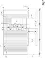
Fig.1 is a front view according to I-I ofFig.2 of a first embodiment of a multi-spindle lathe; -
Fig.2 is a cross-section according to II-II ofFig. 1 ; -
Fig.3 is a rear view according to III-III ofFig.2 ; -
Fig.4 is a plan view according to IV-IV ofFig. 1 ; -
Fig.5 is a front view according to V-V ofFig.6 of a second embodiment of a multi-spindle lathe; -
Fig.6 is a cross-section according to VI-VI ofFig.5 ; -
Fig.7 is a rear view according to VII-VII ofFig.6 ; and -
Fig.8 is a plan view according to VIII-VIII ofFig.5 . - A first embodiment of a multi-spindle lathe is shown in
Figs. 1-4 . The lathe is indicated with number 1 and comprises abearing structure 3. The bearingstructure 3 comprises a firstvertical upright 5 and a secondvertical upright 7, rigidly connected to a lowerhorizontal base 9. Theuprights horizontal crossbar 11. - A plurality of
centers 13 are supported by theupright 5. Each center is associated with atailstock 15. Each center is coaxial with the respective tailstock. The letter A indicates the rotation axes of the pairs of centers and tailstocks, which define members supporting and rotating the workpieces P to be machined. Eachcenter 13 is driven into rotation around the respective axis A by a numerically controlled motor, not shown. Preferably, the motors of thecenters 13 are so controlled that all centers 13 rotate synchronously. In this way, a plurality of tools U (Fig.2 ) supported by spindles 31 (described in more detail below) can machine synchronously and simultaneously all workpieces P supported and rotated by the pairs of centers andtailstocks spindles 31 supporting them, rotate around axes parallel to the rotation axes A of thecenters 13 and thetailstocks 15, i.e. horizontal axes parallel to a first numerically controlled translation axis X, along which the tools U move, and orthogonal to a second numerically controlled translation axis Y, along which the tools U move, that are described in greater detail below. The configuration and arrangement of thespindles 31 and of the respective tools U, and of thecenters 13 andtailstocks 15, are such that the workpieces P are machined as mentioned above (rotation axes of the tools U parallel to the rotation axes A of thecenters 13 and thetailstocks 15, and therefore to the rotation axes of the workpieces P being machined). In other words, this arrangement is such that the workpieces and the tools co-act while the axes A are parallel to the rotation axes of the tools U and of thespindles 31 carrying them. - The
tailstocks 15 are supported by a bearing structure allowing the movement thereof in a direction parallel to the translation axis X to adjust the distance betweencenters 13 andtailstocks 15. In this embodiment, the bearing structure comprises amovable upright 17 extending vertically. Themovable upright 17 can be guided along adjustment upper guides carried by thecrossbar 11 and by adjustmentlower guides 19, which can be preferably integral with thebase 9 and extending in the same direction of thebase 9, i.e. parallel to the axis X. In this way it is possible to adapt the distance between allcenters 13 and therespective tailstocks 15 to the length of the workpieces P. - The
base 9 has two side walls 9.1 and 9.2 (seeFig.2 ) and an upper side 9.3. To any side wall, or to both side walls, guides are fastened for translating a carriage supporting the spindles and the respective tools. In the illustrated embodiment, guides 21 are applied to the side wall 9.2 that extend according to a first translation direction embodied by the above-mentioned horizontal first translation axis X. The letter I indicates the center-to-center distance between theguides 21. The center-to-center distance is advantageously the maximum allowed by the height of thebase 9, for the reasons explained below. - To the guides 21 a
first carriage 23 is fastened, that, in the illustrated embodiment, is formed by an upright movable with respect to thebase 9. Thefirst carriage 23 is movable along theguides 21 according to the horizontal first translation axis X. The movement of thefirst carriage 23 along the axis X is a numerically controlled movement. - The
first carriage 23 extends vertically beyond the maximum height of thebase 9. Thefirst carriage 23 supports asecond carriage 25 movable along a second translation axis indicated by the double arrow Y. The second translation axis Y is horizontal and orthogonal to the first translation axis X. To allow the movement along the second translation axis Y, thesecond carriage 25 is provided withsecond guides 27 that, in the embodiment ofFigs. 1 to 4 , engageshoes 29 integral to thefirst carriage 23. - The
spindles 31, to which the tools U can be applied, are carried by thesecond carriage 25. In the embodiment ofFigs. 1 to 4 , the number ofspindles 31 and the number of tools U is equal to the number of pairs ofcenters 13 andtailstocks 15. In the illustrated example, four pairs of centers andtailstocks spindles 31 are provided. Thespindles 31 can be simultaneously driven into rotation by motors, whose number can be the same as, or different from, the number ofspindles 31. In the illustrated example, twomotors 33 are provided, each of which rotates twospindles 31. - Thanks to the movements along the translation axes X and Y described above, the tools U can perform numerically controlled movements along the axis X to machine each point of the workpieces P held between the
centers 13 and thetailstocks 15. The numerically controlled movement along the translation axis Y allows moving the tools U towards, and away from, the side surface to be machined of the workpieces P held between thecenters 13 and thetailstocks 15. - As mentioned above, during machining, i.e. when the tools U are touching the workpieces P, the tools U rotate around axes parallel to the axes A, around which the workpieces P rotate.
- The structure described above is particularly stiff and is adapted to withstand high inertia loads, so that the movements along the axes X and Y can be performed at very high speed. In particular, the use of a
first carriage 23 formed by a movable upright guided along theguides 21, whose center-to-center distance I is long, allows avoiding deformations resulting from the inertial forces generated by the highly accelerated movements along the axis Y. The same stiffness can be achieved as regards the inertial forces according to the axis X. This allows the lathe 1 to machine the workpieces P at high speed, thanks to the opportunity of performing very significant accelerations in the directions X and Y without deformations resulting in machining errors or inaccuracies. - According to advantageous embodiments, in order that the numerically controlled multi-spindle lathe 1 works smoothly and efficiently, a
protective wall 41 is provided, preferably a flexible wall, for example a bellows-like wall. Thewall 41 is subdivided into twoportions first carriage 23, so that the twowall portions second carriage 25 and especially of the tools U, and for the movement of the tools U towards, and away from, the workpieces. The twowall portions - The
flexible wall 41 separates the working area of the tools U from the area where thefirst carriage 23 moves. In this way it is possible, at least partially, to prevent chips from falling to theguides 21 and, partly, theguides 27. The chips remain in the front area of theflexible wall 41 and are collected on a conveyor 43 (schematically indicated inFig.4 ), supported by thebase 9 and preferably movable with a discharge movement parallel to the first translation axis X. As shown inFig.4 , theconveyor 43 may be housed in a cavity 9.4 (Fig.2 ) provided on the upper side 9.3 of thebase 9. -
Figs. 5 to 8 show a second embodiment of a numerically controlled multi-spindle lathe. The lathe 1 ofFigs. 5 to 8 has a structure mostly equal to that of the lathe 1 ofFigs. 1 to 4 . Equal or equivalent parts in the two embodiments are indicated with the same reference numbers and will not be described again. - The main difference between the embodiment of
Figs. 1 to 4 and the embodiment ofFigs. 5 to 8 is the presence of athird carriage 51, movable according to a third translation axis Z, orthogonal to the first translation axis X and to the second translation axis Y, i.e. a vertical axis. More exactly, thethird carriage 51 is interposed between thefirst carriage 23 and thesecond carriage 25. Thesecond carriage 25, instead of being directly fastened, through theguides 27, to thefirst carriage 23, is fastened through theguides 27 to thethird carriage 51. This latter is in turn fastened, throughguides 53, to thefirst carriage 21, so as to move with a numerically controlled movement along the vertical third translation axis Z. - In this way, the
spindles 31 and the tools U can move according to three numerically controlled translation axes X, Y, Z, orthogonal to one another. - Furthermore, in the embodiment of
Figs. 5 to 8 the tools U and thespindles 31 have rotation axes parallel to the axis Y and orthogonal to the axes X and Z and orthogonal to the rotation axes A of thecenters 13 andtailstocks 15 and of the workpieces P. The movement along Z allows the tools U to be arranged at different height with respect to the workpieces P.
Claims (15)
- A numerically controlled multi-spindle lathe (1) comprising:a bearing structure (3) with a base (9) extending according to a first translation axis (X); wherein the base (9) comprises an upper side (9.3) and two side walls (9.1, 9.2), extending in the direction of the first translation axis (X);a plurality of pairs of turning members (13, 15) for rotating workpieces (P), each pair comprising a center (13) and a tailstock (15) that are coaxial with each other and define a respective rotation axis (A) of the workpieces (P); wherein each center (13) is motorized; and wherein the distance between the centers and the tailstocks is adjustable;a first carriage (23) guided on first guides (21) integral with the base (9) and extending in the direction of the first translation axis (X); wherein the first carriage (23) is provided with a numerically controlled movement along the first translation axis (X);a second carriage (25), supported by the first carriage (23) and movable with a numerically controlled movement with respect to the first carriage (23), on second guides (27), in the direction of a second translation axis (Y), orthogonal to the first translation axis (X); anda plurality of spindles (31) with parallel axes, carried by the second carriage (25) and adapted to rotate tools (U) configured to work simultaneously workpieces mounted between the centers (13) and the tailstocks (15);characterised in thatthe first guides (21) are applied to at least one first side wall of the base and the first carriage is adjacent to said first wall and extends vertically beyond the upper surface of the base (9).
- The lathe (1) of claim 1, wherein the base (9) comprises a conveyor (43) for collecting the chips that are formed while machining the workpieces (P), which is arranged on the upper side (9.3) of the base (9) and is preferably housed in a cavity (9.4) provided on the upper side (9.3) of the base (9).
- The lathe (1) of claim 1 or 2, wherein the centers (13) are provided with motorization members controlling the synchronous rotation of the centers in concordant or discordant directions.
- The lathe (1) of one of the previous claims, wherein the second guides (27) are integral with the second carriage (25) and preferably comprise a pair of guides that are spaced from each other in a direction orthogonal to the first translation axis (X) and to the second translation axis (Y).
- The lathe (1) of one of the previous claims, wherein the first translation axis (X) and the second translation axis (Y) are horizontal, and wherein the centers (13) and the tailstocks (15) define a plurality of rotation axes (A) for the workpieces (P) lying on a vertical plane parallel to the first translation axis (X) and orthogonal to the second translation axis (Y).
- The lathe (1) of one of the previous claims, wherein the first carriage (23) forms a movable upright adjacent to the first side wall (9.2) of the base (9) and movable along said wall.
- The lathe (1) of claim 6, wherein the first guides (21) comprise a pair of guides, whose center-to-center distance is equal to at least 50% of the height of the base (9), and preferably to at least 70% of the height of the base (9).
- The lathe (1) of claim 6, wherein the center-to-center distance (I) between the pair of first guides (21) is greater than 300 mm, preferably greater than 400 mm and, more preferably, is comprised between 450 mm and 550 mm.
- The lathe (1) of one of the previous claims, wherein the tailstocks (15) are supported by an upright (17) that is movable parallel to the first translation axis (X) to adjust the distance between the centers (13) and the tailstocks (15), and wherein the centers (13) are supported by an upright (5) that is fixed with respect to the base (9), or vice versa; and wherein motors for rotating the centers (13) are preferably supported by the fixed upright (5).
- The lathe (1) of claim 9, wherein the movable upright (17) supporting the tailstocks (15) is guided on lower guides (19) preferably integral with the base (9) and parallel to the first guides (21) along which the first carriage (23) moves, and on upper guides (11) carried by the bearing structure (3) above the base (9).
- The lathe (1) of one of the previous claims, comprising a protective wall (41), preferably flexible and preferably having a bellows-like structure, approximately parallel to the first translation axis (X) and approximately orthogonal to the second translation axis (Y), which separates a machining area, where the centers (13) and the tailstocks (15) are arranged, from a protected back area, where the first carriage (23) is arranged; wherein preferably the second carriage (25) extends through the flexible wall (41).
- The lathe (1) of claim 11, wherein the protective wall (41) comprises a first wall portion (41A) and a second wall portion (41B), between which a passage for the tools (U) is formed, the first wall portion (41A) and the second wall portion (41B) being fastened to the first carriage (23) to allow lengthening and shortening of one of said first wall portion and second wall portion and contemporaneously shortening and lengthening the other of said first wall portion and second wall portion, when the first carriage (23) translates along the first translation axis (X).
- The lathe (1) of one of the previous claims, wherein the spindles (31) and the centers (13) and tailstocks (15) are so configured and arranged that the workpieces (P) are machined with the rotation axes of the tools (U) and of the spindles (31) parallel to the rotation axes (A) of the centers (13) and the tailstocks (15).
- The lathe (1) of one of claims 1 to 13, wherein the spindles (31) comprise rotation axes that are parallel to the second translation axis (Y).
- The lathe (1) of one of the previous claims, comprising a third carriage (51), interposed between the first carriage (23) and the second carriage (25); wherein the second carriage (25) is supported by the third carriage (51) and is movable with respect to the third carriage (51) along the second translation axis (Y); and wherein the third carriage (51) is supported by the first carriage (23) and is movable along a third translation axis (Z) with a numerically controlled translation movement, the third translation axis (Z) being orthogonal to the first translation axis (X) and to the second translation axis (Y).
Priority Applications (1)
| Application Number | Priority Date | Filing Date | Title |
|---|---|---|---|
| EP23209404.5A EP4316702A3 (en) | 2020-01-30 | 2021-01-22 | Numerically controlled multi-spindle lathe |
Applications Claiming Priority (1)
| Application Number | Priority Date | Filing Date | Title |
|---|---|---|---|
| IT102020000001789A IT202000001789A1 (en) | 2020-01-30 | 2020-01-30 | A NUMERICALLY CONTROLLED MULTI-SPINDLE LATHE |
Related Child Applications (2)
| Application Number | Title | Priority Date | Filing Date |
|---|---|---|---|
| EP23209404.5A Division-Into EP4316702A3 (en) | 2020-01-30 | 2021-01-22 | Numerically controlled multi-spindle lathe |
| EP23209404.5A Division EP4316702A3 (en) | 2020-01-30 | 2021-01-22 | Numerically controlled multi-spindle lathe |
Publications (2)
| Publication Number | Publication Date |
|---|---|
| EP3858542A1 EP3858542A1 (en) | 2021-08-04 |
| EP3858542B1 true EP3858542B1 (en) | 2024-03-06 |
Family
ID=70295948
Family Applications (2)
| Application Number | Title | Priority Date | Filing Date |
|---|---|---|---|
| EP23209404.5A Pending EP4316702A3 (en) | 2020-01-30 | 2021-01-22 | Numerically controlled multi-spindle lathe |
| EP21153064.7A Active EP3858542B1 (en) | 2020-01-30 | 2021-01-22 | Numerically controlled multi-spindle lathe |
Family Applications Before (1)
| Application Number | Title | Priority Date | Filing Date |
|---|---|---|---|
| EP23209404.5A Pending EP4316702A3 (en) | 2020-01-30 | 2021-01-22 | Numerically controlled multi-spindle lathe |
Country Status (2)
| Country | Link |
|---|---|
| EP (2) | EP4316702A3 (en) |
| IT (1) | IT202000001789A1 (en) |
Families Citing this family (1)
| Publication number | Priority date | Publication date | Assignee | Title |
|---|---|---|---|---|
| EP4309833A1 (en) | 2022-07-21 | 2024-01-24 | Paolino Bacci S.R.L. | A double multi-spindle lathe |
Family Cites Families (6)
| Publication number | Priority date | Publication date | Assignee | Title |
|---|---|---|---|---|
| JPS53115489U (en) * | 1977-02-22 | 1978-09-13 | ||
| FR2530991A1 (en) * | 1982-07-27 | 1984-02-03 | Mavilor | HIGH-PERFORMANCE AUTOMATIC MACHINING MACHINE USING A CYCLIC PROCESS OF MACHINING AND COMBINED TRANSLATION OPERATIONS |
| ES2167146B1 (en) * | 1999-04-19 | 2003-11-01 | Etxetar Sa | MACHINE TO DRILL HOLES OF OILS IN CRANKSHAIRS AND CORRESPONDING PROCEDURE. |
| DE502008003436D1 (en) * | 2008-09-09 | 2011-06-16 | Wyssbrod Technologie Ag | milling Machine |
| CA2852206C (en) * | 2013-05-24 | 2020-07-21 | Ernesto Cano | Machine for machining crankshafts |
| EP3434412B1 (en) * | 2017-07-27 | 2022-12-21 | GF Machining Solutions AG | Machine tool |
-
2020
- 2020-01-30 IT IT102020000001789A patent/IT202000001789A1/en unknown
-
2021
- 2021-01-22 EP EP23209404.5A patent/EP4316702A3/en active Pending
- 2021-01-22 EP EP21153064.7A patent/EP3858542B1/en active Active
Also Published As
| Publication number | Publication date |
|---|---|
| IT202000001789A1 (en) | 2021-07-30 |
| EP3858542A1 (en) | 2021-08-04 |
| EP4316702A3 (en) | 2024-04-10 |
| EP4316702A2 (en) | 2024-02-07 |
Similar Documents
| Publication | Publication Date | Title |
|---|---|---|
| JP3068001B2 (en) | Machine tools with multiple spindles | |
| CN102161159B (en) | Vertical-horizontal combined machining centre | |
| US20110233879A1 (en) | Carrier device for machine tools | |
| CN201970090U (en) | Vertical-horizontal combined machining center | |
| CN109262288A (en) | Double main shaft double-workbench horizontal Machining centers | |
| CN201079837Y (en) | Sizing frame hole type turning device | |
| CN110636920B (en) | Machine tool with two working spindles | |
| CN111002047A (en) | Numerical control movable beam type five-axis gantry machining center machine tool | |
| US20150043984A1 (en) | Machine tool and method for the machining of workpieces having at least two separate machining units | |
| US7124666B2 (en) | Multiple spindle machine tool | |
| CN109318060A (en) | A kind of double main shaft double-workbench horizontal Machining centers of fixed column type | |
| US4704773A (en) | Machine tool structure | |
| EP3858542B1 (en) | Numerically controlled multi-spindle lathe | |
| CN210877739U (en) | Vertical and horizontal combined machining center | |
| US7008152B2 (en) | Machine tool for processing work pieces on at least three axes | |
| JP2014065133A (en) | Parallel two-axis composite machine tool | |
| EP1247611B1 (en) | A multi-axis work centre, for multiple production, in particular for wood working | |
| CN212217764U (en) | Numerical control movable beam type five-axis gantry machining center machine tool | |
| CN209157698U (en) | Double main shaft double-workbench horizontal Machining centers | |
| US6484611B1 (en) | Lathe | |
| KR101801202B1 (en) | Machining center with multiple spindle | |
| EP1974853A1 (en) | Apparatus for machining workpieces | |
| CN115816105A (en) | Five-axis milling machining center | |
| CN110340412B (en) | Vertical and horizontal combined machining center | |
| CN211804217U (en) | Composite processing numerical control machine tool for processing worm by generating method |
Legal Events
| Date | Code | Title | Description |
|---|---|---|---|
| PUAI | Public reference made under article 153(3) epc to a published international application that has entered the european phase |
Free format text: ORIGINAL CODE: 0009012 |
|
| STAA | Information on the status of an ep patent application or granted ep patent |
Free format text: STATUS: THE APPLICATION HAS BEEN PUBLISHED |
|
| AK | Designated contracting states |
Kind code of ref document: A1 Designated state(s): AL AT BE BG CH CY CZ DE DK EE ES FI FR GB GR HR HU IE IS IT LI LT LU LV MC MK MT NL NO PL PT RO RS SE SI SK SM TR |
|
| STAA | Information on the status of an ep patent application or granted ep patent |
Free format text: STATUS: REQUEST FOR EXAMINATION WAS MADE |
|
| 17P | Request for examination filed |
Effective date: 20211028 |
|
| RBV | Designated contracting states (corrected) |
Designated state(s): AL AT BE BG CH CY CZ DE DK EE ES FI FR GB GR HR HU IE IS IT LI LT LU LV MC MK MT NL NO PL PT RO RS SE SI SK SM TR |
|
| GRAP | Despatch of communication of intention to grant a patent |
Free format text: ORIGINAL CODE: EPIDOSNIGR1 |
|
| STAA | Information on the status of an ep patent application or granted ep patent |
Free format text: STATUS: GRANT OF PATENT IS INTENDED |
|
| INTG | Intention to grant announced |
Effective date: 20230719 |
|
| GRAS | Grant fee paid |
Free format text: ORIGINAL CODE: EPIDOSNIGR3 |
|
| GRAA | (expected) grant |
Free format text: ORIGINAL CODE: 0009210 |
|
| STAA | Information on the status of an ep patent application or granted ep patent |
Free format text: STATUS: THE PATENT HAS BEEN GRANTED |
|
| AK | Designated contracting states |
Kind code of ref document: B1 Designated state(s): AL AT BE BG CH CY CZ DE DK EE ES FI FR GB GR HR HU IE IS IT LI LT LU LV MC MK MT NL NO PL PT RO RS SE SI SK SM TR |
|
| REG | Reference to a national code |
Ref country code: CH Ref legal event code: EP |
|
| REG | Reference to a national code |
Ref country code: DE Ref legal event code: R096 Ref document number: 602021009957 Country of ref document: DE |
|
| REG | Reference to a national code |
Ref country code: IE Ref legal event code: FG4D |