EP0458001B1 - Verbesserung an Kehlenmaschinen für die Holzbearbeitung - Google Patents
Verbesserung an Kehlenmaschinen für die Holzbearbeitung Download PDFInfo
- Publication number
- EP0458001B1 EP0458001B1 EP90830617A EP90830617A EP0458001B1 EP 0458001 B1 EP0458001 B1 EP 0458001B1 EP 90830617 A EP90830617 A EP 90830617A EP 90830617 A EP90830617 A EP 90830617A EP 0458001 B1 EP0458001 B1 EP 0458001B1
- Authority
- EP
- European Patent Office
- Prior art keywords
- tool
- hold
- hood
- horizontal
- work
- Prior art date
- Legal status (The legal status is an assumption and is not a legal conclusion. Google has not performed a legal analysis and makes no representation as to the accuracy of the status listed.)
- Expired - Lifetime
Links
- 238000000465 moulding Methods 0.000 title claims description 7
- 238000003754 machining Methods 0.000 description 4
- 229910000831 Steel Inorganic materials 0.000 description 2
- 239000010959 steel Substances 0.000 description 2
- 230000007547 defect Effects 0.000 description 1
- 230000001419 dependent effect Effects 0.000 description 1
- 239000000428 dust Substances 0.000 description 1
- 230000000694 effects Effects 0.000 description 1
- 230000002708 enhancing effect Effects 0.000 description 1
- 238000000605 extraction Methods 0.000 description 1
- 238000000034 method Methods 0.000 description 1
- 230000001681 protective effect Effects 0.000 description 1
Images

Classifications
-
- B—PERFORMING OPERATIONS; TRANSPORTING
- B27—WORKING OR PRESERVING WOOD OR SIMILAR MATERIAL; NAILING OR STAPLING MACHINES IN GENERAL
- B27C—PLANING, DRILLING, MILLING, TURNING OR UNIVERSAL MACHINES FOR WOOD OR SIMILAR MATERIAL
- B27C5/00—Machines designed for producing special profiles or shaped work, e.g. by rotary cutters; Equipment therefor
- B27C5/02—Machines with table
- B27C5/06—Arrangements for clamping or feeding work
-
- B—PERFORMING OPERATIONS; TRANSPORTING
- B23—MACHINE TOOLS; METAL-WORKING NOT OTHERWISE PROVIDED FOR
- B23Q—DETAILS, COMPONENTS, OR ACCESSORIES FOR MACHINE TOOLS, e.g. ARRANGEMENTS FOR COPYING OR CONTROLLING; MACHINE TOOLS IN GENERAL CHARACTERISED BY THE CONSTRUCTION OF PARTICULAR DETAILS OR COMPONENTS; COMBINATIONS OR ASSOCIATIONS OF METAL-WORKING MACHINES, NOT DIRECTED TO A PARTICULAR RESULT
- B23Q3/00—Devices holding, supporting, or positioning work or tools, of a kind normally removable from the machine
- B23Q3/002—Means to press a workpiece against a guide
-
- B—PERFORMING OPERATIONS; TRANSPORTING
- B27—WORKING OR PRESERVING WOOD OR SIMILAR MATERIAL; NAILING OR STAPLING MACHINES IN GENERAL
- B27C—PLANING, DRILLING, MILLING, TURNING OR UNIVERSAL MACHINES FOR WOOD OR SIMILAR MATERIAL
- B27C1/00—Machines for producing flat surfaces, e.g. by rotary cutters; Equipment therefor
- B27C1/08—Machines for working several sides of work simultaneously
-
- B—PERFORMING OPERATIONS; TRANSPORTING
- B27—WORKING OR PRESERVING WOOD OR SIMILAR MATERIAL; NAILING OR STAPLING MACHINES IN GENERAL
- B27C—PLANING, DRILLING, MILLING, TURNING OR UNIVERSAL MACHINES FOR WOOD OR SIMILAR MATERIAL
- B27C1/00—Machines for producing flat surfaces, e.g. by rotary cutters; Equipment therefor
- B27C1/12—Arrangements for feeding work
-
- B—PERFORMING OPERATIONS; TRANSPORTING
- B27—WORKING OR PRESERVING WOOD OR SIMILAR MATERIAL; NAILING OR STAPLING MACHINES IN GENERAL
- B27G—ACCESSORY MACHINES OR APPARATUS FOR WORKING WOOD OR SIMILAR MATERIALS; TOOLS FOR WORKING WOOD OR SIMILAR MATERIALS; SAFETY DEVICES FOR WOOD WORKING MACHINES OR TOOLS
- B27G19/00—Safety guards or devices specially adapted for wood saws; Auxiliary devices facilitating proper operation of wood saws
- B27G19/10—Measures preventing splintering of sawn portions of wood
Definitions
- the present invention relates to an improvement in moulding machines for woodworking.
- Some solutions are known which refer to planning machines, such as thickness planners, in which is desirable yieldingly to hold the stock down against the bed or table as it is fed through the machine.
- An example is the pubblication US-A-2,780,254 in which the cutter head is provided by a cutter tool which is bilaterally supported by the front and rear walls of the cutter head which is vertically slidable along vertically disposed posts; to hold the stock against the bed are also provided front and rear rollers which are pivotally mounted on the side walls of the head and are vertically movable with the tool and the cutter head: this does not permit an easy regulation of the hold rollers in the event of the diameter tool changing.
- the work is fed by wheels (rubber faced, or steel) positoned between the tools and rotating about shafts parallel with the bed, which are supported by and driven together from a back rail in such a way that pieces are directed continuously along the feed path and into engagement with the tools.
- wheels rubber faced, or steel
- the four tool heads designated each to a relative face of the work (taken along the feed direction, right side, left side, top and bottom respectively) are accommodated internally of protective and dust extraction casings and provided with two elements, disposed one on either side and located externally of the casing, by which the work is held down going into, through and beyond the cutting stroke; more exactly, the first hold-down element encountered is angled in order to direct the work onto the tool, whereas the second is positioned parallel to the bed and distanced therefrom at a height that will depend on the prescribed thickness of the machined work.
- the operation of replacing any one of the tools is lengthy and laborious.
- the operator initially must detach the two hold-down elements, separating them from the supporting back rail, before the single tool can be removed; the replacement tool must then be aligned with the bed (according to the new diameter), using handwheels and graduated scales afforded by the machine, by means of which the operator can check and adjust the distance (height) of the axis of rotation of the tool from the bed.
- the two hold-down elements must be repositioned to suit the diameter of the new tool (the plane occupied by the hold-down elements coincides with the cutting edge at the smallest diameter of the tool), and its distance from the bed (equivalent to the thickness of the work).
- a further drawback affecting through feed moulders is occasioned by the considerable distance between centres of the feed wheel positioned immediately preceding the horizontal tools, and the first wheel encountered thereafter. This clearly represents a source of difficulty when the work to be machined is of length less than the distance in question, as the workpiece will tend to stand still (for want of driving contact) as soon as it is past the first of the two horizontal tools, remaining unable to reach the wheel next after the second horizontal tool until jogged forward by a further workpiece.
- the object of the present invention is to overcome the drawbacks in question by reordering a moulding machine in such a way as to optimize tool change operations, and at the same time to ensure uninterrupted progress of the work along the entire length of the feed path.
- the stated object is realized in an improvement as characterized in the appended claims, whereby the hood covering one of the horizontal moulding tools serves also to support the two relative hold-down guides, one connected rigidly on either side, and means are incorporated, operating between the hood and the slide, by which to adjust the distance of the hood from the horizontal bed in keeping with a reference diameter assigned to the tool; also, the second of the two hold-down guides encountered by the work affords a recess in which to accommodate a feed wheel mounted to the back rail of the machine.
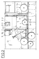
- the improvement in moulding machines for woodworking relates to through feed moulders of the type comprising a set of spindle heads installed in-line along a horizontal bed 1 and affording a plurality of tools 2, 3, 4 and 5 (see fig 1) by which the four faces of a workpiece 6 are machined.
- the four tools are designated right hand vertical, left hand vertical, top horizontal and bottom horizontal respectively, indicating the face of the work 6 machined by the individual tool.
- fig 1 Also illustrated in fig 1 are two further tools installed respectively at the start and finish of the moulding cycle, which may contribute to the machining operation according to the format of the work 6; in the case in point, these are a planer 21 (located at the entry end, in relation to the feed direction F) and a universal cutter 22 installed at the exit end and serving to shape angled surfaces.
- a planer 21 located at the entry end, in relation to the feed direction F
- a universal cutter 22 installed at the exit end and serving to shape angled surfaces.
- Each tool 2, 3, 4 and 5 is mounted to a respective slide 7 of which the position in relation to the machine will depend on the individual type of tool; these slides 7 (one only is illustrated in fig 1) serve to vary the operating clearance of the tool in relation to a given datum 1 or work face, which happens to coincide with the horizontal bed in the case of the tool shown in fig 1 by way of example.
- hold-down elements 9 and 10 are also associated with each of the four tools 2, 3, 4 and 5, positioned preceding and following in close proximity to each side of the relative tool hood 8, positioned preceding and following in close proximity to each side of the relative tool hood 8, and hold-down elements 9 and 10 consisting in a pair of guides of which the first 9 encountered by the work 6 is angled in relation to the bed 1 and the second 10 disposed parallel thereto, in such a way as to direct and steady the work, respectively, during the cutting stroke.
- Fig 1 also illustrates roller means 11 consisting in a plurality of steel or rubber faced wheels 15 occupying the entire length of the horizontal bed 1 and mounted to a back rail 12 which flanks the bed at the rear, as viewed in the drawings; these same wheels 15 provide the means by which the work 6 is fed from one tool to the next, and are rotatable about respective axes disposed transversely to the longitudinal axis of the horizontal bed 1.
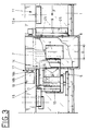
- the improvement disclosed consists principally in providing each tool 2, 3, 4 and 5 with a relative hood 8 and associating the two hold-down guides 9 and 10 rigidly with the hood, one on either side, by means of relative screw fasteners 24 and 25.
- the hood 8 is equipped further with adjustment means denoted 13, operating between the hood itself and the slide 7, by which the position of the hood can be varied in relation to the horizontal bed 1 commensurately with a reference diameter D assigned to the tool; this diameter will be determined at each change using the nominal diameter of the tool
- the adjustment means 13 operating between the hood 8 and the slide 7 consist in a lead screw mechanism 40 of conventional embodiment (illustrated schematically in phantom line), and a handwheel 40a mounted to the exterior of the hood 8 giving simple and sure operation; such a mechanism will be connected in turn to respective indication means, which in a simple embodiment can take the form of a graduated scale preferably in conjunction with a display 26 showing the value of the tool reference diameter D.
- the second hold-down guide 10 affords a housing 14 shaped distinctly as an outward facing recess 16 sunk into the face directed toward the back rail 12, the wheel 15 being keyed to the rail and accommodated partly within the recess 16.
- Such means 17 consist in conventional cam elements which allow the wheel 15 to adapt to the position assumed by the second hold-down guide 10 within a prescribed range of movement. With this expedient moreover, the height of the hood 8 can be adjusted without occasioning any interference between the second hold-down guide 10 (rigidly associated with the hood) and the feed wheel 15.
Landscapes
- Life Sciences & Earth Sciences (AREA)
- Engineering & Computer Science (AREA)
- Mechanical Engineering (AREA)
- Wood Science & Technology (AREA)
- Forests & Forestry (AREA)
- Milling, Drilling, And Turning Of Wood (AREA)
- Chemical And Physical Treatments For Wood And The Like (AREA)
Claims (4)
- Verbesserung an Kehlmaschinen für die Holzbearbeitung vom Typ enthaltend eine Gruppe von Spindelköpfen, angeordnet dicht an einem horizontalen Bett (1) und dazu bestimmt, vier Flächen eines Werkstuckes (6) mit einer Anzahl von Werkzeugen (2, 3, 4, 5) zu bearbeiten, von denen jedes an einem jeweiligen Schlitten (7) montiert ist, durch welchen die Position der Schneidkante vertikal eingestellt werden kann, und zwar in einer Richtung normal zu der Bearbeitungsfläche, wobei jedes Werkzeug (2, 3, 4, 5) im Inneren einer entsprechenden Haube (8) angeordnet ist, vor und hinter der sich erste und zweite Halteführungen (9, 10) befinden, die jeweils dazu dienen, das Werkstück (6) entlang der Bearbeitungsstrecke zu leiten und zu stabilisieren, und das Werkstuck wird dabei von dem einen Werkzeug zum nächsten durch eine Anzahl von Zuführrollenmitteln (11) zugeführt, welche über die gesamte Länge des horizontalen Bettes (1) reichen und von einer Schiene (12) getragen werden, welche hinten an dem Bett angeordnet und im Verhältnis zu dem horizontalen Bett (1) senkrecht beweglich ist, dadurch gekennzeichnet,- dass die Halteführungen (9, 10), die sich auf wenigstens ein horizontales Werkzeug (4, 5) beziehen, starr an die Seiten der jeweiligen Haube (8) angeschlossen sind und diese im Verhältnis zu dem entsprechenden Trägerschlitten (7) vertikal verstellbar ist;- dass zwischen der Haube (8) und dem Werkzeugschlitten (7) Mittel (13) enthalten sind, um die genannte Haube im Verhältnis zu dem genannten Schlitten (7) zu bewegen und den Abstand zwischen der Haube und dem Werkstück einzustellen, und zwar entsprechend zu einem Bezugsdurchmesser (D), welcher dem Werkzeug zugeordnet ist; und- dass die zweite Halteführung (10) einen Sitz (14) aufweist, wobei eins der genannten Anzahl von Rollenmitteln (11), die an der Schiene (12) montiert sind, wenigstens zu einem Teil in dem genannten Sitz (14) aufgenommen wird.
- Verbesserung nach Patentanspruch 1, enthaltend Rollenmittel (11), die aus einer Anzahl von Zuführrädern (15) bestehen, von denen jedes um eine quer im Verhältnis zu der Längsachse des horizontalen Bettes (1) angeordnete Achse drehbar ist, dadurch gekennzeichnet, dass der von der zweiten Halteführung (10) aufgewiesene Sitz (14) als eine frontal nach aussen gerichtete Ausbuchtung (16) erscheint, die der Schiene (12) zugewandt und so angeordnet ist, dass sie mit dein Teil der Schiene übereinstimmt, an welchem das aufgenommene Rad (15) aufgekeilt ist.
- Verbesserung nach Patentanspruch 1, enthaltend weiterhin Nockenmittel (17), die der Seite der Haube (8) zugeordnet sind und mit einer Steuervorrichtung (18) zusammenwirken, die sich an der rückwärtigen Trägerschiene (12) befindet, und durch welche die Rollenmittel (11) in die Lage versetzt werden, der Bewegung der zweiten Halteführung (10) innerhalb eines bestimmten Bereiches von Positionswerten zu folgen.
- Verbesserung nach Patentanspruch 1, dadurch gekennzeichnet, dass die zweite, den Sitz (14) aufweisende Halteführung (10) fest mit dem horizontalen Werkzeug (4) verbunden ist, angeordnet zur Bearbeitung der oberen horizontalen Fläche des Werkstückes (6).
Applications Claiming Priority (2)
| Application Number | Priority Date | Filing Date | Title |
|---|---|---|---|
| IT351990 | 1990-05-24 | ||
| IT3519A IT1238926B (it) | 1990-05-24 | 1990-05-24 | Perfezionamento in macchine scorniciatrici per la lavorazione del legno |
Publications (3)
| Publication Number | Publication Date |
|---|---|
| EP0458001A2 EP0458001A2 (de) | 1991-11-27 |
| EP0458001A3 EP0458001A3 (en) | 1992-01-15 |
| EP0458001B1 true EP0458001B1 (de) | 1995-04-26 |
Family
ID=11108917
Family Applications (1)
| Application Number | Title | Priority Date | Filing Date |
|---|---|---|---|
| EP90830617A Expired - Lifetime EP0458001B1 (de) | 1990-05-24 | 1990-12-28 | Verbesserung an Kehlenmaschinen für die Holzbearbeitung |
Country Status (4)
| Country | Link |
|---|---|
| US (1) | US5090460A (de) |
| EP (1) | EP0458001B1 (de) |
| DE (1) | DE69018974T2 (de) |
| IT (1) | IT1238926B (de) |
Families Citing this family (5)
| Publication number | Priority date | Publication date | Assignee | Title |
|---|---|---|---|---|
| US5290988A (en) * | 1991-02-22 | 1994-03-01 | Precision Pattern, Template & Shoe, Inc. | Method for machining a precision conformed hold-down pressure shoe |
| IT1257800B (it) * | 1992-05-21 | 1996-02-13 | Scm Spa | Macchina scorniciatrice per la lavorazione del legno |
| US5979038A (en) * | 1997-09-17 | 1999-11-09 | Premark Rwp Holdings, Inc. | High-accuracy processing machine |
| CN104526779B (zh) * | 2014-12-25 | 2016-03-30 | 浙江德长竹木有限公司 | 自动化竹展平板去青去黄双面刨机 |
| CN107498347A (zh) * | 2017-08-11 | 2017-12-22 | 成都陵川特种工业有限责任公司 | 便于定位的汽车零部件夹紧方法 |
Family Cites Families (13)
| Publication number | Priority date | Publication date | Assignee | Title |
|---|---|---|---|---|
| US701104A (en) * | 1900-03-05 | 1902-05-27 | Fay J A & Egan Co | Planing-machine. |
| US2102186A (en) * | 1936-07-20 | 1937-12-14 | Stetson Ross Machine Company | Wood planing machine |
| US2200628A (en) * | 1938-10-04 | 1940-05-14 | William J Lofstedt | Plate shaving machine |
| DE885610C (de) * | 1951-10-07 | 1953-08-06 | Paul Dr-Ing Kirsten | Maschine zum Gleichlaufhobeln von Holz |
| US2780254A (en) * | 1955-05-05 | 1957-02-05 | Williams & Hussey Machine Corp | Hold-down rollers for planers and the like |
| US3082802A (en) * | 1958-03-13 | 1963-03-26 | Dickson George | Method of and apparatus for forming pulping chips incident to lumber finishing |
| US3367377A (en) * | 1965-11-26 | 1968-02-06 | Runnion Ernest E | Cutter head with slide-mounted chipcollecting duct |
| US4196760A (en) * | 1978-03-03 | 1980-04-08 | Baseman James H | Material feeding machine |
| US4457350A (en) * | 1980-07-03 | 1984-07-03 | Finnila John S | Lumber planing machine |
| DE3316857A1 (de) * | 1983-05-07 | 1984-11-08 | Kupfermühle Holztechnik GmbH, 6430 Bad Hersfeld | Mehrseiten-hobelmaschine |
| DE3933102A1 (de) * | 1988-10-07 | 1990-04-12 | Weinig Michael Ag | Andruckeinrichtung fuer eine bearbeitungsmaschine, vorzugsweise eine holzbearbeitungsmaschine, insbesondere eine kehlmaschine |
| DE8812624U1 (de) * | 1988-10-07 | 1988-11-24 | Michael Weinig AG, 6972 Tauberbischofsheim | Holzbearbeitungsmaschine, insbesondere Kehlmaschine |
| DE8812623U1 (de) * | 1988-10-07 | 1988-11-24 | Michael Weinig AG, 6972 Tauberbischofsheim | Andruckeinrichtung für eine Bearbeitungsmaschine, vorzugsweise eine Holzbearbeitungsmaschine, insbesondere eine Kehlmaschine |
-
1990
- 1990-05-24 IT IT3519A patent/IT1238926B/it active IP Right Grant
- 1990-12-28 DE DE69018974T patent/DE69018974T2/de not_active Expired - Lifetime
- 1990-12-28 EP EP90830617A patent/EP0458001B1/de not_active Expired - Lifetime
-
1991
- 1991-02-06 US US07/652,114 patent/US5090460A/en not_active Expired - Lifetime
Also Published As
| Publication number | Publication date |
|---|---|
| EP0458001A3 (en) | 1992-01-15 |
| IT9003519A1 (it) | 1991-11-24 |
| EP0458001A2 (de) | 1991-11-27 |
| DE69018974T2 (de) | 1995-09-28 |
| US5090460A (en) | 1992-02-25 |
| IT9003519A0 (it) | 1990-05-24 |
| IT1238926B (it) | 1993-09-07 |
| DE69018974D1 (de) | 1995-06-01 |
Similar Documents
| Publication | Publication Date | Title |
|---|---|---|
| US4457193A (en) | Machine-tool comprising two opposed coaxial spindles | |
| GB2156712A (en) | Machine tool for multiple surface machining | |
| CN108436679B (zh) | 一种板材开槽机 | |
| US3965948A (en) | Planing machine | |
| EP3934867B1 (de) | Maschine und verfahren zur bearbeitung von platten | |
| EP0458001B1 (de) | Verbesserung an Kehlenmaschinen für die Holzbearbeitung | |
| EP0985489A2 (de) | Maschine mit zwei Spindelköpfen und Abdeckvorrichtung dafür | |
| EP0458002B1 (de) | Verbesserung an Kehlmaschinen für die Holzbearbeitung | |
| JPH04234602A (ja) | 平らな工作物を加工するための工作機械 | |
| EP1074326A2 (de) | Schneidmaschine mit Vorrichtung zur genauen Ausrichtung von Kreissägeblatt und Vorritzwerkzeug | |
| RU2354542C1 (ru) | Модульный четырехсторонний станок для обработки древесины | |
| US4993464A (en) | Woodworking machine, especially grooving machine | |
| US4677726A (en) | Milling machine apparatus | |
| US4777707A (en) | Milling machine for press brake | |
| CA1135161A (en) | Woodworking machine for tenoning and longitudinally profiling wooden frame elements | |
| EP0269619B1 (de) | Hobelmaschinen für holz | |
| EP0571341B1 (de) | Kehlmaschine für Holzbearbeitung | |
| CN212419941U (zh) | 修边组件、带材修边模块以及带材修边机 | |
| EP0580696B1 (de) | Fraeser mit spanbrecher/druckbalken | |
| US3138998A (en) | Surface finishing apparatus | |
| JP2000153502A (ja) | 木造建築用のほぞ加工装置 | |
| KR100857205B1 (ko) | 레일면 가공기 | |
| CN114905092A (zh) | 一种用于对齿轮毛坯进行加工的锯床 | |
| EP0078242A1 (de) | Spanbrechereinrichtung an einer automatisch arbeitenden Holzbearbeitungsmaschine | |
| US2168234A (en) | Grooving machine |
Legal Events
| Date | Code | Title | Description |
|---|---|---|---|
| PUAI | Public reference made under article 153(3) epc to a published international application that has entered the european phase |
Free format text: ORIGINAL CODE: 0009012 |
|
| AK | Designated contracting states |
Kind code of ref document: A2 Designated state(s): CH DE ES FR GB LI |
|
| PUAL | Search report despatched |
Free format text: ORIGINAL CODE: 0009013 |
|
| AK | Designated contracting states |
Kind code of ref document: A3 Designated state(s): CH DE ES FR GB LI |
|
| 17P | Request for examination filed |
Effective date: 19920311 |
|
| 17Q | First examination report despatched |
Effective date: 19931130 |
|
| GRAA | (expected) grant |
Free format text: ORIGINAL CODE: 0009210 |
|
| AK | Designated contracting states |
Kind code of ref document: B1 Designated state(s): CH DE ES FR GB LI |
|
| PG25 | Lapsed in a contracting state [announced via postgrant information from national office to epo] |
Ref country code: CH Effective date: 19950426 Ref country code: ES Free format text: THE PATENT HAS BEEN ANNULLED BY A DECISION OF A NATIONAL AUTHORITY Effective date: 19950426 Ref country code: LI Effective date: 19950426 |
|
| REF | Corresponds to: |
Ref document number: 69018974 Country of ref document: DE Date of ref document: 19950601 |
|
| ET | Fr: translation filed | ||
| REG | Reference to a national code |
Ref country code: CH Ref legal event code: PL |
|
| PLBE | No opposition filed within time limit |
Free format text: ORIGINAL CODE: 0009261 |
|
| STAA | Information on the status of an ep patent application or granted ep patent |
Free format text: STATUS: NO OPPOSITION FILED WITHIN TIME LIMIT |
|
| 26N | No opposition filed | ||
| REG | Reference to a national code |
Ref country code: GB Ref legal event code: 732E |
|
| REG | Reference to a national code |
Ref country code: FR Ref legal event code: TP |
|
| REG | Reference to a national code |
Ref country code: GB Ref legal event code: IF02 |
|
| PGFP | Annual fee paid to national office [announced via postgrant information from national office to epo] |
Ref country code: FR Payment date: 20100106 Year of fee payment: 20 Ref country code: GB Payment date: 20091231 Year of fee payment: 20 |
|
| PGFP | Annual fee paid to national office [announced via postgrant information from national office to epo] |
Ref country code: DE Payment date: 20091229 Year of fee payment: 20 |
|
| REG | Reference to a national code |
Ref country code: GB Ref legal event code: PE20 Expiry date: 20101227 |
|
| PG25 | Lapsed in a contracting state [announced via postgrant information from national office to epo] |
Ref country code: GB Free format text: LAPSE BECAUSE OF EXPIRATION OF PROTECTION Effective date: 20101227 |
|
| PG25 | Lapsed in a contracting state [announced via postgrant information from national office to epo] |
Ref country code: DE Free format text: LAPSE BECAUSE OF EXPIRATION OF PROTECTION Effective date: 20101228 |