EP3934867B1 - Maschine und verfahren zur bearbeitung von platten - Google Patents
Maschine und verfahren zur bearbeitung von platten Download PDFInfo
- Publication number
- EP3934867B1 EP3934867B1 EP20712705.1A EP20712705A EP3934867B1 EP 3934867 B1 EP3934867 B1 EP 3934867B1 EP 20712705 A EP20712705 A EP 20712705A EP 3934867 B1 EP3934867 B1 EP 3934867B1
- Authority
- EP
- European Patent Office
- Prior art keywords
- sheet material
- tool
- processing
- sheet
- marking
- Prior art date
- Legal status (The legal status is an assumption and is not a legal conclusion. Google has not performed a legal analysis and makes no representation as to the accuracy of the status listed.)
- Active
Links
Images


Classifications
-
- B—PERFORMING OPERATIONS; TRANSPORTING
- B26—HAND CUTTING TOOLS; CUTTING; SEVERING
- B26D—CUTTING; DETAILS COMMON TO MACHINES FOR PERFORATING, PUNCHING, CUTTING-OUT, STAMPING-OUT OR SEVERING
- B26D9/00—Cutting apparatus combined with punching or perforating apparatus or with dissimilar cutting apparatus
-
- B—PERFORMING OPERATIONS; TRANSPORTING
- B23—MACHINE TOOLS; METAL-WORKING NOT OTHERWISE PROVIDED FOR
- B23B—TURNING; BORING
- B23B39/00—General-purpose boring or drilling machines or devices; Sets of boring and/or drilling machines
- B23B39/006—Portal drilling machines
-
- B—PERFORMING OPERATIONS; TRANSPORTING
- B23—MACHINE TOOLS; METAL-WORKING NOT OTHERWISE PROVIDED FOR
- B23C—MILLING
- B23C1/00—Milling machines not designed for particular work or special operations
- B23C1/002—Gantry-type milling machines
-
- B—PERFORMING OPERATIONS; TRANSPORTING
- B23—MACHINE TOOLS; METAL-WORKING NOT OTHERWISE PROVIDED FOR
- B23K—SOLDERING OR UNSOLDERING; WELDING; CLADDING OR PLATING BY SOLDERING OR WELDING; CUTTING BY APPLYING HEAT LOCALLY, e.g. FLAME CUTTING; WORKING BY LASER BEAM
- B23K26/00—Working by laser beam, e.g. welding, cutting or boring
- B23K26/352—Working by laser beam, e.g. welding, cutting or boring for surface treatment
-
- B—PERFORMING OPERATIONS; TRANSPORTING
- B23—MACHINE TOOLS; METAL-WORKING NOT OTHERWISE PROVIDED FOR
- B23K—SOLDERING OR UNSOLDERING; WELDING; CLADDING OR PLATING BY SOLDERING OR WELDING; CUTTING BY APPLYING HEAT LOCALLY, e.g. FLAME CUTTING; WORKING BY LASER BEAM
- B23K26/00—Working by laser beam, e.g. welding, cutting or boring
- B23K26/36—Removing material
- B23K26/362—Laser etching
-
- B—PERFORMING OPERATIONS; TRANSPORTING
- B23—MACHINE TOOLS; METAL-WORKING NOT OTHERWISE PROVIDED FOR
- B23K—SOLDERING OR UNSOLDERING; WELDING; CLADDING OR PLATING BY SOLDERING OR WELDING; CUTTING BY APPLYING HEAT LOCALLY, e.g. FLAME CUTTING; WORKING BY LASER BEAM
- B23K26/00—Working by laser beam, e.g. welding, cutting or boring
- B23K26/36—Removing material
- B23K26/38—Removing material by boring or cutting
-
- B—PERFORMING OPERATIONS; TRANSPORTING
- B23—MACHINE TOOLS; METAL-WORKING NOT OTHERWISE PROVIDED FOR
- B23K—SOLDERING OR UNSOLDERING; WELDING; CLADDING OR PLATING BY SOLDERING OR WELDING; CUTTING BY APPLYING HEAT LOCALLY, e.g. FLAME CUTTING; WORKING BY LASER BEAM
- B23K37/00—Auxiliary devices or processes, not specially adapted for a procedure covered by only one of the other main groups of this subclass
- B23K37/02—Carriages for supporting the welding or cutting element
- B23K37/0211—Carriages for supporting the welding or cutting element travelling on a guide member, e.g. rail, track
- B23K37/0235—Carriages for supporting the welding or cutting element travelling on a guide member, e.g. rail, track the guide member forming part of a portal
-
- B—PERFORMING OPERATIONS; TRANSPORTING
- B23—MACHINE TOOLS; METAL-WORKING NOT OTHERWISE PROVIDED FOR
- B23K—SOLDERING OR UNSOLDERING; WELDING; CLADDING OR PLATING BY SOLDERING OR WELDING; CUTTING BY APPLYING HEAT LOCALLY, e.g. FLAME CUTTING; WORKING BY LASER BEAM
- B23K37/00—Auxiliary devices or processes, not specially adapted for a procedure covered by only one of the other main groups of this subclass
- B23K37/04—Auxiliary devices or processes, not specially adapted for a procedure covered by only one of the other main groups of this subclass for holding or positioning work
- B23K37/0408—Auxiliary devices or processes, not specially adapted for a procedure covered by only one of the other main groups of this subclass for holding or positioning work for planar work
-
- B—PERFORMING OPERATIONS; TRANSPORTING
- B23—MACHINE TOOLS; METAL-WORKING NOT OTHERWISE PROVIDED FOR
- B23P—METAL-WORKING NOT OTHERWISE PROVIDED FOR; COMBINED OPERATIONS; UNIVERSAL MACHINE TOOLS
- B23P23/00—Machines or arrangements of machines for performing specified combinations of different metal-working operations not covered by a single other subclass
- B23P23/04—Machines or arrangements of machines for performing specified combinations of different metal-working operations not covered by a single other subclass for both machining and other metal-working operations
-
- B—PERFORMING OPERATIONS; TRANSPORTING
- B26—HAND CUTTING TOOLS; CUTTING; SEVERING
- B26D—CUTTING; DETAILS COMMON TO MACHINES FOR PERFORATING, PUNCHING, CUTTING-OUT, STAMPING-OUT OR SEVERING
- B26D11/00—Combinations of several similar cutting apparatus
-
- B—PERFORMING OPERATIONS; TRANSPORTING
- B41—PRINTING; LINING MACHINES; TYPEWRITERS; STAMPS
- B41J—TYPEWRITERS; SELECTIVE PRINTING MECHANISMS, i.e. MECHANISMS PRINTING OTHERWISE THAN FROM A FORME; CORRECTION OF TYPOGRAPHICAL ERRORS
- B41J11/00—Devices or arrangements of selective printing mechanisms, e.g. ink-jet printers or thermal printers, for supporting or handling copy material in sheet or web form
- B41J11/0045—Guides for printing material
-
- B—PERFORMING OPERATIONS; TRANSPORTING
- B41—PRINTING; LINING MACHINES; TYPEWRITERS; STAMPS
- B41J—TYPEWRITERS; SELECTIVE PRINTING MECHANISMS, i.e. MECHANISMS PRINTING OTHERWISE THAN FROM A FORME; CORRECTION OF TYPOGRAPHICAL ERRORS
- B41J3/00—Typewriters or selective printing or marking mechanisms characterised by the purpose for which they are constructed
- B41J3/407—Typewriters or selective printing or marking mechanisms characterised by the purpose for which they are constructed for marking on special material
-
- B—PERFORMING OPERATIONS; TRANSPORTING
- B41—PRINTING; LINING MACHINES; TYPEWRITERS; STAMPS
- B41J—TYPEWRITERS; SELECTIVE PRINTING MECHANISMS, i.e. MECHANISMS PRINTING OTHERWISE THAN FROM A FORME; CORRECTION OF TYPOGRAPHICAL ERRORS
- B41J3/00—Typewriters or selective printing or marking mechanisms characterised by the purpose for which they are constructed
- B41J3/44—Typewriters or selective printing mechanisms having dual functions or combined with, or coupled to, apparatus performing other functions
- B41J3/445—Printers integrated in other types of apparatus, e.g. printers integrated in cameras
-
- B—PERFORMING OPERATIONS; TRANSPORTING
- B23—MACHINE TOOLS; METAL-WORKING NOT OTHERWISE PROVIDED FOR
- B23K—SOLDERING OR UNSOLDERING; WELDING; CLADDING OR PLATING BY SOLDERING OR WELDING; CUTTING BY APPLYING HEAT LOCALLY, e.g. FLAME CUTTING; WORKING BY LASER BEAM
- B23K10/00—Welding or cutting by means of a plasma
-
- B—PERFORMING OPERATIONS; TRANSPORTING
- B23—MACHINE TOOLS; METAL-WORKING NOT OTHERWISE PROVIDED FOR
- B23K—SOLDERING OR UNSOLDERING; WELDING; CLADDING OR PLATING BY SOLDERING OR WELDING; CUTTING BY APPLYING HEAT LOCALLY, e.g. FLAME CUTTING; WORKING BY LASER BEAM
- B23K2101/00—Articles made by soldering, welding or cutting
- B23K2101/18—Sheet panels
-
- B—PERFORMING OPERATIONS; TRANSPORTING
- B23—MACHINE TOOLS; METAL-WORKING NOT OTHERWISE PROVIDED FOR
- B23K—SOLDERING OR UNSOLDERING; WELDING; CLADDING OR PLATING BY SOLDERING OR WELDING; CUTTING BY APPLYING HEAT LOCALLY, e.g. FLAME CUTTING; WORKING BY LASER BEAM
- B23K26/00—Working by laser beam, e.g. welding, cutting or boring
- B23K26/08—Devices involving relative movement between laser beam and workpiece
- B23K26/0869—Devices involving movement of the laser head in at least one axial direction
- B23K26/0876—Devices involving movement of the laser head in at least one axial direction in at least two axial directions
-
- B—PERFORMING OPERATIONS; TRANSPORTING
- B23—MACHINE TOOLS; METAL-WORKING NOT OTHERWISE PROVIDED FOR
- B23K—SOLDERING OR UNSOLDERING; WELDING; CLADDING OR PLATING BY SOLDERING OR WELDING; CUTTING BY APPLYING HEAT LOCALLY, e.g. FLAME CUTTING; WORKING BY LASER BEAM
- B23K26/00—Working by laser beam, e.g. welding, cutting or boring
- B23K26/352—Working by laser beam, e.g. welding, cutting or boring for surface treatment
- B23K26/359—Working by laser beam, e.g. welding, cutting or boring for surface treatment by providing a line or line pattern, e.g. a dotted break initiation line
Definitions
- the invention relates to a sheet processing machine and a method for processing sheet material.
- Sheet processing machines cut, drill or otherwise process the provided sheet material according to the operator's wishes.
- An example of such a machine is the Voortman V325.
- a short movie clip of the V325 can be found on YouTube.com after entering the search term "CNC Heavy Plate Drilling, Cutting And Milling Voortman 325 Steel Fabrication”.
- the sheet material is positioned by two separate side grippers. These grippers provide x-axis motion, e.g. during drilling and contour cuts.
- the machine is further provided with a spindle and a plasma cutter both of which are movable along the y-axis, perpendicular to the x-axis.
- the spindle can contain different processing heads, e.g. for drilling or milling.
- processing heads can be automatically exchanged.
- the combined movement of sheet material with the grippers along the x-axis and the movement of the spindle or plasma cutter along the y-axis provide the required relative movability of the sheet material on the one hand and the spindle and/or plasma cutter on the other hand to preform the processing operation or operations.
- a sheet processing machine usually can also mark the workpiece, thus enabling distinction between different workpieces which have been processed.
- a sheet processing machine usually can also mark the workpiece, thus enabling distinction between different workpieces which have been processed.
- a small mill can be used to mark the workpiece. This small mill can be placed in the spindle and can subsequently mark the required markings on the workpiece.
- the Voortman V325 is considered to be the closest prior art.
- WO2007/042905 discloses a working machine having a work plane over which one or more bridges extends in a transverse X-direction and which a moveable above and along the work plane in a longitudinal Y-direction.
- the workpiece to be machined or cut is stationary positioned on a work plane.
- Each bridge may carry a cutting head which may carry a tool that is moveably arranged along a Z-direction or which may be moveable in three dimensions e.g. Z-direction and rotation around a horizontal and a vertical axis.
- the tools may include various type of cutting tools and/or milling tools.
- a similar disclosure is provided by WO2009/141708 be it that the machine in WO2009/141708 is for machining wood components.
- It is an object of the invention is to provide a sheet processing machine with a reduced amount of time needed for marking.
- the invention provides a sheet processing machine according to claim 1. More particular, the invention provides a sheet processing machine provided with a stationary frame, a processing tool for processing on a sheet material, a marking tool for marking on the sheet material, and a XY-guide assembly.
- the stationary frame comprises a transport table for transporting and supporting the sheet material.
- the transport table comprises a roller conveyor comprising a plurality of rollers, and a gap between two of the plurality of rollers.
- the transport table has a transportation plane in which plane, in operation, the sheet material is moved.
- the transportation plane is a substantially horizontal plane so that the sheet material is oriented substantially horizontally.
- the processing tool is arranged at a first side of the transportation plane, that is above the transportation plane, such that, in operation, the processing tool processes at a first side of the sheet material.
- the first side of the sheet material is an upwardly directed side of the sheet material.
- the marking tool is arranged at a second side of the transportation plane, that is below the transportation plane, such that, in operation, the marking tool marks at a second side of the sheet material, opposite the first side.
- the second side of the sheet material is a downwardly directed side of the sheet material.
- the XY-guide assembly is arranged in or at the gap at the second side of the transportation plane, that is below the transportation plane, and connects the marking tool to the stationary frame and enables a movement of the marking tool with respect to the stationary frame.
- the marking tool extends upwardly in the gap towards the sheet material and is movable with respect to the stationary frame along an X-direction parallel to a transport direction of the roller conveyor and along a Y-direction perpendicular to the X-direction and parallel to the transportation plane.
- the movement of the marking tool with respect to the stationary frame is independently controllable relative to a movement of the processing tool with respect to the stationary frame.
- the invention provides a sheet processing machine with a marking tool in addition to a processing tool.
- this marking tool can be moved with respect to the sheet material, irrespective of a movement of the processing tool with respect to the sheet material.
- the processing tool and the plasma cutter are both arranged above the transportation plane, i.e. at one side of thereof.
- the processing tool of the present invention is arranged at the first side of the transportation plane. If the marking tool would also be arrange at the first side of the transportation plane, both tools would require to be placed at a sufficient distance from each other in order not to interfere with each others movements. In order to accommodate a marking tool at the first side of the transportation plane, the sheet processing machine would need to be made bigger than it would need to be without the marking tool. Instead, the marking tool of the present invention is arranged at the second side of the transportation plane such that it operates at an opposite side of the sheet material than the processing tool.
- the movement of the marking tool by virtue of the XY-table is not interfered by movement of the processing tool.
- the marking tool there is no need to accommodate the marking tool next to the processing tool and the marking tool can be accommodated within the sheet processing machine which can have the same dimensions as a sheet processing machine without a marking tool according to the invention.
- the sheet processing machine can thus be build more compact.
- the invention further provides a method for processing sheet material according to claim 11 . More particular, the invention provides a method for processing sheet material, comprising providing a sheet processing machine according to the invention, providing a sheet material to be processed, transporting the sheet material in an X-direction to a processing position, processing the sheet material at a first side of the sheet material with the processing tool, optionally while moving the sheet material back and/or forth along the X-direction, and marking the sheet material simultaneously with the processing at a second side of the sheet material opposite the first side thereof.
- the first side is an upwardly directed side and the second side is a downwardly directed side of the sheet material and the sheet material (S) is oriented substantially horizontally.
- the invention relates to a sheet processing machine 10, provided with a stationary frame 12, a processing tool 26 for processing on a sheet material S, a marking tool 28 for marking the sheet material S, and a XY-guide assembly 30.
- the stationary frame 12 comprises a transport table 14 for transporting and supporting a sheet material S.
- the transport table 14 comprises a roller conveyor 16 comprising a plurality of rollers 18, 20, and a gap 22 between two of the plurality of rollers 18, 20.
- the transport table 14 has a transportation plane 24 in which plane 24, in operation, the sheet material S is moved.
- the processing tool 26 is arranged at a first side of the transportation plane 24 such that, in operation, the processing tool 26 processes at a first side of the sheet material S.
- the marking tool 28 is arranged at a second side of the transportation plane 24 such that, in operation, the marking tool 28 marks at a second side of the sheet material S, opposite the first side.
- the XY-guide assembly 30 is arranged in or at the gap 22 at the second side of the transportation plane 24 and connects the marking tool 28 to the stationary frame 12 and enables a movement of the marking tool 28 with respect to the stationary frame 12.
- the marking tool 28 is movable with respect to the stationary frame 12 along an X-direction parallel to a transport direction 32 of the roller conveyor 16 and along a Y-direction perpendicular to the X-direction and parallel to the transportation plane 24.
- the movement of the marking tool 28 with respect to the stationary frame 12 is independently controllable relative to a movement of the processing tool 26 with respect to the stationary frame 12.
- the transportation plane 24 is a substantially horizontal plane.
- the marking tool 28 extends upwardly in the gap 22 towards the sheet material S.
- the advantage of movement in a horizontal plane is that gravity does not induce any movement on the sheet material S and need therefore not be accounted for. Since the XY-guide assembly 30 is then arranged in or under the gap 22, and since, in operation, the marking tool 28 is arranged below the sheet material S in the horizontal transportation plane 24, the best orientation of the marking tool 28 is upwards, i.e. perpendicular to the transportation plane 24. Of course, the marking tool 28 is also movable along a Z-direction perpendicular to the X-direction and to the Y-direction so that the marking tool 28 can be moved against the bottom side of the sheet material S and be spaced apart from the bottom side of the sheet material S.
- the sheet processing machine is further comprises with a gripper, which, in operation, engages the sheet material S and is configured to move said sheet material S over the roller conveyor 16 back and forth along the X-direction.
- the gripper may also engage the sheet material S when the sheet material S is placed on an infeed conveyer, and subsequently move the sheet material to and through the sheet processing machine 10. Whilst the sheet material S is placed on and supported by the roller conveyor 16, the gripper can, in operation, move the engaged sheet material S with respect to the processing tool 28 so that the processing tool 28 can preform the desired process on the sheet material S. Depending on the process to be performed this movement can be in back and forth along the X-direction 32.
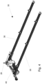
- the XY-guide assembly 30 comprises two spaced apart guides 36, 38 which span a width of the transport table 14, and a transverse guide 40 substantially orthogonal to said two spaced apart guides 36, 38 and spanning a distance between said two guides 36, 38.
- the marking tool 28 is moveably mounted on the transverse guide 40 and is moveable in a longitudinal direction of the transverse guide 40.
- the transverse guide 40 is moveably mounted on the two spaced apart guides 36, 38 and is moveable in a longitudinal direction of the two spaced apart guides 36, 38.
- the two spaced apart guides 36, 38 are fixedly connected to the stationary frame 12.
- Such an XY-guide assembly 30 provides a stable support for the marking tool 28.
- the guides 36, 38, 40 should be dimensioned rigidly enough so as to achieve the desired precision, without being influenced by the weight of the marking tool 28 as well as the forces exerted on the marking tool 28 when the marking of the sheet material S is performed.
- the sheet processing machine 10 further comprises a cross-guide portal 42 spanning a width of the transport table 14, wherein the processing tool 26 is moveably connected with the cross-guide portal 42 so as to be moveable back and forth along the Y-direction.
- the processing tool 26 may, in operation, be moved to process along the entire width of the sheet material S.
- the processing head carrying the processing tool 26 can be moved to every desired position with respect to the sheet material S to perform its processing.
- the processing head carrying the processing tool 26 may also be movably connected to the cross-guide portal 42 so as to be moveable along the Z-direction, i.e. perpendicular to the X-direction and the Y-direction so that the processing tool 26 can be moved towards and away from the sheet material S.
- the sheet processing machine 10 is further provided with a control system configured to control the movement of the marking tool 28 with respect to the stationary frame 12, and to operate the marking tool 28.
- the control system may also be configured to control the movement of the processing tool 26 with respect to the stationary frame 12, and to operate the processing tool 26.
- the control system may be configured to control the movement of the marking tool 28 with respect to the stationary frame 12 and/or to operate the marking tool 28 independently of and simultaneously with the controlling of the movement of the processing tool 26 with respect to the stationary frame 12 and/or the operating of the processing tool 26.
- the control system provides an automation of the sheet processing machine 10. It may be part of the machine or it may be implemented in a separate computer or IC.
- the control system may be dedicated hardware, implemented with dedicated software. Regardless of implementation, the control system may be preloaded with instructions to perform certain actions on the sheet material S.
- the sheet material S remains stationary during processing of the processing tool 26 on the sheet material S.
- the processing tool 26 may be a drill, a milling tool, a plasma cutter or a saw band.
- the marking tool 28 may be a milling tool, a drill, a laser, a powder marker, a scribing tool, or an inkjet marker. Other tools for processing or marking known in the art may also be used.
- the invention also relates to a method for processing sheet material.
- the method comprises providing a sheet processing machine 10 according to the invention, providing a sheet material S to be processed, transporting the sheet material S in an X-direction to a processing position, processing the sheet material S at a first side of the sheet material with the processing tool 26, optionally while moving the sheet material back and/or forth along the X-direction, and marking the sheet material S simultaneously with the processing at a second side of the sheet material S opposite the first side thereof.
- the first side is an upwardly directed and the second side is a downwardly directed side of the sheet material S.
- the sheet material S is preferably oriented substantially horizontally.
Landscapes
- Engineering & Computer Science (AREA)
- Mechanical Engineering (AREA)
- Physics & Mathematics (AREA)
- Optics & Photonics (AREA)
- Plasma & Fusion (AREA)
- Life Sciences & Earth Sciences (AREA)
- Forests & Forestry (AREA)
- Laser Beam Processing (AREA)
Claims (11)
- Plattenbearbeitungsmaschine (10), die versehen ist mit- einem stationären Rahmen (12), der einen Transporttisch (14) zum Transportieren und Tragen eines Plattenmaterials (S) umfasst, wobei der Transporttisch (14) einen Rollenförderer (16) umfassend eine Vielzahl von Rollen (18, 20) umfasst, und einen Spalt (22) zwischen zwei der mehreren Rollen (18, 20) umfasst, wobei der Transporttisch (14) eine Transportebene (24) aufweist, in welcher Ebene (24) das Plattenmaterial (S) im Betrieb bewegt wird, wobei die Transportebene (24) eine im Wesentlichen horizontale Ebene ist, so dass das Plattenmaterial (S) im Wesentlichen horizontal ausgerichtet ist;- ein Bearbeitungswerkzeug (26) zum Bearbeiten des Plattenmaterials (S) und das an einer ersten Seite der Transportebene (24), d. h. oberhalb der Transportebene (24), derart angeordnet ist, dass das Bearbeitungswerkzeug (26) im Betrieb an einer ersten Seite des Plattenmaterials (S) bearbeitet, wobei die erste Seite des Plattenmaterials (S) eine nach oben gerichtete Seite des Plattenmaterials (S) ist;dadurch gekennzeichnet, dass die Plattenbearbeitungsmaschine ferner umfasst:- ein Markierungswerkzeug (28) zum Markieren des Plattenmaterials (S) und das an einer zweiten Seite der Transportebene (24), d. h. unterhalb der Transportebene (24), derart angeordnet ist, dass das Markierungswerkzeug (28) im Betrieb auf einer zweiten, der ersten Seite gegenüberliegenden Seite des Plattenmaterials (S) markiert, wobei die zweite Seite des Plattenmaterials (S) eine nach unten gerichtete Seite des Plattenmaterials (S) ist; und- eine XY-Führungsbaugruppe (30), die in oder an dem Spalt (22) auf der zweiten Seite der Transportebene (24), d. h. unterhalb der Transportebene (24), angeordnet ist, und das Markierungswerkzeug (28) mit dem stationären Rahmen (12) verbindet und eine Bewegung des Markierungswerkzeugs (28) in Bezug auf den stationären Rahmen (12) ermöglicht,wobei sich das Markierungswerkzeug (28) in dem Spalt (22) nach oben in Richtung des Plattenmaterials (S) erstreckt und in Bezug auf den stationären Rahmen (12) entlang einer X-Richtung parallel zu einer Transportrichtung (32) des Rollenförderers (16) und in einer Y-Richtung senkrecht zu der X-Richtung und parallel zu der Transportebene (24) bewegbar ist, und wobei die Bewegung des Markierungswerkzeugs (28) in Bezug auf den stationären Rahmen (12) unabhängig von einer Bewegung des Bearbeitungswerkzeugs (26) in Bezug auf den stationären Rahmen (12) steuerbar ist.
- Plattenbearbeitungsmaschine nach Anspruch 1, die ferner einen Greifer umfasst, der im Betrieb das Plattenmaterial (S) ergreift und so angeordnet ist, dass er das Plattenmaterial (S) über den Rollenförderer (16) entlang der X-Richtung (32) hin und her bewegt.
- Plattenbearbeitungsmaschine nach einem der vorhergehenden Ansprüche, wobei die XY-Führungsbaugruppe (30) zwei voneinander beabstandete Führungen (36, 38) umfasst, die eine Breite des Transporttisches (14) überspannen, und eine Querführung (40), die im Wesentlichen orthogonal zu den beiden beabstandeten Führungen (36, 38) verläuft und einen Abstand zwischen den beiden Führungen (36, 38) überspannt, wobei das Markierungswerkzeug (28) beweglich an der Querführung (40) angebracht ist und in einer Längsrichtung der Querführung (40) beweglich ist, wobei die Querführung (40) beweglich an den beiden beabstandeten Führungen (36, 38) angebracht ist und in einer Längsrichtung der beiden beabstandeten Führungen (36, 38) bewegbar ist, und wobei die beiden voneinander beabstandeten Führungen (36, 38) fest mit dem stationären Rahmen (12) verbunden sind.
- Plattenbearbeitungsmaschine nach einem der vorhergehenden Ansprüche, ferner umfassend ein Querführungsportal (42), das sich über eine Breite des Transporttisches (14) erstreckt, wobei das Bearbeitungswerkzeug (26) beweglich mit dem Querführungsportal (42) verbunden ist, so dass es entlang der Y-Richtung hin- und herbewegt werden kann.
- Plattenbearbeitungsmaschine nach einem der vorhergehenden Ansprüche, die ferner mit einem Steuersystem ausgestattet ist, das so konfiguriert ist, dass es die Bewegung des Markierungswerkzeugs (28) in Bezug auf den stationären Rahmen (12) steuert und das Markierungswerkzeug (28) betreibt.
- Plattenbearbeitungsmaschine nach Anspruch 5, wobei das Steuersystem auch so konfiguriert ist, dass es die Bewegung des Bearbeitungswerkzeugs (26) in Bezug auf den stationären Rahmen (12) steuert und das Bearbeitungswerkzeug (26) betreibt.
- Plattenbearbeitungsmaschine nach Anspruch 6, wobei das Steuersystem so konfiguriert ist, dass es die Bewegung des Markierungswerkzeugs (28) in Bezug auf den stationären Rahmen (12) steuert und/oder das Markierungswerkzeug (28) unabhängig von und gleichzeitig mit der Steuerung der Bewegung des Bearbeitungswerkzeugs (26) in Bezug auf den stationären Rahmen (12) und/oder den Betrieb des Bearbeitungswerkzeugs (26) betreibt.
- Plattenbearbeitungsmaschine nach einem der vorhergehenden Ansprüche, wobei das Plattenmaterial (S) während der Bearbeitung des Bearbeitungswerkzeugs (26) auf dem Plattenmaterial (S) stationär bleibt.
- Plattenbearbeitungsmaschine nach einem der vorhergehenden Ansprüche, wobei das Bearbeitungswerkzeug (26) ein Bohrer, ein Fräswerkzeug, ein Plasmaschneider oder ein Sägeband ist.
- Plattenbearbeitungsmaschine nach einem der vorhergehenden Ansprüche, wobei das Markierungswerkzeug (28) ein Fräswerkzeug, ein Bohrer, ein Laser, ein Pulvermarker, ein Anreißwerkzeug oder ein Tintenstrahlmarker ist.
- Verfahren zum Bearbeiten von Plattenmaterial, umfassend:- Bereitstellen einer Plattenbearbeitungsmaschine (10) nach einem der vorhergehenden Ansprüche;- Bereitstellen eines zu bearbeitenden Plattenmaterials (S);- Transportieren des Plattenmaterials (S) in X-Richtung zu einer Bearbeitungsposition,- Bearbeiten des Plattenmaterials (S) an einer ersten Seite des Plattenmaterials mit dem Bearbeitungswerkzeug (26), optional während das Plattenmaterial entlang der X-Richtung hin- und/oder herbewegt wird; und- Markieren des Plattenmaterials (S) gleichzeitig mit der Bearbeitung an einer zweiten Seite des Plattenmaterials (S) gegenüber der ersten Seite davon, wobei die erste Seite eine nach oben gerichtete Seite und die zweite Seite eine nach unten gerichtete Seite des Plattenmaterials (S) ist, wobei das Plattenmaterial (S) im Wesentlichen horizontal ausgerichtet ist.
Applications Claiming Priority (2)
| Application Number | Priority Date | Filing Date | Title |
|---|---|---|---|
| NL2022696A NL2022696B1 (en) | 2019-03-08 | 2019-03-08 | A sheet processing machine and a method for processing sheet material |
| PCT/NL2020/050156 WO2020185077A1 (en) | 2019-03-08 | 2020-03-09 | A sheet processing machine and a method for processing flat workpieces |
Publications (3)
| Publication Number | Publication Date |
|---|---|
| EP3934867A1 EP3934867A1 (de) | 2022-01-12 |
| EP3934867C0 EP3934867C0 (de) | 2024-11-06 |
| EP3934867B1 true EP3934867B1 (de) | 2024-11-06 |
Family
ID=66286897
Family Applications (1)
| Application Number | Title | Priority Date | Filing Date |
|---|---|---|---|
| EP20712705.1A Active EP3934867B1 (de) | 2019-03-08 | 2020-03-09 | Maschine und verfahren zur bearbeitung von platten |
Country Status (4)
| Country | Link |
|---|---|
| US (1) | US20220063033A1 (de) |
| EP (1) | EP3934867B1 (de) |
| NL (1) | NL2022696B1 (de) |
| WO (1) | WO2020185077A1 (de) |
Families Citing this family (4)
| Publication number | Priority date | Publication date | Assignee | Title |
|---|---|---|---|---|
| CN112958829B (zh) * | 2020-12-25 | 2022-03-22 | 西安科技大学 | 金属棒夹紧式双段剪切下料装置及下料方法 |
| CN113134636A (zh) * | 2021-03-12 | 2021-07-20 | 杭州佳菱机械制造有限公司 | 一种大型多面多孔零部件自动化加工生产线 |
| CN113909901A (zh) * | 2021-10-08 | 2022-01-11 | 福建省华隆机械有限公司 | 一种加工中心与锯切水刀组合的设备及其加工方法 |
| CN117644396B (zh) * | 2023-12-13 | 2025-01-14 | 江苏天力建机电科技发展有限公司 | 一种铁路道岔平垫板钻孔装置及方法 |
Citations (2)
| Publication number | Priority date | Publication date | Assignee | Title |
|---|---|---|---|---|
| EP0470350A2 (de) * | 1990-08-07 | 1992-02-12 | ATG ELECTRONIC GmbH | Mehrspindelmaschine zum Bohren, Fräsen oder dergleichen |
| WO2009141708A1 (en) * | 2008-05-22 | 2009-11-26 | Biesse S.P.A. | Machine for machining wood components or the like |
Family Cites Families (7)
| Publication number | Priority date | Publication date | Assignee | Title |
|---|---|---|---|---|
| US3880028A (en) * | 1974-02-25 | 1975-04-29 | Ppg Industries Inc | Method and apparatus for monitoring and controlling glass cutting |
| DE19620391C2 (de) * | 1996-05-21 | 2001-12-13 | Carl Ingolf Lange | Bearbeitungsvorrichtung für flache Gegenstände |
| CA2624478A1 (en) * | 2005-10-07 | 2007-04-19 | Caretta Technology S.R.L. | Cutting unit with modular structure |
| ITTO20080497A1 (it) * | 2008-06-25 | 2009-12-26 | Bottero Spa | Metodo e macchina per il troncaggio di una lastra di vetro |
| JP6349970B2 (ja) * | 2014-05-30 | 2018-07-04 | 三星ダイヤモンド工業株式会社 | 基板分断方法並びに基板分断装置 |
| DE202014008305U1 (de) * | 2014-10-17 | 2014-10-30 | Hegla Gmbh & Co. Kg | Vorrichtung zum Aufteilen einer Glastafel, insbesondere Verbundglastafel, in einzelne Glasscheiben, insbesondere Verbundglasscheiben |
| CN108558192A (zh) * | 2018-06-29 | 2018-09-21 | 安徽智成数控科技有限公司 | 一种方便定位玻璃板材的玻璃切割机 |
-
2019
- 2019-03-08 NL NL2022696A patent/NL2022696B1/en active
-
2020
- 2020-03-09 US US17/428,089 patent/US20220063033A1/en not_active Abandoned
- 2020-03-09 WO PCT/NL2020/050156 patent/WO2020185077A1/en not_active Ceased
- 2020-03-09 EP EP20712705.1A patent/EP3934867B1/de active Active
Patent Citations (2)
| Publication number | Priority date | Publication date | Assignee | Title |
|---|---|---|---|---|
| EP0470350A2 (de) * | 1990-08-07 | 1992-02-12 | ATG ELECTRONIC GmbH | Mehrspindelmaschine zum Bohren, Fräsen oder dergleichen |
| WO2009141708A1 (en) * | 2008-05-22 | 2009-11-26 | Biesse S.P.A. | Machine for machining wood components or the like |
Non-Patent Citations (1)
| Title |
|---|
| VOORTMANMACHINERY: "CNC Heavy Plate Drilling, Cutting And Milling | Voortman V325 | Steel Fabrication", YOUTUBE, 6 November 2017 (2017-11-06), pages 1, XP054980113, Retrieved from the Internet <URL:https://www.youtube.com/watch?v=8qg3qn9OPrM> [retrieved on 20200116] * |
Also Published As
| Publication number | Publication date |
|---|---|
| EP3934867A1 (de) | 2022-01-12 |
| WO2020185077A1 (en) | 2020-09-17 |
| NL2022696B1 (en) | 2020-09-17 |
| EP3934867C0 (de) | 2024-11-06 |
| US20220063033A1 (en) | 2022-03-03 |
Similar Documents
| Publication | Publication Date | Title |
|---|---|---|
| EP3934867B1 (de) | Maschine und verfahren zur bearbeitung von platten | |
| KR101537135B1 (ko) | 워크 가공 장치 및 워크 가공 방법 | |
| US4302144A (en) | Work changing mechanism for machine tools | |
| JP5026884B2 (ja) | 自動工具交換装置を有する工作機械 | |
| US8089024B2 (en) | Torch spacing apparatus | |
| EP2138264A1 (de) | Sekundäre Positioniervorrichtung zur maschinellen Werkstückbearbeitung | |
| US20160167187A1 (en) | Machine Tool Having a Number of Multispindle Spindle Assemblies | |
| US20050121109A1 (en) | Method and machining installation for the machining of wood workpieces | |
| EP2145744A1 (de) | Vorrichtung und Verfahren zum Schneiden von Platten. | |
| CN102950511A (zh) | 带有两个垂直的工件主轴的自动装载的机床 | |
| CN107598368B (zh) | 激光切割机 | |
| US20220023974A1 (en) | Pipe processing machine for cutting pipes or profiled sections using a laser beam | |
| US4449986A (en) | Machine for guiding numerically controlled supports for tools used in woodworking operation | |
| KR20120083639A (ko) | 공작기계의 자동 공구 교환장치 | |
| EP0539633B1 (de) | Portalwerkzeugmaschine | |
| KR20180043254A (ko) | 공작 기계 | |
| EP1231008A1 (de) | Plattenbearbeitungsmaschine | |
| CN105312967B (zh) | 双主轴机床 | |
| CN105014454B (zh) | 用于加工工件的机床和操作这种机床的方法 | |
| CN108340208A (zh) | 加工刚性和半刚性平面材料的数控机床中移动工具的结构 | |
| US10695842B2 (en) | Horizontal lathe machine with a mid-spindle and two tooling turrets | |
| KR101801202B1 (ko) | 다축 머시닝 센터 | |
| KR100865323B1 (ko) | 대형 시엔시 머신 장착용 보조 고속 이송 장치 | |
| CN106715046B (zh) | 加工设备 | |
| JP2014065131A (ja) | 工作機械システム |
Legal Events
| Date | Code | Title | Description |
|---|---|---|---|
| STAA | Information on the status of an ep patent application or granted ep patent |
Free format text: STATUS: UNKNOWN |
|
| STAA | Information on the status of an ep patent application or granted ep patent |
Free format text: STATUS: THE INTERNATIONAL PUBLICATION HAS BEEN MADE |
|
| PUAI | Public reference made under article 153(3) epc to a published international application that has entered the european phase |
Free format text: ORIGINAL CODE: 0009012 |
|
| STAA | Information on the status of an ep patent application or granted ep patent |
Free format text: STATUS: REQUEST FOR EXAMINATION WAS MADE |
|
| 17P | Request for examination filed |
Effective date: 20210913 |
|
| AK | Designated contracting states |
Kind code of ref document: A1 Designated state(s): AL AT BE BG CH CY CZ DE DK EE ES FI FR GB GR HR HU IE IS IT LI LT LU LV MC MK MT NL NO PL PT RO RS SE SI SK SM TR |
|
| DAV | Request for validation of the european patent (deleted) | ||
| DAX | Request for extension of the european patent (deleted) | ||
| GRAJ | Information related to disapproval of communication of intention to grant by the applicant or resumption of examination proceedings by the epo deleted |
Free format text: ORIGINAL CODE: EPIDOSDIGR1 |
|
| STAA | Information on the status of an ep patent application or granted ep patent |
Free format text: STATUS: GRANT OF PATENT IS INTENDED |
|
| GRAP | Despatch of communication of intention to grant a patent |
Free format text: ORIGINAL CODE: EPIDOSNIGR1 |
|
| INTG | Intention to grant announced |
Effective date: 20240528 |
|
| GRAS | Grant fee paid |
Free format text: ORIGINAL CODE: EPIDOSNIGR3 |
|
| GRAA | (expected) grant |
Free format text: ORIGINAL CODE: 0009210 |
|
| STAA | Information on the status of an ep patent application or granted ep patent |
Free format text: STATUS: THE PATENT HAS BEEN GRANTED |
|
| AK | Designated contracting states |
Kind code of ref document: B1 Designated state(s): AL AT BE BG CH CY CZ DE DK EE ES FI FR GB GR HR HU IE IS IT LI LT LU LV MC MK MT NL NO PL PT RO RS SE SI SK SM TR |
|
| REG | Reference to a national code |
Ref country code: GB Ref legal event code: FG4D |
|
| REG | Reference to a national code |
Ref country code: CH Ref legal event code: EP |
|
| REG | Reference to a national code |
Ref country code: DE Ref legal event code: R096 Ref document number: 602020040776 Country of ref document: DE |
|
| REG | Reference to a national code |
Ref country code: IE Ref legal event code: FG4D |
|
| U01 | Request for unitary effect filed |
Effective date: 20241120 |
|
| U07 | Unitary effect registered |
Designated state(s): AT BE BG DE DK EE FI FR IT LT LU LV MT NL PT RO SE SI Effective date: 20241127 |
|
| U20 | Renewal fee for the european patent with unitary effect paid |
Year of fee payment: 6 Effective date: 20250304 |
|
| PG25 | Lapsed in a contracting state [announced via postgrant information from national office to epo] |
Ref country code: HR Free format text: LAPSE BECAUSE OF FAILURE TO SUBMIT A TRANSLATION OF THE DESCRIPTION OR TO PAY THE FEE WITHIN THE PRESCRIBED TIME-LIMIT Effective date: 20241106 Ref country code: IS Free format text: LAPSE BECAUSE OF FAILURE TO SUBMIT A TRANSLATION OF THE DESCRIPTION OR TO PAY THE FEE WITHIN THE PRESCRIBED TIME-LIMIT Effective date: 20250306 |
|
| PG25 | Lapsed in a contracting state [announced via postgrant information from national office to epo] |
Ref country code: ES Free format text: LAPSE BECAUSE OF FAILURE TO SUBMIT A TRANSLATION OF THE DESCRIPTION OR TO PAY THE FEE WITHIN THE PRESCRIBED TIME-LIMIT Effective date: 20241106 |
|
| PG25 | Lapsed in a contracting state [announced via postgrant information from national office to epo] |
Ref country code: NO Free format text: LAPSE BECAUSE OF FAILURE TO SUBMIT A TRANSLATION OF THE DESCRIPTION OR TO PAY THE FEE WITHIN THE PRESCRIBED TIME-LIMIT Effective date: 20250206 |
|
| PG25 | Lapsed in a contracting state [announced via postgrant information from national office to epo] |
Ref country code: GR Free format text: LAPSE BECAUSE OF FAILURE TO SUBMIT A TRANSLATION OF THE DESCRIPTION OR TO PAY THE FEE WITHIN THE PRESCRIBED TIME-LIMIT Effective date: 20250207 |
|
| PG25 | Lapsed in a contracting state [announced via postgrant information from national office to epo] |
Ref country code: PL Free format text: LAPSE BECAUSE OF FAILURE TO SUBMIT A TRANSLATION OF THE DESCRIPTION OR TO PAY THE FEE WITHIN THE PRESCRIBED TIME-LIMIT Effective date: 20241106 |
|
| PGFP | Annual fee paid to national office [announced via postgrant information from national office to epo] |
Ref country code: GB Payment date: 20250326 Year of fee payment: 6 |
|
| PG25 | Lapsed in a contracting state [announced via postgrant information from national office to epo] |
Ref country code: RS Free format text: LAPSE BECAUSE OF FAILURE TO SUBMIT A TRANSLATION OF THE DESCRIPTION OR TO PAY THE FEE WITHIN THE PRESCRIBED TIME-LIMIT Effective date: 20250206 |
|
| PG25 | Lapsed in a contracting state [announced via postgrant information from national office to epo] |
Ref country code: SM Free format text: LAPSE BECAUSE OF FAILURE TO SUBMIT A TRANSLATION OF THE DESCRIPTION OR TO PAY THE FEE WITHIN THE PRESCRIBED TIME-LIMIT Effective date: 20241106 |
|
| PG25 | Lapsed in a contracting state [announced via postgrant information from national office to epo] |
Ref country code: SK Free format text: LAPSE BECAUSE OF FAILURE TO SUBMIT A TRANSLATION OF THE DESCRIPTION OR TO PAY THE FEE WITHIN THE PRESCRIBED TIME-LIMIT Effective date: 20241106 |
|
| PG25 | Lapsed in a contracting state [announced via postgrant information from national office to epo] |
Ref country code: CZ Free format text: LAPSE BECAUSE OF FAILURE TO SUBMIT A TRANSLATION OF THE DESCRIPTION OR TO PAY THE FEE WITHIN THE PRESCRIBED TIME-LIMIT Effective date: 20241106 |
|
| PLBE | No opposition filed within time limit |
Free format text: ORIGINAL CODE: 0009261 |
|
| STAA | Information on the status of an ep patent application or granted ep patent |
Free format text: STATUS: NO OPPOSITION FILED WITHIN TIME LIMIT |
|
| PG25 | Lapsed in a contracting state [announced via postgrant information from national office to epo] |
Ref country code: MC Free format text: LAPSE BECAUSE OF FAILURE TO SUBMIT A TRANSLATION OF THE DESCRIPTION OR TO PAY THE FEE WITHIN THE PRESCRIBED TIME-LIMIT Effective date: 20241106 |
|
| 26N | No opposition filed |
Effective date: 20250807 |
|
| REG | Reference to a national code |
Ref country code: CH Ref legal event code: H13 Free format text: ST27 STATUS EVENT CODE: U-0-0-H10-H13 (AS PROVIDED BY THE NATIONAL OFFICE) Effective date: 20251024 |