EP0570103A2 - Ferngesteuertes Sicherheitssystem - Google Patents
Ferngesteuertes Sicherheitssystem Download PDFInfo
- Publication number
- EP0570103A2 EP0570103A2 EP93302586A EP93302586A EP0570103A2 EP 0570103 A2 EP0570103 A2 EP 0570103A2 EP 93302586 A EP93302586 A EP 93302586A EP 93302586 A EP93302586 A EP 93302586A EP 0570103 A2 EP0570103 A2 EP 0570103A2
- Authority
- EP
- European Patent Office
- Prior art keywords
- code
- transmitter
- codes
- receiver
- digital signal
- Prior art date
- Legal status (The legal status is an assumption and is not a legal conclusion. Google has not performed a legal analysis and makes no representation as to the accuracy of the status listed.)
- Granted
Links
Images


Classifications
-
- G—PHYSICS
- G07—CHECKING-DEVICES
- G07C—TIME OR ATTENDANCE REGISTERS; REGISTERING OR INDICATING THE WORKING OF MACHINES; GENERATING RANDOM NUMBERS; VOTING OR LOTTERY APPARATUS; ARRANGEMENTS, SYSTEMS OR APPARATUS FOR CHECKING NOT PROVIDED FOR ELSEWHERE
- G07C9/00—Individual registration on entry or exit
- G07C9/00174—Electronically operated locks; Circuits therefor; Nonmechanical keys therefor, e.g. passive or active electrical keys or other data carriers without mechanical keys
- G07C9/00182—Electronically operated locks; Circuits therefor; Nonmechanical keys therefor, e.g. passive or active electrical keys or other data carriers without mechanical keys operated with unidirectional data transmission between data carrier and locks
-
- H—ELECTRICITY
- H04—ELECTRIC COMMUNICATION TECHNIQUE
- H04K—SECRET COMMUNICATION; JAMMING OF COMMUNICATION
- H04K1/00—Secret communication
-
- G—PHYSICS
- G07—CHECKING-DEVICES
- G07C—TIME OR ATTENDANCE REGISTERS; REGISTERING OR INDICATING THE WORKING OF MACHINES; GENERATING RANDOM NUMBERS; VOTING OR LOTTERY APPARATUS; ARRANGEMENTS, SYSTEMS OR APPARATUS FOR CHECKING NOT PROVIDED FOR ELSEWHERE
- G07C9/00—Individual registration on entry or exit
- G07C9/00174—Electronically operated locks; Circuits therefor; Nonmechanical keys therefor, e.g. passive or active electrical keys or other data carriers without mechanical keys
- G07C9/00182—Electronically operated locks; Circuits therefor; Nonmechanical keys therefor, e.g. passive or active electrical keys or other data carriers without mechanical keys operated with unidirectional data transmission between data carrier and locks
- G07C2009/00238—Electronically operated locks; Circuits therefor; Nonmechanical keys therefor, e.g. passive or active electrical keys or other data carriers without mechanical keys operated with unidirectional data transmission between data carrier and locks the transmittted data signal containing a code which is changed
- G07C2009/00253—Electronically operated locks; Circuits therefor; Nonmechanical keys therefor, e.g. passive or active electrical keys or other data carriers without mechanical keys operated with unidirectional data transmission between data carrier and locks the transmittted data signal containing a code which is changed dynamically, e.g. variable code - rolling code
-
- G—PHYSICS
- G07—CHECKING-DEVICES
- G07C—TIME OR ATTENDANCE REGISTERS; REGISTERING OR INDICATING THE WORKING OF MACHINES; GENERATING RANDOM NUMBERS; VOTING OR LOTTERY APPARATUS; ARRANGEMENTS, SYSTEMS OR APPARATUS FOR CHECKING NOT PROVIDED FOR ELSEWHERE
- G07C9/00—Individual registration on entry or exit
- G07C9/00174—Electronically operated locks; Circuits therefor; Nonmechanical keys therefor, e.g. passive or active electrical keys or other data carriers without mechanical keys
- G07C2009/00753—Electronically operated locks; Circuits therefor; Nonmechanical keys therefor, e.g. passive or active electrical keys or other data carriers without mechanical keys operated by active electrical keys
- G07C2009/00769—Electronically operated locks; Circuits therefor; Nonmechanical keys therefor, e.g. passive or active electrical keys or other data carriers without mechanical keys operated by active electrical keys with data transmission performed by wireless means
- G07C2009/00793—Electronically operated locks; Circuits therefor; Nonmechanical keys therefor, e.g. passive or active electrical keys or other data carriers without mechanical keys operated by active electrical keys with data transmission performed by wireless means by Hertzian waves
Definitions
- the present invention relates to the art of remote control of security systems and, more particularly, to controlling the locking and unlocking functions of a lock, such as on a motor vehicle's door or trunk lid or the like.
- Remote control security systems are known in the art for controlling the locking and unlocking functions of a lock mounted on a motor vehicle and such systems typically comprise a receiver mounted on the vehicle proximate to the lock to be controlled and a portable handheld transmitter located remote from the receiver.
- a system such as that described above is disclosed in my U.S. Patent No. 4,881,148, the disclosure of which is incorporated herein by reference. That patent discloses a system wherein a receiver has a memory which stores one or more security codes, each of which identifies a transmitter from which the receiver will validly receive a transmitted signal.
- Each transmitter is provided with a plurality of actuatable switches, each representative of a control function to be performed by the lock, such as an unlock function, or a lock function, or an unlock a truck lid function.
- each transmitter includes circuitry that responds to the actuation of one of the switches to transmit a digital signal which includes a security code which uniquely identifies the transmitter from that of a plurality of similar transmitters, along with a function code representative of the particular control function to be performed by the lock.
- a receiver receives such a digital signal it compares the received security code with each stored security code to determine if a match exists indicative that the receiver may validly receive the digital signal and respond thereto. If a match takes place, then the receiver responds to the function code for performing the control function requested, such as lock or unlock a vehicle door.
- a concern with respect to such a system is that a would-be thief desiring entry into a locked vehicle may record the transmitted digital signal with appropriate radio frequency receiving equipment. Such recorded information may then be employed by such a thief for purposes of gaining access into such a locked vehicle.
- both the transmitter and the receiver may be provided with code generators which generate a succession of differently coded signals such that the security code is updated in the same manner at both the transmitter and the receiver after each operation.
- a system of this type is disclosed in the U.S. Patent to Bongard et al. 4,596,985.
- the security code sometimes referred to as access code or identity code
- This may present a difficulty in that by making changes to the security code, then the security code transmitted by a transmitter may inadvertently be changed to a code that permits unwanted access to a receiver having the same security code.
- the prior art noted above does not provide that the security code remain fixed and that the transmitted digital signal include an additional code which changes after each transmission such that the change is dependent upon information contained in the security code.
- the additional code sometimes referred to herein as a sequence control code, be received at the receiver for comparison with a similar sequence control code and which, after each operation, is updated by changing its digital value dependent upon information contained in the security code stored at the receiver.
- a transmitter remotely controls the locking and unlocking functions of a lock mounted on a vehicle or the like wherein the transmitter includes a plurality of selectively actuatable switches each representative of a function to be performed by the lock, such as lock or unlock a vehicle door or unlock a trunk lid.
- a digital signal is transmitted by the transmitter with the digital signal including a first portion having a multi-bit security code uniquely identifying the transmitter from that of similar transmitters, a multi-bit sequence control code that is sequentially changed in response to each actuation of one of the switches and a multi-bit function code identifying one of a plurality of the control functions to be performed by the lock.
- the transmitter responds to each actuation of one of the switches for sequentially changing the digital value of the sequence control code with each change being dependent upon information contained in the security code that identifies the transmitter.
- a receiver for use in receiving a digital signal as described above and wherein the receiver includes a memory that stores a multi-bit receiver security code which identifies a specific transmitter from which the receiver may validly receive a transmitted digital signal together with circuitry for comparing the received security code with the stored security code to determine if the codes match.
- a multi-bit sequence control code is also stored in memory in the receiver and circuitry is provided which responds to each occurrence of a match between the security codes for reading the stored sequence control code and changing its digital value to define an updated sequence control code having a digital value dependent upon information contained in the stored receiver security code.
- the updated sequence control code and the stored sequence control word are compared to determine whether a match exists and, if so, the lock is controlled to perform the function defined by the received function control code.
- a remote control security system including a receiver as described hereinabove along with at least one transmitter as described hereinabove.
- the transmitted digital signal includes a second portion having a multi-bit second code and wherein the codes in the first portion of the transmitted digital signal are scrambled in accordance with one of a plurality of scrambling algorithms and wherein the second code in the second portion of the transmitted digital signal includes information as to which one of the plurality of scrambling algorithms is employed.
- the receiver de-scrambles the codes in the first portion of the received digital signal in dependence upon information contained in the received second code.
- the codes in the first portion of the transmitted digital signal are arranged in order for transmission in accordance with one of a plurality of transmission order algorithms and that the second code includes information as to which one of the transmission order algorithms was employed for arranging the order of the codes.
- the receiver rearranges the order of the codes in the first portion of the received digital signal based upon information contained in the received second code.
- FIG. 1 shows a remote control A for selectively operating a door lock mechanism B, door unlock mechanism C or trunk solenoid D to release the trunk of a motor vehicle.
- System A includes a transmitting unit T for creating a coded digital signal S to be transmitted to receiver unit R, whereby the doors of the vehicle can be locked or unlocked or the trunk can be released at will from a distance of at least 20-50 feet.
- Transmitting unit T includes a microcomputer having appropriate internal PROMs, EEPROMs and RAMs programmed to perform the functions of the system, as hereinafter described, and having sufficient I/O terminals controlled by selector means or switches 12, 14, and 16.
- switch 12 is depressed when system A is to lock the doors of the vehicle by operating door lock mechanism B.
- switch 14 is manually operated to unlock the vehicle doors by actuating door unlock mechanism C.
- the trunk solenoid D or mechanism for unlatching the vehicle trunk lock is actuated by depressing manual switch 16.
- a power up circuit 20 is actuated to direct power to the microcomputer 10 and actuate oscillators 30 and 32.
- switches 12, 14, and 16 power system A and cause a single transmission of a coded signal. Thereafter, circuit 20 is deactivated to await a new requested function.
- Oscillator 30 has a nominal frequency of 315 MHz, in the preferred embodiment, which frequency is essentially the same frequency employed for common garage door operators. Whereas the invention is described herein with reference to an RF system, it may also be practiced with an IR system.
- Clock oscillator 32 is unregulated in that it does not have a crystal control and may vary as to its frequency with temperature changes and manufacturing tolerances. The output of oscillator 32 is used to time the function of microcomputer 10 to shift output line 38 to a logic 1 whenever a binary 1 is to be transmitted by antenna 36.
- Microcomputer output line 38 is one input of AND gate 39 having a second input controlled by the output of oscillator 30.
- the signal in output line 37 of gate 39 is a series of binary conditions (logic 0 and logic 1) superimposed on a 315 MHz carrier. Consequently, transmitted signal S, when microcomputer 10 is powered by circuit 20, will be a series of pulses having a length or duration controlled by the logic in line 38. Lines P are power lines actuated upon command of circuit 20.
- the code in signal S is binary, with a binary 1 and a binary 0 being distinguished from each other by having a difference in length or duration.
- This pulse length is controlled by the frequency of oscillator 32 which is not a high priced oscillator with quartz control; therefore, the relationship between a binary 0 and a binary 1 for the identification code in transmitted signal S is the relative pulse lengths of a logic 1 and a logic 0.
- These lengths vary according to the particular frequency of oscillator 32 but maintain their numerical relationship since they are based upon counts of the clock in line 34. In this manner, oscillator 32 can be relatively inexpensive but the frequency or clock in line 34 will not be identical from one transmitter T to another transmitter. Indeed, during different operating conditions in a particular transmitting unit the clock in line 34 can drift in frequency.
- power up circuit 20 which includes a battery (normal 5.0 volts), directs power to the microcomputer for a time which is controlled by the microcomputer. The length of the time the microcomputer maintains power is sufficient to transmit one control signal.
- This signal includes, in practice, a wake up signal, at least one initiation bit, thirty-two bits of security code, twenty-four bits of sequence control code, eight bits of checksum code and eight bits of function code to indicate which switch 12-16 has been closed.
- transmitting unit T is a handheld key ring having an appropriate array of finger tip switches 12-16, in a case 50 which can include a key ring 52 on a swivel connection 54.
- Transmitter case 50 is a small hollow housing containing the transmitter circuitry and a power source, such as a battery. The case is adapted for easy transportation in a person's pocket.
- the hand-held case 50 is retained by the operator of the vehicle so that as the operator approaches the vehicle, signal S can be transmitted to receiver R by merely depressing one of the finger operated switches 12-16 mounted in the case 50 and manually operable from outside of the case.
- the microcomputer 10 of the transmitter is provided with internal memories including PROMs, EEPROMs and RAMs. As is well known, such memories include registers for storing multi-bit codes. Whereas these registers are internal of the microcomputer 10, four of these registers are illustrated in Fig. 1 to assist in the explanation of the invention. These registers include a security code register 40, a sequence control code register 42, a function code control register 44 and a checksum code register 46. Registers 40 and 42 are in the EEPROM memory whereas registers 44 and 46 are in RAM.
- the security code register 40 contains a fixed code which uniquely identifies the transmitter T from that of other similar transmitters.
- the register contains a security code which is fixed in the transmitter by the manufacturer and may be implemented in a manner described hereinbefore with my previous U.S. Patent No. 4,881,148.
- the security code preferably takes the form of four eight bit bytes.
- sequence control code register stores a sequence control code which is preferably twenty-four bits long divided into three eight bit bytes.
- sequence control code which is preferably twenty-four bits long divided into three eight bit bytes.
- the digital value of the sequence control code is changed each time one of the switches 12, 14 or 16 is actuated and, hence, this is a sequentially changing code.
- This code is changed in accordance with one of a plurality of sequence control algorithms stored in a look-up table in the transmitter microcomputer 10. Also, as will be brought out in greater detail hereinafter, the determination as to which one of the plurality of sequence control algorithms to be employed is determined by examining information contained in the security code stored in register 40.
- a function code register 44 serves to temporarily store the function code to be transmitted as part of a transmitted digital signal S. This preferably takes the form of an eight bit coded byte with the bits being arranged in response to actuation of one of the switches 12, 14, 16 so that the function represented thereby is to either lock the vehicle door, unlock the vehicle door or unlock the trunk,lid by actuating the trunk solenoid.
- checksum code register 46 Another register in the microcomputer 10 is a checksum code register 46.
- This register contains an error detecting code known as a checksum code. This code is placed into the register by the microcomputer under program control in a known manner. For example, the data to be transmitted is examined and an eight bit checksum code is placed into the register for use in verifying the accuracy of the transmitted signal.
- the transmitted digital signal S is illustrated in Fig. 2 and it includes a wake up portion 11 and which may comprise a single bit, but which is of an elongated duration such as on the order of twelve milliseconds and this is followed by a start or initiation portion 13 and which may comprise four bits.
- the checksum code 15 includes 8 bits and the security code 17 contains 32 bits.
- the sequence control code 19 contains 24 bits and the function code 21 contains eight bits.
- the digital signal is transmitted in the order of the wake up code 11, followed by the initiation code 13. This is followed by an eight bit checksum code, four eight bit bytes of security code, three eight bit bytes of sequence code and an eight bit function code.
- the checksum code in this embodiment of the invention will always be in the same place.
- this code may be the first byte of the nine bytes which follow the transmission of the initiation bits. The remaining eight bytes may be varied in sequence and/or scrambled as will be discussed hereinafter. Moreover, the digital value of the sequence control code is changed with each transmission of a digital signal.
- the receiver R includes an RF detector 60 tuned to the transmitted frequency of 315 MHz so that, as the digital signal S is received at the receiver's antenna 61, the detector recognizes the frequency of the signal and allows the first portion including the wake up portion 11 to pass to a wake up signal detector 62.
- the detector 62 checks to see if the wake up condition is proper and, if so, it activates the wake up circuit 64.
- Circuit 64 acts as a power up circuit for supplying operating voltage, such as 5 volts, to the receiver's microcomputer 80. The operating voltage is monitored by a low voltage detector 68 to permit operation of the circuitry so long as the voltage does not drop below a selected level.
- the data in the received digital signal S is supplied to the microcomputer 80 and is clocked in by clock pulses obtained from a clock oscillator 82.
- the microcomputer 80 includes a plurality of internal memories including PROMs, RAMs and EEPROMs.
- the internal memories are programmed to perform the functions to be described in greater detail hereinafter.
- register 100 stores a security code A that uniquely identifies a transmitter from which the receiver may validly receive a digital signal.
- the code set into register 100 may be placed in the memory at the factory or may be programmed in the field in the manner as described in my previous U.S. Patent No. 4,881,148.
- the security code is generated by means of an algorithm which has the capability of generating numbers in a random, but not repeatable, fashion. This code is thirty-two bits in length and is divided into four eight bit data bytes.
- a second security code register 104 is provided, identical to that of register 100, but which includes a security code B which is uniquely different from that of security code A in register 100.
- the receiver includes a companion register 102 which has been programmed to contain a multi-bit sequence control code. As discussed herein with respect to the transmitter, this code is a twenty-four bit code divided into three eight bit bytes. This code is varied by a predetermined amount, known only to the manufacturer, each time the receiver has determined that it has received a valid digital signal, as will be described in detail hereinafter. Since it may be desirable to validly receive a digital signal from a second transmitter, a second sequence control code is stored in a second register 106 and in a like manner this sequence control code is changed each time the receiver has determined that it has validly received a digital signal from the second transmitter (or B transmitter)
- a pair of registers located in internal memory of the microprocessor 80 and these include a function code register 108 and a checksum code register 110. These are temporary memories and respectively serve to receive and store the function code and checksum code portions of the digital signal S received from the transmitter T.
- the receiver validly receives a digital signal from a transmitter, it will then decode the function code in register 108 and perform one of the door lock control functions such as locking a vehicle door or unlocking a vehicle door or actuating a trunk solenoid by way of suitable load drivers 120 controlled by the microcomputer 80.
- Fig. 3 illustrates the flow chart showing the manner in which the microcomputer in the transmitter is programmed in accordance with the present invention.
- the transmitter is at rest in a standby condition sometimes known as a power-down condition, and this is indicated as step 200 in Fig. 3.
- the microcomputer is now awaiting closure of one of the switches 12, 14 or 16.
- step 202 the microcomputer responds to the closure of one of the switches 12, 14 or 16 and initially actuates the power up circuit 20 in accordance with step 204 for purposes of applying power on lines P to the various circuits within the transmitter.
- step 206 the microcomputer is programmed to read the actuated switch to determine which switch 12, 14 or 16 was actuated and then store the function code associated with that switch in the function code register 44 in accordance with step 208.
- the function code stored in the register 44 now represents the specific request, such as lock the vehicle door or unlock the vehicle door or unlock the trunk lid.
- step 210 the microcomputer reads the present or old sequence control code from the register 42 in order to update the sequence control code in accordance with step 212.
- the computer performs a read function at step 214 wherein the security code register is read to obtain the security code for this transmitter. Having obtained the security code from register 40, the computer now reads from a look-up table A, pursuant to step 216, to determine which one of a plurality of sequence control variation algorithms is to be employed in determining the new sequence control code in accordance with step 218. Once the correct algorithm has been obtained from Table A in accordance with step 216, the next or new sequence control code is determined to obtain an updated sequence control code in accordance with step 212. This new sequence control code is then stored in the sequence control register 42 pursuant to step 220.
- the security code SC is comprised of four eight bit bytes.
- the most significant bits of these bytes may respectively be referred to as bits A, B, C and D and which are arranged in the lefthand column under the title ABCD.
- Sixteen variations of the digital value of this four bit number are represented in Table A, each providing a different algorithm for changing the present sequence control code to the next digital value of the sequence control code. For example, if the bits ABCD have a digital value of 0010, then the new sequence control code is determined by taking the old or present sequence control code and incrementing it by five. Similarly, if the digital value of the word ABCD in Table A is 0101, then the sequence control code is incremented by eleven to obtain the new digital value of the sequence control code. It is noted that the last eight algorithms in this Table provide for a decrement in the value of the sequence control code.
- the transmitter microcomputer calculates the checksum code by examining the bits in the security code, the sequence control code and the function code. A binary addition is performed on these eight bytes in order to calculate the checksum code.
- the calculated checksum code is then stored in the transmitter checksum code register 46 prior to assembling the various bytes for transmission in the digital signal S.
- the bits in each of the bytes forming the security code SC, the sequence control code SSC and the function code are scrambled in accordance with one of a plurality of scrambling algorithms as set forth in Table B below.
- the scrambling algorithm employed is determined by examining the four most significant bits of the checksum code.
- SCC-1 refers to the first byte of the sequence control code SCC.
- a checksum code of 00110000 assume a checksum code of 00110000.
- An examination of the four most significant bits indicates that the scrambling algorithm employed is algorithm No. 4 which directs that each byte of the data to be transmitted (with the exception of the checksum code) be combined in an exclusive OR manner with the first byte SCC-1 of the sequence control code.
- step 228 the programmed microcomputer selects the scrambling method to be employed by using the four most significant bits of the checksum code (represented at 230) to address Table B, represented at 232, in order to fetch one of the sixteen scrambling algorithms to be used.
- the bits within the data bytes, with the exception of the checksum code, are then scrambled in accordance with the selected scrambling algorithm in step 234 with the scrambled data then being stored in accordance with step 236 in registers 40, 42 and 44.
- the eight data bytes to be transmitted include four bytes of security code, three bytes of sequence control code and one byte of function code.
- the scrambled bytes may be transmitted in an order other than that as depicted in Fig. 2.
- the checksum byte is always in the same position. In the example given herein, the checksum byte is in the byte 1 position of the nine bytes following the wake up and initiation bits.
- the remaining eight data bytes are transmitted in one of sixteen different transmission orders as set forth in Table C below.
- output order No. 4 may take the following sequence: SCC1, SC1, SC2, SC3, SC4, function code, SCC2 and SCC3 (it being understood that SC1 stands for security code byte one, etc., whereas SCC1 stands for sequence control code byte 1, etc.).
- output order No. 4 may take the following sequence: SCC1, SC1, SC2, SC3, SC4, function code, SCC2 and SCC3 (it being understood that SC1 stands for security code byte one, etc., whereas SCC1 stands for sequence control code byte 1, etc.).
- output order No. 8 (checksum code xxxx0111) may require the following transmission order: function code, SC3, SCC2, SC1, SCC3, SC4, SCC1 and SC2.
- Table C is contained in a look-up memory in the transmitter's microcomputer in a known manner.
- step 2308 the transmitter's microcomputer selects the order in which to output the data bytes described hereinabove. To do so, the microcomputer examines the four least significant bits for the checksum codes stored in register 46, and uses those bits to access Table C containing the order information. The data to be transmitted is then re-ordered according to the order information read from look-up Table C. Data is then transmitted in the new order. The transmission is performed in step 244, wherein the wake up and initiation bits are initially transmitted, followed by the checksum byte and the eight data bytes (organized in the new order) representing the security code, the sequence control code and the function code. The transmitter is then powered down to await a switch closure commanding another transmission of a digital signal.
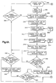
- Fig. 4 presents a flow chart showing the manner in which the microcomputer in the receiver R is programmed to accomplish various functions to be described herein.
- the receiver is in a power-down standby condition awaiting reception of a digital signal S from a transmitter, such as transmitter T.
- the wake-up bit will activate the wake up signal detector 62 and, as represented in step 302, will cause the wake-up circuit 64 to power up and provide power to the microcomputer 80 within the receiver.
- step 304 following the microcomputer's usual initiation steps, the microcomputer responds to the start or initiation portion of the digital signal to read the incoming digital signal and store same in the temporary registers in the microcomputer.
- the incoming digital signal is scrambled and the data bytes are out of order with the exception of the checksum code.
- This code is always in the same place. In the example being described it is in byte position one of the nine bytes that follow the initiation and wake up bits.
- the checksum code byte is stored in the checksum code register 110 at the receiver R.
- step 306 the four least significant bits of the checksum code stored in the receiver register 110 are examined to determine which of a plurality of sixteen transmission orders was employed in transmitting the eight data bytes to the receiver.
- step 310 the four least significant bits of the checksum code are used to access a look-up table (indicated at step 308) in the receiver's microcomputer memory.
- This table is the same Table C discussed hereinbefore.
- the four least significant bits of the checksum code are 0101, order No. 6 will be retrieved from Table C. That order may have the data bytes arranged as follows: SC1, SCC1, function code, SC3, SCC2, SC2, SCC3 and SC4.
- the data bytes are now placed in the correct order and stored in appropriate temporary memory registers in the receiver's microcomputer.
- step 312 the receiver's microcomputer examines the four most significant bits of the checksum code stored in the microcomputer's register 110. From the previous discussion of Table B it will be recalled that the four most significant,bits of the checksum code determine which one of sixteen scrambling algorithms was employed at the transmitter to scramble the eight data bytes. Similarly, the four most significant bits of the checksum code received and stored in the checksum code register 110 at the receiver R are used to choose a complementary de-scrambling method for restoring the data bytes to their original form. Consequently, the inverse of Table B is stored in a look-up table B' in the receiver's microcomputer, such as in ROM.
- This Table B' is like Table B, except that the stored instructions accomplish the de-scrambling of the bytes scrambled according to Table B.
- the microcomputer examines the four most significant bits of the checksum code in step 312 and then obtains from Table B', in accordance with step 314, the correct de-scrambling method for purposes of performing a reverse scrambling operation in accordance with step 316.
- step 320 the checksum of the true data is calculated.
- step 322 the resulting checksum is compared with the received checksum code being retained in register 100. If the calculated and received checksum codes match, then the program proceeds to step 324 discussed below. If a match is not obtained then this indicates that an invalid digital signal was received and a determination is made as to whether or not the power down conditions have been satisfied in step 326. If the microcomputer is finished looking for a digital signal (e.g., if more than a specified minimum "awake" interval has elapsed since power-up), then the conditions are satisfied to power down and the microcomputer can be placed in a standby condition to thereby return to step 300 and await sensing of a new digital signal.
- a digital signal e.g., if more than a specified minimum "awake" interval has elapsed since power-up
- the computer will return to step 304 and then continue to read and store incoming signals and repeat steps 306 through 322.
- step 324 the security code in register 100 is read.
- decision step 328 the security code in register 100 is compared with the security code of the received signal to determine whether authorized security code A (identifying a first acceptable transmitter) matches the received security code. If a match is not obtained, then authorized security code B (identifying a second acceptable transmitter) is retrieved (step 330) and compared with the received code (step 332). If a match is not found here, either, the microcomputer again jumps to step 326 to determine whether the power down conditions are satisfied.
- step 328 if the security code A in register 100 matches the received security code, then the program advances to step 334 (Fig. 4B) wherein the appropriate security code A is read from register 100 for purposes of updating the sequence control code.
- step 336 the appropriate sequence control code A is read from register 102. This is the old sequence control code and the next sequence control code is calculated by incrementing (or decrementing) the old sequence control code in accordance with instructions retrieved from Table A (indicated at 338 in Fig. 4B).
- Table A is accessed in accordance with a four bit nibble formed by assembling together the most significant bits in each of the four bytes in the security code read from register 100 in step 334.
- the look-up Table A responds with the correct increment/decrement algorithm from the Table.
- the new sequence control code is calculated at step 340. For example, if the most significant bits of the four bytes in the security code read from register 100 combine to form the nibble 0011, then the next sequence control code is calculated by incrementing the old code by seven. Also, if the digital value of the present or old sequence control code at byte 3 (SCC-3) is 00000001 (decimal 1) then the next valid byte 3 in the series will be 00001000 (decimal 8).
- each calculated sequence control code in step 342, is compared with,the sequence control code embedded in the received digital signal S in order to determine whether the two match. If the received sequence control code matches any of the eight newly calculated sequence control codes, then the program operation branches to step 344, during which the sequence control code is updated to reflect the received sequence control code and written into the appropriate sequence control register 102 or 106. The matching of the sequence control codes provides the required confirmation that a valid digital signal S has been received by the receiver. In step 346, the microcomputer finally performs the requested function of either locking the vehicle door, or unlocking the vehicle door, or opening the trunk lid in dependence upon the function represented by the function code stored in register 108 at the receiver.
- step 348 a decision is made at step 348 as to whether the power down conditions have been satisfied. If so, the microcomputer steps to a power-down standby condition awaiting reception of a new digital signal from a transmitter. On the other hand, if the power-down conditions are not satisfied, the microcomputer will jump to step 304 to thus continue to read and store incoming signals.
- Step 342 may be considered as an option 1 step.
- an option 2 step may be employed in the event that the received sequence control code does not match with one of the N calculated sequence control codes from step 340. Whether or not an option 2 step is employed is determined and implemented when the receiver is programmed. If the option 2 step is employed then, whenever step 342 determines that no match was found between the received sequence code and any one of the N calculated sequence control codes, a decision is made to go to step 350 (option 2 step) if option 1 (step 342) was not selected to the exclusion of step 342. Otherwise, the microcomputer jumps to step 348 to determine whether the power down conditions have been satisfied, as previously discussed. If step 352 results in a negative decision, the microcomputer advances to step 350.
- step 350 the microcomputer determines if the function code is "LOCK" meaning that the function requested is to lock the vehicle's doors. If so and if the received sequence control code is of a value greater than any of the N calculated new sequence control codes (from step 340), then the received signal is considered a validly received digital signal.
- step 344 the sequence control code is updated with the sequence control code of the received signal. If either (a) the command was not a "LOCK" command or (b) the received sequence control code is not higher than the calculated next step, then the received signal is not considered valid and therefore the requested output function is not performed and the microcomputer commands that the system be powered down.
- the transmitter and receiver can become out of synchronism as a result of the transmitter being activated outside the range of the system, or when within range, random noise prevents correct transmission of a signal to the receiver.
- all the operator is required to do is activate the LOCK switch 12 on the transmitter and the system will become re-synchronized.
- the transmitted sequence control code will always be higher than the receiver's stored sequence control code and higher than any of the N calculated new sequence control codes (from step 340).
- the received signal will be considered valid and in step 344 the sequence control code is updated with the sequence control code of the received signal.
- the initial synchronization of the system takes place during the programming of the securing code as described in my previous U.S. Patent No. 4,881,148.
- the procedure requires that a hardwired input (programming pin) in the receiver be grounded and then any of the switches 12, 14, or 16 on the transmitter be actuated. This step causes the security code and the current sequence control code of the transmitter to be received and then stored in the EEPROM memory of the receiver.
- checksum code does more than provide the key to the scrambling and data arrangement order methods. This code also serves as a check on the accuracy of the transmitted message. Its use herein permits more information (scrambling and order methods) to be transmitted without adding more bits to the transmitted signal.
Applications Claiming Priority (2)
| Application Number | Priority Date | Filing Date | Title |
|---|---|---|---|
| US866906 | 1986-05-27 | ||
| US07/866,906 US5442341A (en) | 1992-04-10 | 1992-04-10 | Remote control security system |
Publications (3)
| Publication Number | Publication Date |
|---|---|
| EP0570103A2 true EP0570103A2 (de) | 1993-11-18 |
| EP0570103A3 EP0570103A3 (de) | 1994-08-03 |
| EP0570103B1 EP0570103B1 (de) | 2004-02-04 |
Family
ID=25348695
Family Applications (1)
| Application Number | Title | Priority Date | Filing Date |
|---|---|---|---|
| EP93302586A Expired - Lifetime EP0570103B1 (de) | 1992-04-10 | 1993-04-01 | Ferngesteuertes Sicherheitssystem |
Country Status (4)
| Country | Link |
|---|---|
| US (2) | US5442341A (de) |
| EP (1) | EP0570103B1 (de) |
| JP (1) | JP2784309B2 (de) |
| DE (1) | DE69333405T2 (de) |
Cited By (7)
| Publication number | Priority date | Publication date | Assignee | Title |
|---|---|---|---|---|
| EP0658020A1 (de) * | 1993-12-07 | 1995-06-14 | A.J. Fonseca, Lda | Hochsicheres fernsteuerbares Betätigungssystem |
| WO1996028628A1 (en) * | 1995-03-14 | 1996-09-19 | Trw Inc. | Keyless vehicle entry and engine starting system |
| WO1996033328A2 (en) * | 1995-04-20 | 1996-10-24 | Directed Electronics, Inc. | Advanced embedded code hopping system |
| EP0744322A2 (de) * | 1995-05-24 | 1996-11-27 | Hitachi, Ltd. | System und Verfahren zur Kraftfahrzeugsteuerung |
| GB2312540A (en) * | 1996-04-24 | 1997-10-29 | Chamberlain Group Inc | Garage door opening system |
| EP0857842A2 (de) * | 1997-01-30 | 1998-08-12 | Delco Electronics Corporation | Resynchronisation durch variablen Tastendruck für fernbedienbare schlüssellose Eingangssystem |
| CN104318649A (zh) * | 2014-10-21 | 2015-01-28 | 杭州追猎科技有限公司 | 基于智能手机震动频率通信的智能锁系统 |
Families Citing this family (65)
| Publication number | Priority date | Publication date | Assignee | Title |
|---|---|---|---|---|
| US6175312B1 (en) | 1990-05-29 | 2001-01-16 | Microchip Technology Incorporated | Encoder and decoder microchips and remote control devices for secure unidirectional communication |
| JPH0781521A (ja) * | 1993-06-30 | 1995-03-28 | Alpine Electron Inc | セキュリティ装置 |
| US5363448A (en) * | 1993-06-30 | 1994-11-08 | United Technologies Automotive, Inc. | Pseudorandom number generation and cryptographic authentication |
| US5377270A (en) * | 1993-06-30 | 1994-12-27 | United Technologies Automotive, Inc. | Cryptographic authentication of transmitted messages using pseudorandom numbers |
| US5680131A (en) * | 1993-10-29 | 1997-10-21 | National Semiconductor Corporation | Security system having randomized synchronization code after power up |
| CN1134206A (zh) * | 1993-11-05 | 1996-10-23 | 联合工艺汽车公司 | 远端无按键进入系统中的发射机/接收机对的自动再同步方法 |
| US5666516A (en) | 1993-12-16 | 1997-09-09 | International Business Machines Corporation | Protected programmable memory cartridge having selective access circuitry |
| DE4411435A1 (de) * | 1994-03-31 | 1995-10-05 | Bayerische Motoren Werke Ag | Verfahren zum Steuern der Benutzung eines Kraftfahrzeugs mit Hilfe eines aus zwei Teilen bestehenden Codesignals |
| US6359547B1 (en) | 1994-11-15 | 2002-03-19 | William D. Denison | Electronic access control device |
| WO1996019629A1 (en) * | 1994-12-21 | 1996-06-27 | United Technologies Automotive, Inc. | Rf remote system with drive-away prevention |
| US5973611A (en) * | 1995-03-27 | 1999-10-26 | Ut Automotive Dearborn, Inc. | Hands-free remote entry system |
| JP3672963B2 (ja) * | 1995-03-31 | 2005-07-20 | 株式会社東海理化電機製作所 | 送受信システム |
| US6140938A (en) | 1995-04-14 | 2000-10-31 | Flick; Kenneth E. | Remote control system suitable for a vehicle and having remote transmitter verification |
| US6480117B1 (en) | 1995-04-14 | 2002-11-12 | Omega Patents, L.L.C. | Vehicle control system including token verification and code reset features for electrically connected token |
| US6037859A (en) * | 1998-03-05 | 2000-03-14 | Flick; Kenneth E. | Vehicle security system including control switch mounted to window antenna unit and associated methods |
| US6690796B1 (en) | 1995-05-17 | 2004-02-10 | The Chamberlain Group, Inc. | Rolling code security system |
| CA2193846C (en) | 1995-05-17 | 2004-02-17 | Bradford L. Farris | Rolling code security system |
| US7492905B2 (en) * | 1995-05-17 | 2009-02-17 | The Chamberlain Group, Inc. | Rolling code security system |
| JP3434934B2 (ja) * | 1995-06-07 | 2003-08-11 | 株式会社デンソー | ワイヤレス車両制御システム |
| US5661804A (en) * | 1995-06-27 | 1997-08-26 | Prince Corporation | Trainable transceiver capable of learning variable codes |
| DE19533309A1 (de) * | 1995-09-08 | 1997-03-13 | Bayerische Motoren Werke Ag | Schlüssel für Kraftfahrzeuge |
| EP0762337A3 (de) * | 1995-09-08 | 2000-01-19 | Francotyp-Postalia Aktiengesellschaft & Co. | Verfahren und Anordnung zur Erhöhung der Manipulationssicherheit von kritischen Daten |
| US5986571A (en) * | 1996-03-25 | 1999-11-16 | Flick; Kenneth E. | Building security system having remote transmitter code verification and code reset features |
| US6025785A (en) * | 1996-04-24 | 2000-02-15 | The Chamberlain Group, Inc. | Multiple code formats in a single garage door opener including at least one fixed code format and at least one rolling code format |
| US5723912A (en) * | 1996-04-25 | 1998-03-03 | Trw Inc. | Remote keyless entry system having a helical antenna |
| US6026165A (en) * | 1996-06-20 | 2000-02-15 | Pittway Corporation | Secure communications in a wireless system |
| US5933090A (en) * | 1996-08-23 | 1999-08-03 | Ut Automotive Dearborn, Inc. | Method and apparatus for field programming a remote control system |
| US5896769A (en) * | 1996-09-13 | 1999-04-27 | Access Technologies, Inc. | Electrically operated actuator |
| US5979199A (en) * | 1996-09-13 | 1999-11-09 | Access Technologies, Inc. | Electrically operated actuator |
| US5850188A (en) | 1996-12-10 | 1998-12-15 | United Technologies Automotive, Inc. | Self-diagnosing remote entry apparatus |
| KR100307665B1 (ko) * | 1997-05-23 | 2001-10-19 | 하재홍 | 전자정보키시스템 |
| US6243010B1 (en) | 1998-01-08 | 2001-06-05 | Pittway Corp. | Adaptive console for augmenting wireless capability in security systems |
| US6801119B1 (en) | 1998-03-04 | 2004-10-05 | Omega Patents, L.L.C. | Programmer for vehicle security systems and related methods |
| US6150926A (en) | 1998-03-05 | 2000-11-21 | Flick; Kenneth E. | Vehicle security system including indicator mounted to window antenna unit and related methods |
| WO1999049680A1 (en) | 1998-03-24 | 1999-09-30 | Bellsouth Intellectual Property Corporation | Wireless telemetry methods and systems for communicating with or controlling intelligent devices |
| KR100333032B1 (ko) * | 1999-07-30 | 2002-04-18 | 김창훈 | 자동차의 열쇠 및 자물쇠 뭉치를 사용하지 않고도 차의 운행과 급발진이나 충돌 사고시 시동의 급정지가 가능한 장치 |
| JP3868701B2 (ja) * | 2000-03-21 | 2007-01-17 | 三菱電機株式会社 | 車両キーシステム |
| US8325008B2 (en) | 2001-04-25 | 2012-12-04 | The Chamberlain Group, Inc. | Simplified method and apparatus for programming a universal transmitter |
| US6634408B2 (en) * | 2001-07-10 | 2003-10-21 | Wesley M. Mays | Automatic barrier operator system |
| US6658328B1 (en) * | 2002-01-17 | 2003-12-02 | Trw Inc. | Passive function control system for a motor vehicle |
| US7119709B2 (en) * | 2002-08-06 | 2006-10-10 | Tri/Mark Corporation | Electronic access security and keyless entry system |
| US20050140496A1 (en) * | 2002-08-06 | 2005-06-30 | Trimark Corporation | Keypad and method for electronic access security and keyless entry of a vehicle |
| US8350669B2 (en) * | 2002-08-06 | 2013-01-08 | Trimark Corporation | Electronic access security and keyless entry system |
| US6789003B2 (en) | 2002-08-06 | 2004-09-07 | Tri/Mark Corporation | Control module for providing access, monitoring vehicles states, and control of a vehicle |
| US7034655B2 (en) * | 2002-08-06 | 2006-04-25 | Tri/Mark Corporation | Keypad module and method for electronic access security and keyless entry of a vehicle |
| US7898387B2 (en) * | 2003-01-22 | 2011-03-01 | Chrysler Group Llc | Portable remote transmitter to remotely control a vehicle function |
| EP1615543B1 (de) * | 2003-04-10 | 2016-03-30 | Philips Intellectual Property & Standards GmbH | Verfahren und einrichtung zur zuverlässigen zuordnung von netzelementen zu einem drahtlosen sensornetzwerk |
| US7015791B2 (en) * | 2003-08-19 | 2006-03-21 | General Motors Corporation | Keyless entry module and method |
| US8122215B1 (en) * | 2003-09-15 | 2012-02-21 | The Directv Group, Inc. | Method and apparatus for verifying memory contents |
| CN100382099C (zh) * | 2004-09-24 | 2008-04-16 | 比亚迪股份有限公司 | 一种无钥进入汽车的身份识别系统及识别方法 |
| US8422667B2 (en) | 2005-01-27 | 2013-04-16 | The Chamberlain Group, Inc. | Method and apparatus to facilitate transmission of an encrypted rolling code |
| US9148409B2 (en) | 2005-06-30 | 2015-09-29 | The Chamberlain Group, Inc. | Method and apparatus to facilitate message transmission and reception using different transmission characteristics |
| US7519326B2 (en) * | 2005-09-29 | 2009-04-14 | Infineon Technologies Ag | Smart wireless switch |
| US20080010677A1 (en) * | 2006-06-26 | 2008-01-10 | Nokia Corporation | Apparatus, method and computer program product providing improved sequence number handling in networks |
| EP1901468B1 (de) * | 2006-09-13 | 2012-10-17 | Siemens Aktiengesellschaft | Verfahren zur Kodierung eines berührungslosen Schaltsystems |
| US7990255B2 (en) * | 2006-11-02 | 2011-08-02 | Audiovox Corporation | Range extending positive repeater |
| US8477010B2 (en) * | 2008-01-25 | 2013-07-02 | Somfy Sas | Method for communicating information by infrared rays between a transmitter and a receiver in a home-automation network |
| US8712648B2 (en) | 2011-03-08 | 2014-04-29 | Gm Global Technology Operations | Passive charge cord release system for an electric vehicle |
| US8690591B2 (en) | 2011-06-09 | 2014-04-08 | GM Global Technology Operations LLC | Electric vehicle with secondary charge cord release mechanism |
| CA2865325C (en) | 2012-02-24 | 2021-03-02 | Hoeganaes Corporation | Improved lubricant system for use in powder metallurgy |
| CN103606215B (zh) * | 2013-12-05 | 2016-01-27 | 李岳有 | 遥控开锁方法及使用该方法的无线遥控锁系统 |
| US10652743B2 (en) | 2017-12-21 | 2020-05-12 | The Chamberlain Group, Inc. | Security system for a moveable barrier operator |
| US11074773B1 (en) | 2018-06-27 | 2021-07-27 | The Chamberlain Group, Inc. | Network-based control of movable barrier operators for autonomous vehicles |
| WO2020028502A1 (en) | 2018-08-01 | 2020-02-06 | The Chamberlain Group, Inc. | Movable barrier operator and transmitter pairing over a network |
| US10997810B2 (en) | 2019-05-16 | 2021-05-04 | The Chamberlain Group, Inc. | In-vehicle transmitter training |
Citations (3)
| Publication number | Priority date | Publication date | Assignee | Title |
|---|---|---|---|---|
| EP0244332A1 (de) * | 1986-04-22 | 1987-11-04 | René Soum | Einrichtung zur berührungslosen Fernbedienung von relaisgesteuerten Verriegelungen |
| WO1990014484A1 (de) * | 1989-05-18 | 1990-11-29 | Siemens Aktiengesellschaft | Sender-empfänger-system |
| WO1992002702A1 (en) * | 1990-08-08 | 1992-02-20 | Trw Inc. | Remote programming of vehicle functions |
Family Cites Families (18)
| Publication number | Priority date | Publication date | Assignee | Title |
|---|---|---|---|---|
| JPS5555385A (en) * | 1978-10-18 | 1980-04-23 | Fujitsu Ltd | Cipher key control mechanism |
| DE3244049C2 (de) * | 1982-11-27 | 1986-06-26 | Kiekert GmbH & Co KG, 5628 Heiligenhaus | Zentralverriegelungsanlage für ein Kraftfahrzeug |
| JP2533076B2 (ja) * | 1983-04-30 | 1996-09-11 | ソニー株式会社 | エラ−訂正のための符号化方法 |
| FR2559193B1 (fr) * | 1984-02-07 | 1986-06-20 | Talleres Escoriaza Sa | Serrure electronique programmable |
| GB2163579A (en) * | 1984-08-25 | 1986-02-26 | Pa Consulting Services | Remote control locking system |
| DE3432731A1 (de) * | 1984-09-06 | 1986-03-13 | Hansa Metallwerke Ag | Thermostatisch gesteuerte unterputzarmatur |
| JPS6223847A (ja) * | 1985-07-23 | 1987-01-31 | Aisin Seiki Co Ltd | 車上ロツク制御装置 |
| US4864494A (en) * | 1986-03-21 | 1989-09-05 | Computerized Data Ssytems For Mfg., Inc. | Software usage authorization system with key for decrypting/re-encrypting/re-transmitting moving target security codes from protected software |
| DE3636822C2 (de) * | 1986-10-29 | 1993-12-23 | Ruf Kg Wilhelm | Elektronische Fernbetätigungseinrichtung, insbesondere für Zentralverriegelungsanlagen von Kraftfahrzeugen |
| US4881148A (en) * | 1987-05-21 | 1989-11-14 | Wickes Manufacturing Company | Remote control system for door locks |
| JPH0732499B2 (ja) * | 1988-08-16 | 1995-04-10 | 日産自動車株式会社 | 施解錠制御システム |
| DE3905651A1 (de) * | 1989-02-24 | 1990-08-30 | Daimler Benz Ag | Verfahren zur sicherung von codeworten eines fernwirksystems und fernwirksystem mit durch codeworte uebertragbarem code |
| FR2660776B1 (fr) * | 1990-04-05 | 1994-06-17 | Alain Bernard | Dispositif electronique telephonique. |
| US5182752A (en) * | 1990-06-29 | 1993-01-26 | Digital Equipment Corporation | Method and apparatus for transferring data between a data bus and a data storage device |
| US5146498A (en) * | 1991-01-10 | 1992-09-08 | Motorola, Inc. | Remote key manipulations for over-the-air re-keying |
| US5222137A (en) * | 1991-04-03 | 1993-06-22 | Motorola, Inc. | Dynamic encryption key selection for encrypted radio transmissions |
| US5249230A (en) * | 1991-11-21 | 1993-09-28 | Motorola, Inc. | Authentication system |
| US5253296A (en) * | 1991-11-26 | 1993-10-12 | Communication Electronics | System for resisting interception of information |
-
1992
- 1992-04-10 US US07/866,906 patent/US5442341A/en not_active Expired - Fee Related
-
1993
- 1993-04-01 EP EP93302586A patent/EP0570103B1/de not_active Expired - Lifetime
- 1993-04-01 DE DE69333405T patent/DE69333405T2/de not_active Expired - Fee Related
- 1993-04-12 JP JP5084687A patent/JP2784309B2/ja not_active Expired - Fee Related
-
1995
- 1995-08-11 US US08/514,398 patent/US5604488A/en not_active Expired - Fee Related
Patent Citations (3)
| Publication number | Priority date | Publication date | Assignee | Title |
|---|---|---|---|---|
| EP0244332A1 (de) * | 1986-04-22 | 1987-11-04 | René Soum | Einrichtung zur berührungslosen Fernbedienung von relaisgesteuerten Verriegelungen |
| WO1990014484A1 (de) * | 1989-05-18 | 1990-11-29 | Siemens Aktiengesellschaft | Sender-empfänger-system |
| WO1992002702A1 (en) * | 1990-08-08 | 1992-02-20 | Trw Inc. | Remote programming of vehicle functions |
Cited By (20)
| Publication number | Priority date | Publication date | Assignee | Title |
|---|---|---|---|---|
| US5872519A (en) * | 1992-05-22 | 1999-02-16 | Directed Electronics, Inc. | Advanced embedded code hopping system |
| US5952933A (en) * | 1992-05-22 | 1999-09-14 | Issa; Darrell E. | System having advanced embedded code hopping encryption and learn mode therefor |
| US5914667A (en) * | 1992-05-22 | 1999-06-22 | Issa; Darrell E. | Advanced embedded code hopping system having master fixed code encryption |
| EP0658020A1 (de) * | 1993-12-07 | 1995-06-14 | A.J. Fonseca, Lda | Hochsicheres fernsteuerbares Betätigungssystem |
| WO1996028628A1 (en) * | 1995-03-14 | 1996-09-19 | Trw Inc. | Keyless vehicle entry and engine starting system |
| US5736935A (en) * | 1995-03-14 | 1998-04-07 | Trw Inc. | Keyless vehicle entry and engine starting system |
| WO1996033328A2 (en) * | 1995-04-20 | 1996-10-24 | Directed Electronics, Inc. | Advanced embedded code hopping system |
| WO1996033328A3 (en) * | 1995-04-20 | 1996-11-21 | Directed Electronics Inc | Advanced embedded code hopping system |
| EP1266802A3 (de) * | 1995-05-24 | 2003-01-29 | Hitachi, Ltd. | System und Verfahren zur elektronischen Kraftfahrzeugsteuerung |
| EP0744322A3 (de) * | 1995-05-24 | 1999-07-28 | Hitachi, Ltd. | System und Verfahren zur Kraftfahrzeugsteuerung |
| US6037675A (en) * | 1995-05-24 | 2000-03-14 | Hitachi, Ltd. | Car electronic control system and method for controlling the same |
| EP0744322A2 (de) * | 1995-05-24 | 1996-11-27 | Hitachi, Ltd. | System und Verfahren zur Kraftfahrzeugsteuerung |
| EP1266803A3 (de) * | 1995-05-24 | 2003-01-29 | Hitachi, Ltd. | System und Verfahren zur elektronischen Kraftfahrzeugsteuerung |
| USRE38338E1 (en) * | 1995-05-24 | 2003-12-02 | Hitachi, Ltd. | Car electronic control system and method for controlling the same |
| GB2312540A (en) * | 1996-04-24 | 1997-10-29 | Chamberlain Group Inc | Garage door opening system |
| GB2312540B (en) * | 1996-04-24 | 2000-08-16 | Chamberlain Group Inc | Garage door operator with light control and methods for controlling operation of a garage door movement system |
| EP0857842A2 (de) * | 1997-01-30 | 1998-08-12 | Delco Electronics Corporation | Resynchronisation durch variablen Tastendruck für fernbedienbare schlüssellose Eingangssystem |
| EP0857842A3 (de) * | 1997-01-30 | 2000-08-30 | Delco Electronics Corporation | Resynchronisation durch variablen Tastendruck für fernbedienbare schlüssellose Eingangssystem |
| CN104318649A (zh) * | 2014-10-21 | 2015-01-28 | 杭州追猎科技有限公司 | 基于智能手机震动频率通信的智能锁系统 |
| CN104318649B (zh) * | 2014-10-21 | 2018-05-18 | 杭州追猎科技有限公司 | 基于智能手机震动频率通信的智能锁系统 |
Also Published As
| Publication number | Publication date |
|---|---|
| EP0570103A3 (de) | 1994-08-03 |
| JPH0650042A (ja) | 1994-02-22 |
| US5442341A (en) | 1995-08-15 |
| EP0570103B1 (de) | 2004-02-04 |
| US5604488A (en) | 1997-02-18 |
| DE69333405T2 (de) | 2004-12-16 |
| JP2784309B2 (ja) | 1998-08-06 |
| DE69333405D1 (de) | 2004-03-11 |
Similar Documents
| Publication | Publication Date | Title |
|---|---|---|
| US5442341A (en) | Remote control security system | |
| US5864297A (en) | Reprogrammable remote keyless entry system | |
| US5736935A (en) | Keyless vehicle entry and engine starting system | |
| EP0870889B1 (de) | Schlüsselloses Eingangs- und Zündsystem für Kraftfahrzeuge | |
| US5252960A (en) | Secure keyless entry system for automatic garage door operator | |
| US5252966A (en) | Transmitter for remote control system for door locks | |
| US4811013A (en) | Vehicle use-locking and unlocking system | |
| US5554977A (en) | Remote controlled security system | |
| US4835533A (en) | Vehicle-use locking and unlocking system | |
| US4881148A (en) | Remote control system for door locks | |
| US7623663B2 (en) | Rolling code security system | |
| US5838257A (en) | Keyless vehicle entry system employing portable transceiver having low power consumption | |
| US5159329A (en) | Method for safeguarding code words of a remote control system | |
| US6538558B2 (en) | Communication system | |
| US5933090A (en) | Method and apparatus for field programming a remote control system | |
| US5109221A (en) | Remote control system for door locks | |
| US6181254B1 (en) | Remote keyless entry system having passive transmission mode | |
| EP0306598A2 (de) | Elektronisch programmierbare und auf Abstand steuerbare Zugangssysteme | |
| CA2094563A1 (en) | Passive keyless entry system | |
| US6469616B1 (en) | Method for initializing an anti-theft system of a motor vehicle | |
| WO1992002702A1 (en) | Remote programming of vehicle functions | |
| EP0292217A2 (de) | Fernbetätigungseinrichtung für Türschlösser | |
| EP0774673B1 (de) | Sende- und Empfangssystem | |
| US6335576B1 (en) | Remote keyless entry receiver having correctly matched transmitters | |
| US5684337A (en) | Keyless vehicle entry receiver having a diagnostic mode of operation wherein a code comparison is not performed |
Legal Events
| Date | Code | Title | Description |
|---|---|---|---|
| PUAI | Public reference made under article 153(3) epc to a published international application that has entered the european phase |
Free format text: ORIGINAL CODE: 0009012 |
|
| AK | Designated contracting states |
Kind code of ref document: A2 Designated state(s): DE FR GB IT |
|
| PUAL | Search report despatched |
Free format text: ORIGINAL CODE: 0009013 |
|
| PUAF | Information related to the publication of a search report (a3 document) modified or deleted |
Free format text: ORIGINAL CODE: 0009199SEPU |
|
| AK | Designated contracting states |
Kind code of ref document: A3 Designated state(s): DE FR GB IT |
|
| D17D | Deferred search report published (deleted) | ||
| 17P | Request for examination filed |
Effective date: 19940915 |
|
| PUAL | Search report despatched |
Free format text: ORIGINAL CODE: 0009013 |
|
| 17Q | First examination report despatched |
Effective date: 19990819 |
|
| GRAH | Despatch of communication of intention to grant a patent |
Free format text: ORIGINAL CODE: EPIDOS IGRA |
|
| GRAS | Grant fee paid |
Free format text: ORIGINAL CODE: EPIDOSNIGR3 |
|
| GRAA | (expected) grant |
Free format text: ORIGINAL CODE: 0009210 |
|
| GRAL | Information related to payment of fee for publishing/printing deleted |
Free format text: ORIGINAL CODE: EPIDOSDIGR3 |
|
| GRAS | Grant fee paid |
Free format text: ORIGINAL CODE: EPIDOSNIGR3 |
|
| AK | Designated contracting states |
Kind code of ref document: B1 Designated state(s): DE FR GB IT |
|
| PG25 | Lapsed in a contracting state [announced via postgrant information from national office to epo] |
Ref country code: IT Free format text: LAPSE BECAUSE OF FAILURE TO SUBMIT A TRANSLATION OF THE DESCRIPTION OR TO PAY THE FEE WITHIN THE PRE;WARNING: LAPSES OF ITALIAN PATENTS WITH EFFECTIVE DATE BEFORE 2007 MAY HAVE OCCURRED AT ANY TIME BEFORE 2007. THE CORRECT EFFECTIVE DATE MAY BE DIFFERENT FROM THE ONE RECORDED.SCRIBED TIME-LIMIT Effective date: 20040204 Ref country code: FR Free format text: LAPSE BECAUSE OF FAILURE TO SUBMIT A TRANSLATION OF THE DESCRIPTION OR TO PAY THE FEE WITHIN THE PRESCRIBED TIME-LIMIT Effective date: 20040204 |
|
| REG | Reference to a national code |
Ref country code: GB Ref legal event code: FG4D |
|
| RAP2 | Party data changed (patent owner data changed or rights of a patent transferred) |
Owner name: TRW AUTOMOTIVE U.S. LLC |
|
| REF | Corresponds to: |
Ref document number: 69333405 Country of ref document: DE Date of ref document: 20040311 Kind code of ref document: P |
|
| PGFP | Annual fee paid to national office [announced via postgrant information from national office to epo] |
Ref country code: FR Payment date: 20040402 Year of fee payment: 12 |
|
| PLBE | No opposition filed within time limit |
Free format text: ORIGINAL CODE: 0009261 |
|
| STAA | Information on the status of an ep patent application or granted ep patent |
Free format text: STATUS: NO OPPOSITION FILED WITHIN TIME LIMIT |
|
| 26N | No opposition filed |
Effective date: 20041105 |
|
| EN | Fr: translation not filed | ||
| PGFP | Annual fee paid to national office [announced via postgrant information from national office to epo] |
Ref country code: GB Payment date: 20050314 Year of fee payment: 13 |
|
| PGFP | Annual fee paid to national office [announced via postgrant information from national office to epo] |
Ref country code: DE Payment date: 20050429 Year of fee payment: 13 |
|
| PG25 | Lapsed in a contracting state [announced via postgrant information from national office to epo] |
Ref country code: GB Free format text: LAPSE BECAUSE OF NON-PAYMENT OF DUE FEES Effective date: 20060401 |
|
| PG25 | Lapsed in a contracting state [announced via postgrant information from national office to epo] |
Ref country code: DE Free format text: LAPSE BECAUSE OF NON-PAYMENT OF DUE FEES Effective date: 20061101 |
|
| GBPC | Gb: european patent ceased through non-payment of renewal fee |
Effective date: 20060401 |