EP0569594B1 - Rotor synchroner drehmaschinen - Google Patents
Rotor synchroner drehmaschinen Download PDFInfo
- Publication number
- EP0569594B1 EP0569594B1 EP92921819A EP92921819A EP0569594B1 EP 0569594 B1 EP0569594 B1 EP 0569594B1 EP 92921819 A EP92921819 A EP 92921819A EP 92921819 A EP92921819 A EP 92921819A EP 0569594 B1 EP0569594 B1 EP 0569594B1
- Authority
- EP
- European Patent Office
- Prior art keywords
- permanent magnet
- rotor
- rotor core
- recesses
- recess
- Prior art date
- Legal status (The legal status is an assumption and is not a legal conclusion. Google has not performed a legal analysis and makes no representation as to the accuracy of the status listed.)
- Expired - Lifetime
Links
- 230000001360 synchronised effect Effects 0.000 title claims description 34
- 239000000853 adhesive Substances 0.000 claims description 44
- 230000001070 adhesive effect Effects 0.000 claims description 44
- 238000004519 manufacturing process Methods 0.000 claims description 5
- 239000000463 material Substances 0.000 claims description 4
- 230000000452 restraining effect Effects 0.000 claims description 3
- 239000010410 layer Substances 0.000 claims 5
- 239000012790 adhesive layer Substances 0.000 claims 1
- 238000000926 separation method Methods 0.000 abstract description 5
- 230000002093 peripheral effect Effects 0.000 abstract 2
- 239000007767 bonding agent Substances 0.000 abstract 1
- 238000010276 construction Methods 0.000 description 9
- 230000000694 effects Effects 0.000 description 8
- 238000000034 method Methods 0.000 description 8
- 230000003993 interaction Effects 0.000 description 6
- 230000004048 modification Effects 0.000 description 5
- 238000012986 modification Methods 0.000 description 5
- 238000001816 cooling Methods 0.000 description 3
- 230000000295 complement effect Effects 0.000 description 2
- 238000013461 design Methods 0.000 description 2
- 230000009471 action Effects 0.000 description 1
- 238000004873 anchoring Methods 0.000 description 1
- 238000013459 approach Methods 0.000 description 1
- 230000004323 axial length Effects 0.000 description 1
- 230000006872 improvement Effects 0.000 description 1
- 238000003780 insertion Methods 0.000 description 1
- 230000037431 insertion Effects 0.000 description 1
- 230000008569 process Effects 0.000 description 1
- 230000001629 suppression Effects 0.000 description 1
Images


Classifications
-
- H—ELECTRICITY
- H02—GENERATION; CONVERSION OR DISTRIBUTION OF ELECTRIC POWER
- H02K—DYNAMO-ELECTRIC MACHINES
- H02K1/00—Details of the magnetic circuit
- H02K1/06—Details of the magnetic circuit characterised by the shape, form or construction
- H02K1/22—Rotating parts of the magnetic circuit
- H02K1/27—Rotor cores with permanent magnets
- H02K1/2706—Inner rotors
- H02K1/272—Inner rotors the magnetisation axis of the magnets being perpendicular to the rotor axis
- H02K1/274—Inner rotors the magnetisation axis of the magnets being perpendicular to the rotor axis the rotor consisting of two or more circumferentially positioned magnets
- H02K1/2753—Inner rotors the magnetisation axis of the magnets being perpendicular to the rotor axis the rotor consisting of two or more circumferentially positioned magnets the rotor consisting of magnets or groups of magnets arranged with alternating polarity
- H02K1/278—Surface mounted magnets; Inset magnets
-
- H—ELECTRICITY
- H02—GENERATION; CONVERSION OR DISTRIBUTION OF ELECTRIC POWER
- H02K—DYNAMO-ELECTRIC MACHINES
- H02K1/00—Details of the magnetic circuit
- H02K1/06—Details of the magnetic circuit characterised by the shape, form or construction
- H02K1/22—Rotating parts of the magnetic circuit
- H02K1/28—Means for mounting or fastening rotating magnetic parts on to, or to, the rotor structures
-
- H—ELECTRICITY
- H02—GENERATION; CONVERSION OR DISTRIBUTION OF ELECTRIC POWER
- H02K—DYNAMO-ELECTRIC MACHINES
- H02K15/00—Processes or apparatus specially adapted for manufacturing, assembling, maintaining or repairing of dynamo-electric machines
- H02K15/02—Processes or apparatus specially adapted for manufacturing, assembling, maintaining or repairing of dynamo-electric machines of stator or rotor bodies
- H02K15/03—Processes or apparatus specially adapted for manufacturing, assembling, maintaining or repairing of dynamo-electric machines of stator or rotor bodies having permanent magnets
-
- H—ELECTRICITY
- H02—GENERATION; CONVERSION OR DISTRIBUTION OF ELECTRIC POWER
- H02K—DYNAMO-ELECTRIC MACHINES
- H02K2201/00—Specific aspects not provided for in the other groups of this subclass relating to the magnetic circuits
- H02K2201/06—Magnetic cores, or permanent magnets characterised by their skew
Definitions
- the present invention relates to the construction of a rotor for a synchronous rotary machine, particularly, for a synchronous electric motor, which includes a rotor core mounted on a rotatably supported shaft so as to serve as a yoke and having a substantially cylindrical circumference, and permanent magnets fixedly arranged on the circumference of the rotor core so as to interact with a rotating magnetic field created by a stator to thereby generate an output torque, the rotor further incorporating an improvement for preventing the separation of the permanent magnets from the rotor core.
- the present invention also relates to a method of fabricating such a rotor.
- synchronous rotary machines particularly, synchronous electric motors, employ either a radial magnet type rotor formed by alternately and contiguously arranging rotor cores serving as yokes, and permanent magnet pieces along a circumferential direction or a surface-mounted magnet type rotor formed by attaching a plurality of permanent magnet pieces on the outer circumference of a cylindrical rotor core.
- the plurality of permanent magnets of the latter of these two types of rotors for synchronous rotating machines are attached adhesively with an adhesive to the substantially cylindrical circumference of the rotor core.
- the adhesive strength of the adhesive must exceed the resultant centrifugal force that acts on the permanent magnets when the rotor rotates and the magnetic attraction resulting from the interactions of a rotating magnetic field created by the stator and magnetic fields created by the permanent magnets to prevent the separation of the permanent magnets from the circumference of the rotor core even when the rotor rotates for a long time under the action of the centrifugal force and the magnetic attraction.
- the bottom portions of the permanent magnets are partly sunk in recesses formed in the outer circumferences of the rotor core so that the permanent magnets are held at their side surfaces by the rotor core when adhesively attaching the permanent magnets to the outer circumference of the rotor core.
- JP-A-63-213442 as well as GB-A-2 217 924 disclose a rotor for a synchronous rotary machine, supported for a rotation inside a stator and provided with a substantially cylindrical rotor core having an outer circumference thereof to which a plurality of pieces of permanent magnet pieces are fixedly attached.
- Each of these permanent magnet pieces is formed in a polygonal shape piece having flat, axially opposite end faces parallel to a plane perpendicular to the axis of rotation of the rotor, side faces each intersecting the opposite end faces, curved upper and lower faces formed so as to have a curvature substantially in conformity with that of the outer circumference of the cylindrical rotor core, the lower surface having a wide greater than that of the upper surface so that the side faces connecting the upper and lower surfaces are inclined so as to diverge from each other toward the lower surface.
- the cylindrical rotor core is provided with a surface thereof formed with a plurality of substantially dovetail-groove-like recesses, each having an axially and cylindrically extending bottom surface and opposite inclined side faces diverging from each other toward the bottom surface, so that gaps are formed between the inclined side faces of the recess and the inclined side faces of the permanent magnet piece, when the lower surface of the permanent magnet piece is radially fitted in the recess.
- the plurality of dovetail-groove-like recesses being circumferentially arranged at a predetermined angular intervals.
- each permanent magnet piece disclosed in JP-A-63-213442 as well as in GB-A-2 217 924 is arranged completely inside of its resp. recess of the rotor core. This is very disadvantageous to the cooling of the rotor core.
- the fastening of the permanent magnet pieces is very problematically.
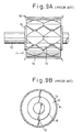
- Figs. 9A and 9B show a further construction of a typical surface-mounted magnet type rotor for a conventional synchronous electric motor, in which permanent magnets are held securely on the rotor core solely by the adhesive strength of an adhesive.
- Figs. 9A and 9B are a front view and a side view, respectively, of the surface-mounted magnet type rotor. Referring to Figs.
- a rotor 11 supported for rotation within a stator 10 with a gap between the outer circumference thereof and the cylindrical inner circumference of the stator 10 comprises a rotor shaft 12, a cylindrical rotor core 13 fixedly mounted on the rotor shaft 12, a plurality of permanent magnets 14 having the shape of a modified octagon attached by adhesive at their bottom surface to the outer circumference of the cylindrical rotor core 13, ends of the rotor core 13 to hold the rotor core in place on the rotor shaft 12.
- the permanent magnets 14 of this typical surface-mounted magnet type rotor are secured to the rotor core 13 solely by the adhesive strength of the adhesive, which is not a sufficiently effective measure to prevent the separation of the permanent magnets 14 from the rotor core 13.
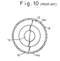
- Fig. 10 is a side view, corresponding to Fig. 9B, of a rotor having permanent magnets partly sunk in recesses formed in the outer circumference of a rotor core.
- the construction shown in Fig. 10 is more effective in preventing separation than the construction shown in Fig. 9B.
- Fig. 10 is more effective in preventing separation than the construction shown in Fig. 9B.
- a rotor core 13 is provided in its outer circumference with axial dovetail grooves 16, and permanent magnets 14a having the shape of a curved plate and formed in a shape complementary to that of the dovetail grooves 16 and having an upper surface, a lower surface of a width greater than that of the upper surface, and side surfaces extending outward so as to approach each other and inserted in the dovetail grooves 16.
- the permanent magnets 14a need necessarily to be inserted axially of the rotor core 13 in the dovetail grooves 16 and positioned in place with respect to the axial direction.
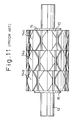
- the rotor when as shwon in Fig. 11, the rotor is provided with a plurality of permanent magnets 14a divided into a plurality of groups (three groups in Fig. 11) and the groups of permanent magnets 14a are arranged respectively in a plurality of axial divisions (three axial divisions in Fig. 11) on the outer circumference of the rotor core 13 with the angular position of the permanent magnets 14a of each group shifted relative to that of the permanent magnets 14a of other groups to suppress torque ripple, it is impossible to insert the permanent magnets 14a of the middle group axially in the corresponding dovetail grooves 16 of the rotor core 13.
- a principal object of the present invention is to solve the foregoing problems in the rotor of the conventional synchronous rotary machine, particularly, in the surface-mounted magnet type rotor.
- a further object of the present invention is to provide a surface-mounted magnet type rotor comprising a rotor core, and permanent magnets attached substantially to the outer circumference of the rotor core, such that, on the one hand they are fixedly attached to the rotor core and on the other hand a very effective cooling of the rotor core is made possible.
- Another object of the present invention is to provide a surface-mounted magnet type rotor comprising a rotor core, and permanent magnets attached substantially to the outer circumference of the rotor core, capable of being assembled by assembling processes as simple as those for assembling the conventional surface-mounted magnet type rotor without requiring additional assembling work, and having a construction having a mechanical fastening strength capable of securely holding the permanent magnets on the rotor core so that the permanent magnets are not separated from the surface of the rotor core by the centrifugal force generated by the rotation of the rotor and the magnetic attraction resulting from the magnetic interactions of the stator magnetic field created by the stator, and the permanent magnets and that additionally a very effective cooling of the rotor core 13 is achieved.
- a further object of the present invention is to provide a method of fabricating a surface-mounted magnet type rotor for a synchronous rotary machine, having a rotor core provided with recesses in its outer circumference, and permanent magnets fitted in the recesses of the rotor core by radially fitting the permanent magnets in the recesses of the rotor core like tiling a surface.
- each permanent magnet when fabricating the surface-mounted magnet type rotor for a synchronous rotary machine, each permanent magnet is inserted radially in the recess formed in the substantially cylindrical surface of the rotor core.
- Each recess and each permanent magnet are formed so that wedging spaces are formed on the opposite sides of the permanent magnet between the side faces of the permanent magnet and walls demarcating the recess, and wedge-like layers of an adhesive are formed in the wedging spaces to secure the permanent magnet in place against the resultant of the centrifugal force generated by the rotation of the rotor and the magnetic attraction resulting from magnetic interactions of magnetic fields created by the stator, and the permanent magnet, that tends to separate the permanent magnet from the rotor core.
- a rotor 20 for a synchronous rotary machine in a first embodiment according to the present invention, similarly to the conventional rotor, is a motor element supported for rotation inside a stator 10 with a gap between the outer circumference thereof and the cylindrical inner circumference of the stator 10.
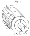
- the rotor 20 comprises a rotor shaft 22, a substantially cylindrical rotor core 23 adhesively fixed or fastened with a wedge to the rotor shaft 22, and a plurality of permanent magnets 25 fitted respectively in recesses 26 formed in the outer circumference of the rotor core 23.
- Each of the permanent magnets 25 is formed in the shape of a curved piece of plate and has a lower surface 25a curved in a curvature corresponding to that of the outer circumference of the rotor core 23, an upper surface having a radially outward convex shape determined on the basis of design conditions determined taking into consideration conditions for magnetic interactions, axially opposite end faces 24 parallel to a plane perpendicular to the axis of rotation of the rotor 20, and opposite, inclined side faces 27a and 27b diverging from each other toward the lower surface 25a so as to extend opposite to the side faces of the recess 26 with gaps therebetween, respectively.
- the inclined side faces 27a and 27b extend perpendicularly to the opposite end faces 24.
- the rotor 20 similarly to the conventional rotor, is provided with end plates 28 attached to the axially opposite ends of the rotor core 23.
- each permanent magnet 25 is attached to the rotor core 23 by adhesively joining the lower surface 25a thereof to the bottom surface of the recess 26, adhesively joining the inclined side faces 27a and 27b thereof to the side faces of the recess 26 facing thereto with an adhesive and hardening the adhesive filling up gaps between the inclined side faces 27a and 27b and the side faces of the recess 26 in wedge-like layers 30 of the adhesive.
- the wedge effect of the wedge-like layers 30 of adhesive holds each permanent magnet 25 securely in a recess 26 so that each permanent magnet 25 will not be separated from the rotor core 23 by the resultant of centrifugal force that acts radially outward on the permanent magnet when the rotor 20 is rotated at a high rotating speed and radial magnetic attraction resulting from interactions of a rotating magnetic field created by the stator 10, and each permanent magnet 25.
- each recess 26 is a dovetail groove expanding radially inward and having a curved bottom surface 26a having the shape of an arc of a circle, and opposite, inclined side faces 26b and 26c diverging from each other radially inward.
- the inclined side faces 26b and 26c are complementary respectively to the inclined side faces 27a and 27b of the permanent magnet 25, and the inclined side faces are the opposite side faces of a dovetail groove that enables the permanent magnet 25 to be advanced radially toward the bottom surface 26a of the recess 26 of the rotor core 23 as indicated by the arrow P in Fig. 2 when fitting the permanent magnet 25 in the recess 26 and forms minute gaps between the inclined side faces 27a and 27b of the permanent magnet 25 and the corresponding inclined side faces 26b and 26c of the recess 26 to enable the permanent magnet 25 to be removed from the recess 26 when the permanent magnet 25 is pulled radially outward in a direction opposite the direction of the arrow P.
- the lower surface 25a and the inclined side faces 27a and 27b thereof are coated with an adhesive.
- the permanent magnet 25 is seated on the bottom surface 26a of the recess 26, the minute gaps are substantially fully filled up with the adhesive.
- the adhesive filling the minute gaps is hardened to form the wedge-like layers 30.
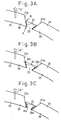
- the dimensional relation between the permanent magnet 25 and the recess 26 so that the distance between the edges A along which the inclined side faces 27a and 27b of the permanent magnet 25 intersect the lower surface 25a of the same, respectively, is slightly smaller than the distance between the edges B of the recess 26, and the edges A of the permanent magnet 25 graze the edges B of the recess 26 when the wedge-like layers 30 are not formed and permanent magnet 25 is pulled in the direction of the arrow R.
- the wedge-like layers 30 exert the wedging effect on the permanent magnet 25 even if a large separating force resulting from the centrifugal force generated by the rotation of the rotor and the magnetic attraction acts on the permanent magnet and a large compressive force acts accordingly on the wedge-like layers 30 of adhesive, unless the wedge-like layers 30 are crushed completely and pushed completely out of the gaps.
- the wedging effect of the wedge-like layers 30 restrains the permanent magnet from being separated from the rotor core 23.
- the inclination of the inclined side faces 27a and 27b of the permanent magnet 25 and the inclination of the corresponding inclined side faces 26b and 26c of the recess 26 of the rotor core 23 are greater than those of the permanent magnet 25 and the recess 26 shown in Fig. 3A to enhance the wedging effect of the wedge-like layers 30 of the adhesive.
- the wedging effect of the wedge-like layers 30 of the adhesive on restraining the permanent magnet 25 from being separated from the rotor core 23 is enhanced by partially recessing the inclined side faces 26b and 26c of the recess 26 of the rotor core 23 to increase the thickness of the wedge-like layers 30 of the adhesive.
- Fig. 4 shows a rotor 20 for a synchronous rotary machine, in a second embodiment according to the present invention.
- the rotor 20 in the second embodiment differs from the rotor 20 in the first embodiment in that recesses 26 are formed in the circumference of a rotor core 23 so as to extend at a fixed helix angle ⁇ .
- the rotor 20 in the second embodiment is similar to the rotor 20 in the first embodiment in that the recesses 26 are formed substantially straight along the axis of rotation in the outer circumference of the rotor core 23, the recesses 26 are arranged at angular intervals, and the recesses 26 have the shape of a dovetail groove expanding radially inward.
- each permanent magnet 25 to be radially fitted in the recesses 26 like tiling a surface are formed so as to extend at a helix angle ⁇ .
- the inclined side faces 27a and 27b similarly to those of the first embodiment, are coated with an adhesive, and wedge-like layers 30 are formed to secure the permanent magnet 25 firmly in the recess 26 to restrain the permanent magnet 25 from being separated from the rotor core 23.
- the permanent magnets 25 are arranged on the rotor core 23 in an axially skew arrangement skewing at a helix angle ⁇ to the axis of the rotor core 23 to suppress torque ripple attributable to slots formed in the inner circumference of the stator 10 to hold coils therein.
- the permanent magnets 25 can be radially fitted in the recesses 26 like tiling a surface.
- Fig. 5 is a perspective view of the rotor core 23 provided with the recesses 26 skewed at a helix angle ⁇ to the axis of rotation of the rotor core 23.
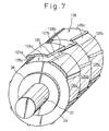
- Figs. 6 and 7 show a rotor for a synchronous rotary machine, in a third embodiment according to the present invention.
- recesses 126 are formed in a plurality of axial recess divisions (three recess divisions in this embodiment) 126a to 126c of a short axial length.
- the recesses 126 in each of the recess divisions 126a, 126b and 126c, similarly to the recesses in the second embodiment, are arranged in a skew arrangement skewing at a helix angle ⁇ to the axis of rotation of the rotor 20 and have the shape of a dovetail groove.
- phase angles of the respective recesses 126 of the adjacent recess groups i.e., the recess division 126a and 126b, and the recess divisions 126b and 126c, have a fixed phase angle difference ⁇ to provide permanent magnets 125 fitted in the respective recesses of the recess divisions 126a, 126b and 126c, with a torque ripple suppressing effect.
- the phase angle difference ⁇ is determined taking into consideration the degree of the torque ripple included in the torque produced by the magnetic interaction of a rotating magnetic field created by the stator and the permanent magnets 125.
- the permanent magnets 125 when assembling the permanent magnets 125 and the rotor core 23, the permanent magnets 125 can be radially fitted in the recesses 126 of the recess divisions 126a, 126b and 126c like tiling a surface.
- the permanent magnets 125 can be radially fitted in the recesses 126 of the recess divisions 126a, 126b and 126c in the direction of the arrow P like tiling a surface even though the phases of the respective recesses 126 of the adjacent recess 126a, 126b and 126c are shifted relative to each other by the phase angle difference ⁇ , which is impossible in assembling the conventional rotor in which the permanent magnets are inserted axially in the recesses.
- the adhesive filling up gaps between the inclined side faces 127a and 127b of each permanent magnet 125 and the corresponding inclined side faces 128a and 128b of each of the recesses 126 of the recess divisions 126a to 126c forms wedge-like layers 130 (Fig. 6) when hardened, and the strong wedging function of the wedge-like layers 130 restrains the permanent magnets 125 from being separated from the rotor core 23 by the centrifugal force generated by the rotation of the rotor 20 and the magnetic attraction.
- the effect of the arrangement of the permanent magnets 125 in the third embodiment, in which the phase of the recesses 126 of each of the recess divisions 126a, 126b and 126c are shifted by the phase angle difference ⁇ relative to that of the recesses 126 of the adjacent recess divisions, on the suppression of torque ripple can be produced, for example, by dividing the axial recesses 26 of the rotor core 23 in the first embodiment into sectional axial recesses, dividing the sectional axial recesses into a plurality of axial recess divisions and shifting the phase of the sectional axial recesses of each of the plurality of axial recess divisions relative to that of the sectional axial recesses of the adjacent axial recess divisions by a phase angle difference ⁇ .
- a rotor provided with permanent magnets arranged in such an arrangement is shown in Fig. 8.
- axial recesses 26 are divided into sectional axial recesses of the three axial recess divisions, and the phase of the sectional axial recesses of each axial recess division is shifted by a phase angle difference ⁇ relative to that of the sectional axial recess of the adjacent axial recess divisions.
- the permanent magnets 25 can be radially fitted in the sectional axial recesses 26 like tiling a surface similarly to those of the foregoing embodiments.
- the permanent magnets employed in the foregoing embodiments have quadrilateral shapes, respectively, in a plan view. It will be easily understood by a person with ordinary skill in the art to which the present invention pertains that the permanent magnets may be of any suitable polygonal shape, such as the octagonal permanent magnets employed in the conventional rotor for a synchronous motor, provided that each permanent magnet has side surfaces that are able to form spaces for forming wedge-like layers therein by filling up the spaces with an adhesive and hardening the adhesive filling up the spaces together with the corresponding side faces of a recess when the permanent magnet is fitted radially in the recess like tiling a surface. Accordingly, permanent magnets applicable to the rotor of the present invention are not limited to the foregoing quadrilateral permanent magnets.
- a rotor for a synchronous rotary machine particularly, a surface-mounted magnet type rotor comprising a substantially cylindrical rotor core and permanent magnets attached to the outer circumference of the rotor core, has a construction that enables the assembly of the rotor core and the permanent magnets by radially fitting the permanent magnets in recesses resembling a dovetail groove like tiling a surface, and wedge-like layers of adhesive formed by filling up spaces formed between the side faces of the permanent magnet and the corresponding side faces of the recess and hardening the adhesive filling up the spaces, restrains the permanent magnets from being separated from the rotor core by the centrifugal force generated by the rotation of the rotor and the magnetic attraction, highly effectively.
- the construction of the rotor of the present invention enhances the mechanical permanent magnet anchoring force against the force tending to separate the surface-mounted permanent magnets from the rotor core remarkably and the life and reliability of the synchronous rotary machine incorporating the rotor of the present invention are improved accordingly.
- the permanent magnets of the rotor are arranged in a skew arrangement or in an offset arrangement, in which the phase of the permanent magnets fitted in the recesses of one of a plurality of recess divisions is shifted relative to that of the permanent magnets fitted in the recesses of the adjacent recess divisions, on the outer circumference of the rotor core of the rotor, the permanent magnets can be attached to the outer circumference of the rotor core by radially fitting the permanent magnets in the recesses when assembling the rotor.
- the rotor of the present invention can be assembled by a rotor assembling method that does not require any work in addition to that required by the rotor assembling method for assembling the conventional surface-mounted magnet type rotor and is rather simpler than the rotor assembling method for assembling the conventional surface-mounted magnet type rotor.
Landscapes
- Engineering & Computer Science (AREA)
- Power Engineering (AREA)
- Manufacturing & Machinery (AREA)
- Permanent Field Magnets Of Synchronous Machinery (AREA)
- Iron Core Of Rotating Electric Machines (AREA)
Claims (7)
- Rotor (20) für eine Synchronmaschine, der drehbar innerhalb eines Stators (10) gelagert ist und einen im wesentlichen zylindrischen Rotorkern aufweist, mit einer äußeren Umfangsfläche, an der eine Vielzahl von Permanentmagnetstücken befestigt ist, wobeijedes der Permanentmagnetstücke (25) eine polygonale Gestalt aufweist mit ebenen, axial entgegengesetzten Endflächen (24), parallel zu einer Ebene senkrecht zu der Drehachse des Rotors (20), mit Seitenflächen (27a, 27b), deren jede die entgegengesetzten Endflächen (24) schneiden, mit gekrümmten oberen und unteren Oberflächen (25a, 25b), die so ausgebildet sind, daß sie eine Krümmung aufweisen, die im wesentlichen übereinstimmt mit derjenigen der äußeren Umfangsfläche des zylindrischen Rotorkerns (23), wobei die untere Oberfläche (25a) eine größere Breite aufweist als die obere Oberfläche (25b), so daß die Seitenflächen (27a, 27b), welche die obere und untere Oberfläche (25a, 25b) verbinden, geneigt sind, derart, daß sie zu der unteren Oberfläche (25a) hin divergieren,wobei der zylindrische Rotorkern (23) mit einer Oberfläche versehen ist, die mit einer Vielzahl von im wesentlichen schwalbenschwanzförmigen Vertiefungen (26) ausgebildet ist, deren jede eine axiale und zylindrisch sich erstreckende Bodenfläche (26a) und einander gegenüberliegende geneigte Seitenflächen (26b, 26c) aufweist, welche hin zu der Bodenfläche (26a) divergieren, derart, daß Zwischenräume gebildet werden zwischen den geneigten Seitenflächen (26b, 26c) der Vertiefung (26) und den geneigten Seitenflächen (27a, 27b) der Permanentmagnetstücke (25), wenn die untere Oberfläche (25a) des Permanentmagnetstücks (25) radial in die Vertiefung (26) eingesetzt ist, wobei die Vielzahl der schwalbenschwanzförmigen Vertiefungen (26) in Umfangsrichtung in vorgegebenen Winkelintervallen angeordnet sind,dadurch gekennzeichnet, daß:die Permanentmagnetstücke (25) derart in den Vertiefungen (26) gehalten sind, daß ein oberer Bereich jedes Permanentmagnetstücks (25) oberhalb der oberen zylindrischen Umfangsfläche des Rotorkerns (23) angeordnet ist; unddaß die zwischen den geneigten Seitenflächen (27a, 27b) jedes Permanentmagnetstücks (25) und den geneigten Seitenflächen (26b, 26c) jeder Vertiefung (26) gebildeten Zwischenräume mit einem Klebematerial versehen sind zur Ausbildung von keilförmigen Schichten (30) des Klebematerials zwischen den geneigten Seitenflächen (27a, 27b) des Permanentmaggnetstücks (25) und den geneigten Seitenflächen (26b, 26c) der Vertiefungen (26), so daß die keilförmigen Schichten (30) des Klebstoffs das Permanentmagnetstück (25) sicher in der Vertiefung (26) halten, um hierdurch eine Ablösung des Permanentmagnetstücks (25) von dem Rotorkern (23) zu verhindern.
- Rotor (20) für eine Synchronmaschine nach Anspruch 1, bei dem jede der Vielzahl von schwalbenschwanzförmigen Vertiefungen (26) des Rotorkerns (23) eine sich durchgängig parallel zu der Drehachse des Rotors (20) erstreckende Nut ist, und bei dem wenigstens eines der Permanentmagnetstücke (25) in diese durchgängige Nut eingesetzt ist.
- Rotor (20) für eine Synchronmaschine nach Anspruch 1, bei dem die schwalbenschwanzförmige Vertiefung (26) des Rotorkerns (23) eine sich durchgängig unter einem diagonalen Winkel (θ) in bezug auf die Drehachse des Rotors (20) erstrekkende Nut ist, und bei dem eine Vielzahl der Permanentmagnetstücke (25) in die diagonal sich erstreckende durchgängige Nut eingesetzt sind.
- Rotor (20) für eine Synchronmaschine nach Anspruch 1, bei dem jede der Vielzahl der schwalbenschwanzförmigen Vertiefungen (26) des Rotorkerns (23) eine Vielzahl von geraden Vertiefungen (126a, 126b, 126c) aufweist, deren jede eine vorbestimmte Länge entlang eines vorgegebenen diagonalen Winkels (θ) in bezug auf die Drehachse des Rotors (20) aufweist, wobei die Vielzahl der unterteilten geraden Vertiefungen (126a, 126b, 126c) in Umfangsrichtung relativ zueinander um einen vorgegebenen Winkel (β) versetzt sind, und bei dem eine Vielzahl der Permanentmagnetstücke (25) jeweils in die Vielzahl der unterteilten geraden Vertiefungen (126a, 126b, 126c) der schwalbenschwanzförmigen Vertiefung (126) eingefügt sind.
- Rotor (20) für eine Synchronmaschine nach Anspruch 1, bei dem jeder der Vielzahl von schwalbenschwanzförmigen Vertiefungen (126) des Rotorkerns (23) eine Vielzahl von unterteilten geraden Vertiefungen (26) einschließt, die sich mit einer vorgegebenen Länge parallel zur Drehachse des Rotors (20) erstrecken, wobei die Vielzahl der unterteilten geraden Vertiefungen (26) in Umfangsrichtung relativ zueinander unter einem vorgegebenen Winkel (γ) versetzt sind, und bei dem eine Vielzahl der Permanentmagnetstücke (25) jeweils in die Vielzahl der unterteilten geraden Vertiefungen (26) jeder schwalbenschwanzförmigen Vertiefung (26) eingefügt sind.
- Verfahren zur Herstellung eines Rotors (20) für eine Synchronmaschine, der drehbar innerhalb eines Stators (10) gelagert ist und einen im wesentlichen zylindrischen Rotorkern aufweist, mit einer äußeren Umfangsfläche, an der eine Vielzahl von Permanentmagnetstücken befestigt ist, umfassend die Schritte:Ausbildung der Permanentmagnetstücke (25) als im wesentlichen polygonale Platte mit ebenen, axial entgegengesetzten Endflächen (24), parallel zu einer Ebene senkrecht zu der Drehachse des Rotors (20), mit Seitenflächen (27a, 27b), deren jede die entgegengesetzten Endflächen (24) schneiden, mit gekrümmten oberen und unteren Oberflächen (25a, 25b), die so ausgebildet sind, daß sie eine Krümmung aufweisen, die im wesentlichen übereinstimmt mit derjenigen der äußeren Umfangsfläche des zylindrischen Rotorkerns (23), wobei die untere Oberfläche (25a) eine größere Breite aufweist als die obere Oberfläche (25b), so daß die Seitenflächen (27a, 27b), welche die obere und untere Oberfläche (25a, 25b) verbinden, geneigt sind, derart, daß sie zu der unteren Oberfläche (25a) hin divergieren,Ausbilden einer Vielzahl von schwalbenschwanzförmigen Vertiefungen (26) in der äußeren Umfangsfläche des Rotorkerns in einem vorgegebenen Winkelintervall in Umfangsrichtung, deren jede eine axiale und zylindrisch sich erstreckende Bodenfläche (26a) und einander gegenüberliegende geneigte Seitenflächen (26b, 26c) aufweist, welche hin zu der Bodenfläche (26a) divergieren, derart, daß Zwischenräume gebildet werden zwischen den geneigten Seitenflächen (26b, 26c) der Vertiefung (26) und den geneigten Seitenflächen (27a, 27b) der Permanentmagnetstücke (25), wenn die untere Oberfläche (25a) des Permanentmagnetstücks (25) radial in die Vertiefung (26) eingesetzt ist,Einspritzen eines Klebstoffs in die Zwischräume, die zwischen den geneigten Seitenflächen (26a, 26b) der Vertiefungen (26) und den mit diesen korrespondierenden geneigten Seitenflächen (27a, 27b) der Permanentmagnetstücke (25) ausgebildet sind, nachdem die Permanentmagnetstücke (25) radial in die Vertiefungen (26) des Rotorkerns (23) eingefügt wurden, um die Zwischenräume mit dem Klebstoff zu füllen,gekennzeichnet durch die Schritte:
Einfügen der Permanentmagnetstücke (25) in die Vertiefung (26) derart, daß ein oberer Teil der Permanentmagnetstücke (25) oberhalb der äußeren zylindrischen Umfangsfläche des Rotorkerns (23) angeordnet ist und Härten der mit Klebstoff gefüllten Zwischenräume zur Ausbildung von keilförmigen Schichten (30), die eine Ablösung der Permanentmagnetstücke (25) von der äußeren Umfangsfläche des Rotorkerns (23) verhindern. - Verfahren nach Anspruch 6, bei dem die untere Oberfläche (25a) des Permanentmagneten (25) mit einem Klebstoff beschichtet ist, um eine filmartige Schicht des Klebstoffs zwischen der unteren Oberfläche (25a) des Permanentmagnetstücks (25) und der Bodenfläche (26a) der Vertiefung (26) des Rotorkerns (23) auszubilden, und bei dem die filmartige Klebstoffschicht gehärtet ist, um eine harte Klebstoffschicht zwischen der unteren Oberfläche (25a) des Permanentmagnetstücks (25) und der Bodenfläche (26a) der Vertiefung (26) auszubilden.
Applications Claiming Priority (3)
| Application Number | Priority Date | Filing Date | Title |
|---|---|---|---|
| JP3316225A JPH05161287A (ja) | 1991-11-29 | 1991-11-29 | 同期機のロータ |
| JP316225/91 | 1991-11-29 | ||
| PCT/JP1992/001368 WO1993011596A1 (en) | 1991-11-29 | 1992-10-21 | Rotor of synchronous rotating machine |
Publications (3)
| Publication Number | Publication Date |
|---|---|
| EP0569594A1 EP0569594A1 (de) | 1993-11-18 |
| EP0569594A4 EP0569594A4 (de) | 1994-02-16 |
| EP0569594B1 true EP0569594B1 (de) | 1997-01-08 |
Family
ID=18074703
Family Applications (1)
| Application Number | Title | Priority Date | Filing Date |
|---|---|---|---|
| EP92921819A Expired - Lifetime EP0569594B1 (de) | 1991-11-29 | 1992-10-21 | Rotor synchroner drehmaschinen |
Country Status (5)
| Country | Link |
|---|---|
| EP (1) | EP0569594B1 (de) |
| JP (1) | JPH05161287A (de) |
| KR (1) | KR0132516B1 (de) |
| DE (1) | DE69216587T2 (de) |
| WO (1) | WO1993011596A1 (de) |
Cited By (3)
| Publication number | Priority date | Publication date | Assignee | Title |
|---|---|---|---|---|
| DE102010043970A1 (de) | 2010-11-16 | 2012-05-16 | Robert Bosch Gmbh | Elektrische Maschine für einen Lenkantrieb |
| US9257874B2 (en) | 2011-04-02 | 2016-02-09 | Nidec Corporation | Rotor unit, rotating electrical machine, and method of manufacturing rotor unit |
| US11515745B2 (en) * | 2018-06-14 | 2022-11-29 | Abb Schweiz Ag | Rotor with surface mounted magnets |
Families Citing this family (40)
| Publication number | Priority date | Publication date | Assignee | Title |
|---|---|---|---|---|
| EP0678967A1 (de) * | 1994-04-18 | 1995-10-25 | General Electric Company | Läufer für einen Permanentmagnetmotor |
| DE19542551A1 (de) * | 1995-11-15 | 1997-05-22 | Oswald Elektromotoren Gmbh | Synchronmotor |
| BR9702802A (pt) * | 1997-08-28 | 2000-02-15 | Brasil Compressores Sa | Rotor para motor elétrico. |
| US6812609B2 (en) | 1998-10-21 | 2004-11-02 | Werner Anwander | Electric machine having electric coils and permanent magnets |
| DE19848503A1 (de) * | 1998-10-21 | 2000-04-27 | Werner Anwander | Elektrische Maschine |
| JP4089072B2 (ja) * | 1998-10-23 | 2008-05-21 | 三菱電機株式会社 | 永久磁石埋込み形モータ |
| JP2001078376A (ja) * | 1999-09-03 | 2001-03-23 | Kokusan Denki Co Ltd | 回転電機用磁石回転子 |
| KR20010054562A (ko) * | 1999-12-07 | 2001-07-02 | 송재인 | 직류 전동기의 회전자 |
| KR100655994B1 (ko) * | 1999-12-29 | 2006-12-08 | 두산인프라코어 주식회사 | 서보 모터용 로터의 조립구조 |
| DE10126730A1 (de) * | 2001-05-31 | 2003-01-02 | Sachsenwerk Gmbh | Rotierende oder lineare elektrische Maschine mit Permanentmagneterregung insbesondere mit vorgefertigten Permanentmagneten |
| DE10233900A1 (de) * | 2002-07-25 | 2004-02-19 | Vacuumschmelze Gmbh & Co. Kg | Permanentmagnetanordnung für ebene Linearantriebe |
| DE10240580A1 (de) * | 2002-08-29 | 2004-03-11 | Claas Industrietechnik Gmbh | Rotor eines elektrischen Antriebs und Verfahren zu seiner Herstellung |
| US6984908B2 (en) * | 2003-08-26 | 2006-01-10 | Deere & Company | Permanent magnet motor |
| DE102004045939B4 (de) * | 2004-09-22 | 2010-10-07 | Siemens Ag | Permanenterregte Synchronmaschine mit Unterdrückungsmitteln zur Verbesserung der Drehmomentwelligkeit |
| JP4882293B2 (ja) * | 2005-07-13 | 2012-02-22 | シンフォニアテクノロジー株式会社 | 永久磁石同期回転電機のロータの製造方法 |
| DE102005044218A1 (de) * | 2005-09-15 | 2007-03-22 | Temic Automotive Electric Motors Gmbh | Elektromotor |
| DE102005048546A1 (de) * | 2005-10-11 | 2007-04-12 | Robert Bosch Gmbh | Rotor für eine elektrische Maschine |
| JP4854001B2 (ja) * | 2005-11-29 | 2012-01-11 | 三菱重工プラスチックテクノロジー株式会社 | 射出成形機用モータ、埋め込み磁石型モータの回転子 |
| DE102006004537A1 (de) * | 2006-02-01 | 2007-08-02 | Volkswagen Ag | Elektrische Maschine |
| DE102006033718B4 (de) * | 2006-07-20 | 2017-10-19 | Siemens Aktiengesellschaft | Elektrische Maschine mit schräg verlaufenden Magnetpolgrenzen |
| JP2010051150A (ja) * | 2008-08-25 | 2010-03-04 | Mitsuba Corp | ブラシレスモータ |
| DE102008063045A1 (de) * | 2008-12-23 | 2010-07-01 | Aerodyn Energiesysteme Gmbh | Synchronmaschine |
| JP2010178442A (ja) * | 2009-01-28 | 2010-08-12 | Hitachi Ltd | 外転型永久磁石回転電機およびそれを用いたエレベータ装置 |
| FI20090115A0 (fi) * | 2009-03-25 | 2009-03-25 | Abb Oy | Kestomagnetoitu sähkökone ja kestomagneetti sähkökonetta varten |
| IT1397689B1 (it) * | 2009-10-22 | 2013-01-24 | Sicor Spa | Motore elettrico con rotore a magneti permanenti |
| JP5842365B2 (ja) * | 2011-04-02 | 2016-01-13 | 日本電産株式会社 | ロータユニット、回転電機、およびロータユニットの製造方法 |
| CN102364823B (zh) * | 2011-09-23 | 2013-05-08 | 宁波沃伏龙机电有限公司 | 转子 |
| JP5496255B2 (ja) * | 2012-05-31 | 2014-05-21 | 三菱電機株式会社 | 磁石式回転電機の回転子の製造方法およびその製造装置 |
| JPWO2014002181A1 (ja) * | 2012-06-26 | 2016-05-26 | 三菱電機株式会社 | 永久磁石式回転電機、及びその製造方法 |
| CN102780294B (zh) * | 2012-08-22 | 2015-04-15 | 南车株洲电机有限公司 | 一种永磁电机 |
| KR102008839B1 (ko) * | 2012-09-27 | 2019-08-08 | 엘지이노텍 주식회사 | 모터 |
| CN102931744B (zh) * | 2012-11-27 | 2014-12-31 | 南京埃斯顿自动控制技术有限公司 | 一种表面式永磁同步直驱电机转子 |
| EP3382867A1 (de) * | 2013-04-09 | 2018-10-03 | Mitsubishi Electric Corporation | Dauerhafte magnettyp motor und elektrische servolenkungsanlage |
| JP6255861B2 (ja) * | 2013-10-02 | 2018-01-10 | 株式会社ジェイテクト | ロータおよび電動モータ |
| DE102013220562B4 (de) * | 2013-10-11 | 2024-12-19 | Robert Bosch Gmbh | Baugruppe für eine elektrische Maschine, Verfahren zur Herstellung einer Baugruppe und elektrische Maschine mit einer Baugruppe |
| DE102014201152A1 (de) * | 2014-01-22 | 2015-07-23 | Volkswagen Aktiengesellschaft | Permanentmagnetelement und Rotor mit einem solchen |
| KR102458635B1 (ko) * | 2015-09-14 | 2022-10-25 | 엘지이노텍 주식회사 | 로터 및 이를 포함하는 모터 |
| US10587180B2 (en) | 2016-05-13 | 2020-03-10 | Otis Elevator Company | Magnetic elevator drive member and method of manufacture |
| JP7169170B2 (ja) * | 2018-11-15 | 2022-11-10 | 株式会社ミツバ | ロータ、モータ及びブラシレスモータ |
| JP2021058040A (ja) * | 2019-10-01 | 2021-04-08 | 東芝産業機器システム株式会社 | Spm形回転電機の回転子 |
Family Cites Families (13)
| Publication number | Priority date | Publication date | Assignee | Title |
|---|---|---|---|---|
| JPS5096807A (de) * | 1973-12-27 | 1975-08-01 | ||
| JPS5752783U (de) * | 1980-09-12 | 1982-03-26 | ||
| JPS5752784U (de) * | 1980-09-12 | 1982-03-26 | ||
| JPS5829359A (ja) * | 1981-08-12 | 1983-02-21 | Hitachi Ltd | 永久磁石付回転子 |
| JPS60125149A (ja) * | 1983-12-09 | 1985-07-04 | Toshiba Corp | 回転電機の回転子 |
| JPS6117876U (ja) * | 1984-07-05 | 1986-02-01 | 株式会社東芝 | 永久磁石回転電機 |
| JPH0424767Y2 (de) * | 1985-04-26 | 1992-06-11 | ||
| JPS61202166U (de) * | 1985-06-07 | 1986-12-18 | ||
| US4642502A (en) * | 1986-04-24 | 1987-02-10 | General Motors Corporation | Dynamoelectric machine with permanent magnet and magnet mounting surface arrangement |
| JPS63120568U (de) * | 1987-01-28 | 1988-08-04 | ||
| JPS63213442A (ja) * | 1987-02-27 | 1988-09-06 | Aichi Electric Co Ltd | 永久磁石付回転子 |
| GB2217924B (en) * | 1988-04-25 | 1992-10-07 | Matsushita Electric Works Ltd | Permanent magnet rotor |
| JPH0295150A (ja) * | 1988-09-27 | 1990-04-05 | Matsushita Electric Works Ltd | 永久磁石回転子 |
-
1991
- 1991-11-29 JP JP3316225A patent/JPH05161287A/ja active Pending
-
1992
- 1992-10-21 WO PCT/JP1992/001368 patent/WO1993011596A1/ja active IP Right Grant
- 1992-10-21 EP EP92921819A patent/EP0569594B1/de not_active Expired - Lifetime
- 1992-10-21 KR KR1019930702188A patent/KR0132516B1/ko not_active IP Right Cessation
- 1992-10-21 DE DE69216587T patent/DE69216587T2/de not_active Expired - Fee Related
Cited By (4)
| Publication number | Priority date | Publication date | Assignee | Title |
|---|---|---|---|---|
| DE102010043970A1 (de) | 2010-11-16 | 2012-05-16 | Robert Bosch Gmbh | Elektrische Maschine für einen Lenkantrieb |
| WO2012065778A2 (de) | 2010-11-16 | 2012-05-24 | Robert Bosch Gmbh | Elektrische maschine für einen lenkantrieb |
| US9257874B2 (en) | 2011-04-02 | 2016-02-09 | Nidec Corporation | Rotor unit, rotating electrical machine, and method of manufacturing rotor unit |
| US11515745B2 (en) * | 2018-06-14 | 2022-11-29 | Abb Schweiz Ag | Rotor with surface mounted magnets |
Also Published As
| Publication number | Publication date |
|---|---|
| DE69216587D1 (de) | 1997-02-20 |
| WO1993011596A1 (en) | 1993-06-10 |
| DE69216587T2 (de) | 1997-07-10 |
| KR930703729A (ko) | 1993-11-30 |
| EP0569594A1 (de) | 1993-11-18 |
| EP0569594A4 (de) | 1994-02-16 |
| JPH05161287A (ja) | 1993-06-25 |
| KR0132516B1 (ko) | 1998-04-20 |
Similar Documents
| Publication | Publication Date | Title |
|---|---|---|
| EP0569594B1 (de) | Rotor synchroner drehmaschinen | |
| US5397951A (en) | Rotor for a synchronous rotary machine | |
| US5097166A (en) | Rotor lamination for an AC permanent magnet synchronous motor | |
| US7057322B2 (en) | Rotor for reluctance type rotating machine | |
| EP0140981A1 (de) | Rotor mit permanentem magnetfeld | |
| EP0582721B1 (de) | Rotor eines synchronmotors | |
| EP3338343B1 (de) | Motor | |
| EP2037556B1 (de) | Elektrische Maschine mit einer Anordnung der Permanentmagneten, um das Pulsieren des Drehmoments zu reduzieren | |
| EP1990895B1 (de) | Belastungsverteilende Permamentmagnet-Rotorgeometrie für elektrische Maschinen | |
| US4642502A (en) | Dynamoelectric machine with permanent magnet and magnet mounting surface arrangement | |
| US7768171B2 (en) | Rotor of permanent magnet rotating electric machine | |
| US20040189136A1 (en) | Stator design for permanent magnet motor with combination slot wedge and tooth locator | |
| EP2826134B1 (de) | Rotor mit verdrehsicherung für eine mehrpolige struktur | |
| WO1988005617A1 (en) | Structure of rotor of synchronizing ac servo motor | |
| EP2485371A2 (de) | Rotierende elektrische Maschine | |
| JPH071990B2 (ja) | 永久磁石式回転電機 | |
| JPH08107639A (ja) | 永久磁石形同期回転電機のロータ | |
| JP2006333656A (ja) | 回転電機の回転子及びそれを用いた回転電機 | |
| JP2012080607A (ja) | 回転電機のロータ | |
| JP6631794B2 (ja) | ロータおよびモータ | |
| JPH05199684A (ja) | 同期機のロータとその製造方法 | |
| KR920000500B1 (ko) | 동기 전동기의 로우터 구조 | |
| TWI643430B (zh) | 轉子及旋轉電機 | |
| KR100548765B1 (ko) | 영구자석 회전자 | |
| JP2004222467A (ja) | 埋込磁石型モータ |
Legal Events
| Date | Code | Title | Description |
|---|---|---|---|
| PUAI | Public reference made under article 153(3) epc to a published international application that has entered the european phase |
Free format text: ORIGINAL CODE: 0009012 |
|
| 17P | Request for examination filed |
Effective date: 19930721 |
|
| AK | Designated contracting states |
Kind code of ref document: A1 Designated state(s): DE IT |
|
| A4 | Supplementary search report drawn up and despatched |
Effective date: 19931230 |
|
| AK | Designated contracting states |
Kind code of ref document: A4 Designated state(s): DE IT |
|
| 17Q | First examination report despatched |
Effective date: 19950110 |
|
| GRAG | Despatch of communication of intention to grant |
Free format text: ORIGINAL CODE: EPIDOS AGRA |
|
| GRAH | Despatch of communication of intention to grant a patent |
Free format text: ORIGINAL CODE: EPIDOS IGRA |
|
| GRAH | Despatch of communication of intention to grant a patent |
Free format text: ORIGINAL CODE: EPIDOS IGRA |
|
| GRAA | (expected) grant |
Free format text: ORIGINAL CODE: 0009210 |
|
| AK | Designated contracting states |
Kind code of ref document: B1 Designated state(s): DE IT |
|
| ITF | It: translation for a ep patent filed | ||
| REF | Corresponds to: |
Ref document number: 69216587 Country of ref document: DE Date of ref document: 19970220 |
|
| PLBE | No opposition filed within time limit |
Free format text: ORIGINAL CODE: 0009261 |
|
| STAA | Information on the status of an ep patent application or granted ep patent |
Free format text: STATUS: NO OPPOSITION FILED WITHIN TIME LIMIT |
|
| 26N | No opposition filed | ||
| PG25 | Lapsed in a contracting state [announced via postgrant information from national office to epo] |
Ref country code: DE Free format text: LAPSE BECAUSE OF NON-PAYMENT OF DUE FEES Effective date: 19980701 |
|
| PGFP | Annual fee paid to national office [announced via postgrant information from national office to epo] |
Ref country code: IT Payment date: 20081028 Year of fee payment: 17 |
|
| PG25 | Lapsed in a contracting state [announced via postgrant information from national office to epo] |
Ref country code: IT Free format text: LAPSE BECAUSE OF NON-PAYMENT OF DUE FEES Effective date: 20091021 |