EP0568966A2 - Thin film magnetic heads with multiple yokes - Google Patents
Thin film magnetic heads with multiple yokes Download PDFInfo
- Publication number
- EP0568966A2 EP0568966A2 EP93107181A EP93107181A EP0568966A2 EP 0568966 A2 EP0568966 A2 EP 0568966A2 EP 93107181 A EP93107181 A EP 93107181A EP 93107181 A EP93107181 A EP 93107181A EP 0568966 A2 EP0568966 A2 EP 0568966A2
- Authority
- EP
- European Patent Office
- Prior art keywords
- coil
- thin film
- yokes
- yoke
- sections
- Prior art date
- Legal status (The legal status is an assumption and is not a legal conclusion. Google has not performed a legal analysis and makes no representation as to the accuracy of the status listed.)
- Withdrawn
Links
Images


Classifications
-
- G—PHYSICS
- G11—INFORMATION STORAGE
- G11B—INFORMATION STORAGE BASED ON RELATIVE MOVEMENT BETWEEN RECORD CARRIER AND TRANSDUCER
- G11B5/00—Recording by magnetisation or demagnetisation of a record carrier; Reproducing by magnetic means; Record carriers therefor
- G11B5/127—Structure or manufacture of heads, e.g. inductive
- G11B5/31—Structure or manufacture of heads, e.g. inductive using thin films
- G11B5/3109—Details
- G11B5/313—Disposition of layers
-
- G—PHYSICS
- G11—INFORMATION STORAGE
- G11B—INFORMATION STORAGE BASED ON RELATIVE MOVEMENT BETWEEN RECORD CARRIER AND TRANSDUCER
- G11B5/00—Recording by magnetisation or demagnetisation of a record carrier; Reproducing by magnetic means; Record carriers therefor
- G11B5/127—Structure or manufacture of heads, e.g. inductive
- G11B5/31—Structure or manufacture of heads, e.g. inductive using thin films
- G11B5/3163—Fabrication methods or processes specially adapted for a particular head structure, e.g. using base layers for electroplating, using functional layers for masking, using energy or particle beams for shaping the structure or modifying the properties of the basic layers
Definitions
- This invention relates to thin film magnetic heads and in particular to thin film head structures having multiple yokes.
- Thin film magnetic heads are used extensively in data processors, such as disk drives.
- a typical thin film head comprises, inter alia, a nonmagnetic ceramic substrate, a magnetic yoke consisting of first and second magnetic arms or poles with a transducing gap between pole tips, and an electrically conducting coil that is inductively linked with the yoke.
- the magnetic flux that is generated in the yoke interacts with current in the conducting coil to effectuate transducing of data signals during the write and read modes of the data processing unit.
- the voltage signal induced during data processing is increased accordingly.
- multiple flux linkages are provided by intertwining a pair of magnetic arms of a single yoke with one or more coils.
- the yoke is woven through the opening of the coil and intertwined with the coil and makes at least two passes through the coil structure.
- the yoke arms of the device described in the aforementioned application extend longitudinally in one direction, whereas the coil structure extends longitudinally in a convoluted design in a direction perpendicular to the longitudinal direction of the yoke. It is apparent that the thin film head described in the referenced application requires a relatively long coil structure along the length of the yoke, which undesirably increases both the resistance of the coil and the reluctance of the magnetic circuit and results in increased thermal noise.
- An object of this invention is to provide a thin film magnetic head that realizes a significantly higher record signal than that experienced with prior art thin film heads.
- Another object of this invention is to provide a thin film magnetic head having lowered circuit resistance with a resultant reduction in thermal noise of the magnetic device an attendant increase in the signal-to-noise ratio of the device.
- Another object is to provide a thin film head having reduced inductance, thereby affording an improved signal-to-noise ratio, particularly at high frequencies.
- Another object is to provide a thin film head which allows an improved utilization of space and the surface area of a ceramic wafer on which a multiplicity of heads are deposited.
- a thin film magnetic head assembly is configured with multiple magnetic yokes that interact with at least one electrically conducting coil.
- Each magnetic yoke comprises first and second yoke arms or sections, designated as P1 and P2 sections respectively, that are joined in series at back and front closures to form a continuous magnetic flux path.
- the coil is preferably planar and is formed with a base close to the transducing gap,, an opposing topside and two connecting sides.
- the multiple yokes are closely spaced about equidistantly along a direction parallel to the base and topside of the coil.
- the P2 sections of each yoke are superposed over respective P1 sections so that each yoke forms an envelop around the coil.
- the P1 and P2 sections of the yoke envelopes are substantially coextensive and aligned relative to each other in a direction orthogonal to the plane of the coil.
- the P1 and P2 yoke sections are connected to respective P2 and P1 yoke sections of adjacent yokes thereby forming a continuous magnetic flux path.
- a transducing gap is provided between the end of the P1 pole piece of the first yoke and the P2 pole piece of the last yoke.
- the multiple yoke envelopes interacting with the coil provide multiple linkages and significant increased inductive coupling. As a result, the output signal from the thin film head is substantially increased and thermal noise is greatly reduced.
- the P1 yoke sections of the yoke envelopes that encompass the coil are oriented at an angle relative to the P2 yoke sections.
- the angled P1 yoke sections are parallel to each other and equally spaced.
- the P2 yoke sections are also eqally spaced and are parallel to each other and to the sides of the planar coil.
- the P1 and P2 yoke sections are partially coextensive and partially not coextensive.
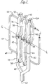
- a thin film head having a multiplicity of magnetic yokes 10, 12, 14, 16, made of Permalloy for example, that are inductively linked to an electrically conductive coil 18. Only one-half of the coil 18 is shown, with the centerline CL of the entire coil passing through vias 20a-20d.
- Each yoke comprises a first Permalloy section P1 and a second Permalloy section P2 that are connected respectively through the vias 20a-20d at back closures of the yokes and through vias 22, 24 and 26 at front closures.
- the P1 and P2 sections of each yoke form an envelope that encompasses the coil base 30.
- the P1 and P2 yoke sections are made narrow, about 10-30 micrometers ( ⁇ m) for example, and the spacing between the yokes is effectively reduced to maximize the number of yokes within the area between the sides of the coil.
- the lateral spacing between adjacent yokes is more than one-half of the vertical spacing between the P1 and P2 sections of a yoke.
- the thin film head design allows making the P1 and P2 sections of the yokes very narrow, with a minimum width that is close to the working track width of the head, defined by the width of the data tracks recorded on a magnetic medium, such as a magnetic disk.
- the ratio of yoke width to data track width can be in the range of about 1.25:1 to 6:1., but in any event the yoke width is no less than the track width.
- Very narrow yokes result in a lowered inductance and serve to improve high frequency response and increase the signal-to-noise (S/N) ratio.
- the magnetic yokes are connected serially so that a continuous magnetic flux circuit is formed.
- the P2 section of yoke 10 is connected through via 22 to the P1 section of yoke 12
- the P2 section of yoke 12 is connected through via 24 to the P1 section of yoke 14
- the P2 section of yoke 14 is connected through via 26 to the P1 section of yoke 16.
- a transducing gap 28 is provided between the end of the P1 section of the first yoke 10 and the P2 section of the last yoke 16 of the series of multiple yokes.
- the coil 18 is configured with a base 30, parallel sides 32 and 34 and a topside (not shown) opposite to the base.
- Write current (i) is supplied to the coil 18 during the write mode and read signals are obtained from the coil during the read mode of the device.
- a P1 layer is deposited by well known masking and etching techniques.
- the P1 layer is designed with spaced P1 sections, one for each of the magnetic yokes 10, 12, 14, 16.
- a seed layer is formed over an alumina undercoat that was laid down on a polished surface of a ceramic substrate.
- a first insulating layer of aluminum oxide which provides the transducing gap 28 between the P1 section of yoke 10 and the P2 section of yoke 16 is then deposited.
- a patterned electrical coil structure 18 is then formed and defined by photolithography masking techniques and chemical etching.
- Insulating material is deposited to cover and insulate the coil structure 18 from the P1 and P2 magnetic layers.
- the P2 layer is then deposited with spaced P2 sections that make contact through vias 20a-20d with respective P1 sections at the back closures of each yoke, and with adjacent P1 sections through vias 22, 24 and 26, except for the P2 section of the last yoke 16.
- the P2 sections are coextensive with and superposed in alignment with the P1 sections along axes that are orthogonally disposed to the planar coil 18.
- a protective insulating overcoat is deposited over the head structure, by r.f.
- Bonding pads, interconnects and wiring to the head circuit are provided to conduct data signals from and to the head during the read and write modes.
- the multiple yoke thin film magnetic head shown in Figs. 1A and 1B provide an output signal approximately four times that obtained with a conventional inductive head.
- the thin film head with multiple yokes as disclosed herein realizes a signal output about two times that available with the thin film head assembly of the head device described in the referenced application.
- the head configuration of Figs. 1A and 1B allows a reduction in thermal noise with a resultant improvement in the signal-to-noise ratio.
- Fig. 2 depicts an alternative embodiment of the invention wherein the base 68 of coil 64 is inductively linked to magnetic full yokes 42 and 44 (the yokes having both P1 and P2 sections that form an envelope around the coil), and the opposing topside 66 of the coil is inductively coupled to magnetic yokes 36, 38 and 40.
- the magnetic circuit is completed by the one-half yokes comprising the P1 section 78 and the P2 section 80 which define the transducing gap.
- the ends of the coil 64 are connected to read/write circuitry for passing data signals to the head during the record mode and from the head during the read mode.
- the P1 and P2 sections of the yokes 36, 38 and 40 are connected at vias 50, 52 and 54 respectively.
- the P1 and P2 sections of yokes 42 and 44 are connected through vias 58 and 60. All of the yokes are tied at vias 56 to establish a continuous magnetic flux path.
- the additional magnetic yoke envelopes 36, 38 and 40 increase the amount of flux linkage substantially.
- the foldover or envelope type structure of Fig. 2, wherein a plurality of yokes is inductively coupled to one part of the coil and a second plurality of yokes is inductively coupled to an opposite part of the coil affords a significant gain in signal output.
- the gain in signal realized with this implementation is approximately six times that of a conventional head using the same number of coil turns.
- FIG. 3 A variation of the novel design of a thin film head formed with yoke envelopes around a coil is illustrated in Fig. 3.
- the P1 yoke sections which are disposed below the plane of the coil 18 form an angle relative to the P2 yoke sections, which are formed above the coil layer and are substantially parallel to the sides 32 and 34 of the coil.
- the P1 and P2 yoke sections are connected through vias 70, 72, 74, 76 disposed along the centerline of the coil between the sides 32 and 34.
- the P1 and P2 yoke sections are also connected through vias 78, 80, 82 formed external to the perimeter of the coil 18.
- Another embodiment of the invention comprises angled yokes, as shown in Fig. 2, encompassing both the upper and lower parts of the coil.
- the overall height of the coil can be reduced from that used with conventional thin film heads, which typically require a coil height that is about 80% of the thickness of the head slider on which the thin film transducer is deposited.
- a slider of smaller thickness can be used and space requirements reduced.
- a yoke envelope is formed with an array of substantially parallel P1 Permalloy strips and an array of substantially parallel P2 Permalloy strips.
- the P1 strips are disposed at an angle relative to opposing legs of a coil 84, whereas the P2 strips are disposed substantially perpendicular to the coil legs.
- the P1 and P2 strips are connected at vias 86 and 92 which are external to the coil 84 and at vias 88 and 90 which are interior to the coil 84.
- the connected strips encompass the coil legs at uniformly spaced areas.
- a transducing gap 94 is provided at the connection of the P1 and P2 elements located at the upper center of the yoke.
- an orienting DC magnetic field H is applied at an angle orthogonal to the length of the P1 strips.
- the apparatus for applying a second orienting DC magnetic field is shifted so that the applied field is substantially perpendicular to the P2 strips.
- the yoke width is made to be within the range of 4-30 microns.
- the coil 84 can be made with multiple terms as well as a single term.
- the thin film head configurations use a multiplicity of yokes that envelop a coil in a foldover configuration, the yokes being oriented relative to the coil so that a maximum number of flux linkages are obtained for a given area occupied by the coil.
- the closely spaced narrow magnetic yokes which are linked to multiple parts of a coil structure provide the advantages of increased signal output and reduced thermal noise.
- the coil structure used with the head design may incorporate more than a single planar coil and the coil may have more than a single turn.
- the coil can be other than square or rectangular in shape.
- a thin film magnetic head is fabricated with a multiplicity of magnetic yokes that interact effectively with an electrical coil.
- the magnetic P1 and P2 pole sections of the yoke are very narrow and form closely spaced envelopes about the coil.
- the multiple yokes are inductively linked to the coil so as to provide an increased number of flux interactions for a given length of coil turn.
Landscapes
- Engineering & Computer Science (AREA)
- Manufacturing & Machinery (AREA)
- Magnetic Heads (AREA)
Applications Claiming Priority (2)
| Application Number | Priority Date | Filing Date | Title |
|---|---|---|---|
| US87822692A | 1992-05-04 | 1992-05-04 | |
| US878226 | 1992-05-04 |
Publications (2)
| Publication Number | Publication Date |
|---|---|
| EP0568966A2 true EP0568966A2 (en) | 1993-11-10 |
| EP0568966A3 EP0568966A3 (enExample) | 1994-04-13 |
Family
ID=25371622
Family Applications (1)
| Application Number | Title | Priority Date | Filing Date |
|---|---|---|---|
| EP93107181A Withdrawn EP0568966A2 (en) | 1992-05-04 | 1993-05-03 | Thin film magnetic heads with multiple yokes |
Country Status (3)
| Country | Link |
|---|---|
| EP (1) | EP0568966A2 (enExample) |
| KR (1) | KR940006079A (enExample) |
| CN (1) | CN1078567A (enExample) |
Cited By (1)
| Publication number | Priority date | Publication date | Assignee | Title |
|---|---|---|---|---|
| EP0727772A3 (en) * | 1995-02-17 | 1997-04-23 | Aiwa Co | Thin film head arrangement with coil and with cocoon structure for protection and planarization |
Family Cites Families (8)
| Publication number | Priority date | Publication date | Assignee | Title |
|---|---|---|---|---|
| JPS545710A (en) * | 1977-06-15 | 1979-01-17 | Fujitsu Ltd | Thin-film magnetic head |
| US4165525A (en) * | 1978-02-15 | 1979-08-21 | U.S. Philips Corporation | Magnetic head having a core provided on a substrate by means of thin-film technology |
| JPS5766520A (en) * | 1980-10-08 | 1982-04-22 | Nippon Telegr & Teleph Corp <Ntt> | Thin-film type magnetic head |
| JPS60129915A (ja) * | 1983-12-15 | 1985-07-11 | Seikosha Co Ltd | 薄膜磁気ヘツド |
| JPS6185612A (ja) * | 1984-10-03 | 1986-05-01 | Toko Inc | 薄膜磁気ヘツド |
| US5311386A (en) * | 1989-06-02 | 1994-05-10 | Digital Equipment Corporation | Transducer with improved inductive coupling |
| EP0400793A3 (en) * | 1989-06-02 | 1991-01-23 | Quantum Corporation | Transducer with improved inductive coupling |
| US5184267A (en) * | 1989-06-02 | 1993-02-02 | Digital Equipment Corporation | Transducer with improved inductive coupling |
-
1993
- 1993-05-03 EP EP93107181A patent/EP0568966A2/en not_active Withdrawn
- 1993-05-03 CN CN 93105030 patent/CN1078567A/zh active Pending
- 1993-05-03 KR KR1019930007595A patent/KR940006079A/ko not_active Withdrawn
Cited By (2)
| Publication number | Priority date | Publication date | Assignee | Title |
|---|---|---|---|---|
| EP0727772A3 (en) * | 1995-02-17 | 1997-04-23 | Aiwa Co | Thin film head arrangement with coil and with cocoon structure for protection and planarization |
| US5684660A (en) * | 1995-02-17 | 1997-11-04 | Aiwa Research And Development, Inc. | Thin film coil head assembly with protective planarizing cocoon structure |
Also Published As
| Publication number | Publication date |
|---|---|
| EP0568966A3 (enExample) | 1994-04-13 |
| KR940006079A (ko) | 1994-03-23 |
| CN1078567A (zh) | 1993-11-17 |
Similar Documents
| Publication | Publication Date | Title |
|---|---|---|
| US5995342A (en) | Thin film heads having solenoid coils | |
| US6125014A (en) | Via-less connection using interconnect traces between bond pads and a transducer coil of a magnetic head slider | |
| US6195232B1 (en) | Low-noise toroidal thin film head with solenoidal coil | |
| EP0669607A2 (en) | Magnetic head assembly with MR sensor | |
| JP2003030803A (ja) | 磁気ヘッド組立体およびその製造方法 | |
| US5130877A (en) | Thin film head on ferrite substrate with inclined top pole | |
| JPH0475570B2 (enExample) | ||
| JPH05159234A (ja) | 変化する厚さのコイルを備えた薄膜ヘッド | |
| EP0675486A2 (en) | Integrated yoke magnetoresistive transducer with magnetic shunt | |
| US5184394A (en) | Method of making a thin film head on ferrite substrate with inclined top pole | |
| US5312644A (en) | Method of making a magnetoresistive head with integrated bias and magnetic shield layer | |
| US5452168A (en) | Thin film magnetic heads with multiple yokes | |
| KR100381318B1 (ko) | 자기기록/재생헤드 | |
| EP0541943A2 (en) | Thin film magnetic head with narrow yoke | |
| EP0612060B1 (en) | Transducer with improved inductive coupling | |
| US20040100728A1 (en) | Thin film magnetic head including coil wound in toroidal shape and method for manufacturing the same | |
| US3718776A (en) | Multi-track overlapped-gap magnetic head, assembly | |
| JPH0233290Y2 (enExample) | ||
| EP0568966A2 (en) | Thin film magnetic heads with multiple yokes | |
| US6563674B1 (en) | Thin-film magnetic head | |
| JPH0644524A (ja) | 磁気変換器及び磁気変換器を製造する方法 | |
| US5428893A (en) | Method of making a transducer with improved inductive coupling | |
| Lier et al. | Combined thin film magnetoresistive read, inductive write heads | |
| JPS62256209A (ja) | 薄膜磁気ヘツド | |
| JPH0673167B2 (ja) | 薄膜磁気ヘツド |
Legal Events
| Date | Code | Title | Description |
|---|---|---|---|
| PUAI | Public reference made under article 153(3) epc to a published international application that has entered the european phase |
Free format text: ORIGINAL CODE: 0009012 |
|
| AK | Designated contracting states |
Kind code of ref document: A2 Designated state(s): DE FR GB NL |
|
| PUAL | Search report despatched |
Free format text: ORIGINAL CODE: 0009013 |
|
| AK | Designated contracting states |
Kind code of ref document: A3 Designated state(s): DE FR GB NL |
|
| 17P | Request for examination filed |
Effective date: 19940920 |
|
| 17Q | First examination report despatched |
Effective date: 19961030 |
|
| 18D | Application deemed to be withdrawn |
Effective date: 19970311 |