EP0568793A2 - Agencement de sièges arriére pour omnibus - Google Patents
Agencement de sièges arriére pour omnibus Download PDFInfo
- Publication number
- EP0568793A2 EP0568793A2 EP93103806A EP93103806A EP0568793A2 EP 0568793 A2 EP0568793 A2 EP 0568793A2 EP 93103806 A EP93103806 A EP 93103806A EP 93103806 A EP93103806 A EP 93103806A EP 0568793 A2 EP0568793 A2 EP 0568793A2
- Authority
- EP
- European Patent Office
- Prior art keywords
- seat cushion
- lever
- seat
- backrest
- cushion frame
- Prior art date
- Legal status (The legal status is an assumption and is not a legal conclusion. Google has not performed a legal analysis and makes no representation as to the accuracy of the status listed.)
- Granted
Links
Images


Classifications
-
- B—PERFORMING OPERATIONS; TRANSPORTING
- B60—VEHICLES IN GENERAL
- B60N—SEATS SPECIALLY ADAPTED FOR VEHICLES; VEHICLE PASSENGER ACCOMMODATION NOT OTHERWISE PROVIDED FOR
- B60N2/00—Seats specially adapted for vehicles; Arrangement or mounting of seats in vehicles
- B60N2/24—Seats specially adapted for vehicles; Arrangement or mounting of seats in vehicles for particular purposes or particular vehicles
- B60N2/242—Bus seats
-
- B—PERFORMING OPERATIONS; TRANSPORTING
- B60—VEHICLES IN GENERAL
- B60N—SEATS SPECIALLY ADAPTED FOR VEHICLES; VEHICLE PASSENGER ACCOMMODATION NOT OTHERWISE PROVIDED FOR
- B60N2/00—Seats specially adapted for vehicles; Arrangement or mounting of seats in vehicles
- B60N2/005—Arrangement or mounting of seats in vehicles, e.g. dismountable auxiliary seats
- B60N2/015—Attaching seats directly to vehicle chassis
- B60N2/01508—Attaching seats directly to vehicle chassis using quick release attachments
- B60N2/01516—Attaching seats directly to vehicle chassis using quick release attachments with locking mechanisms
Definitions
- the invention relates to a rear seat arrangement for buses and coaches according to the preamble of patent claim 1.
- the Road Traffic Licensing Regulations require that the rear window be designed as an emergency exit so that a cylindrical test specimen with a diameter of 550 mm and a length of 1400 mm can be transported out of the bus through the opening.
- the backrests of the rear seats protrude beyond the lower edge of the rear window and thus reduce the opening prescribed as an emergency exit.
- seat constructions have been developed that allow the backrest protrusions to be removed from the window opening.
- the seat frame of each rear seat is guided in longitudinal rails on the vehicle floor and the backrest in a link attached to the rear wall of the vehicle. If the seat cushion is pulled forward, the lower part of the backrest is thereby shifted forward and the backrest slides out of its steep position into a more horizontal extension in the backdrop, with its upper edge below the lower edge of the window opening of the rear window submerges. This completely clears the window opening and is available as an approved emergency exit.
- a similar seat construction is known from rail vehicles (DE 20 54 817 A1), in which, for the purpose of converting the seat into a lying surface, a control pin is arranged at the lower end of the backrest frame, which runs in a rail guide that runs obliquely downwards beneath the seat frame rail guide .
- the invention has for its object to provide a rear seat assembly of the type mentioned, which is independent of the installation conditions in the vehicles and in which the at least two, preferably all rear seats of the rear seat assembly are simultaneously transferred with a single handle in the forward releasing position releasing the emergency exit can.
- the rear seat assembly according to the invention has the advantage that all the seat cushions of the rear seats are pulled forward together by means of the provided handle with a single actuation movement, namely lifting and pulling in the direction of travel of the bus, so as to create the necessary space for folding the backrests away, and at the same time all backrests are inclined backwards at least to the extent that they are swung out of the opening in the rear window.
- All elements for the forced movement of the backrest are fastened to the seat cushion frame or to the rail-mounted rail guide of the seat cushion frame.
- the two guide rails provided for each rear seat are connected to one another so that they can be installed in the vehicle in just a few simple steps. The time for the final assembly of the rear seat arrangement is thus considerably reduced.
- the lever linkage for the forced actuation of the backrest can be produced very easily in terms of production technology if, according to an expedient embodiment of the invention, two two-armed levers are provided, which are each pivotably held at the front and rear ends of the seat cushion frame, as seen in the direction of travel.
- One lever arm of the rear lever is firmly connected to the backrest and one lever arm of the front lever is articulated to the guide rod.
- the other two lever arms are connected to each other via a hinged coupling rod.
- the triggering of the swivel mechanism for the backrest can be derived in a simple manner from the displacement movement of the seat cushion frame in that, according to a preferred embodiment of the invention, the guide rod carries a transversely projecting guide bolt which is guided in a seat cushion frame-fixed backdrop extending in the displacement direction of the seat cushion frame and in the seat use position at the front end of the link, as seen in the direction of travel, is locked in the backdrop against displacement.
- a stop which is fixed to the vehicle is arranged such that after a predetermined displacement path of the seat cushion frame in the direction of travel, the locking of the guide pin of the link is lifted and the guide bolt is fixed at the stop against displacement.
- the guide pin is preferably locked by a leaf spring which presses the guide pin into a groove formed at the front end of the link.
- the stop has a run-up slope, through which the guide pin is raised against the force of the leaf spring to such an extent that it runs into the elongated part of the link extending in the direction of displacement of the seat cushion frame.
- the guide rod can also be displaceably guided with a transversely projecting guide pin in a longitudinal slot fixed to the vehicle and extending parallel to the rail guide.
- the longitudinal slot is dimensioned such that after a predetermined displacement of the seat cushion frame in the direction of travel, the vehicle pin strikes the front end of the longitudinal slot as viewed in the direction of travel.
- Such a solution is preferably used in particular when the seat cushion and backrest are not rigidly connected to one another in the seat use position, but the rear seats are designed such that the angle of inclination of the backrest relative to the seat cushion can be set within a predetermined angular range.
- the design and assignment of the guide rod and guide slot is made so that in a seat use position, in which the rear end of the seat cushion, as seen in the direction of travel, is as close as possible to the rear wall of the vehicle and the backrest is at the steepest angle, the guide pin is not yet or just now on the rear End of the longitudinal slot.
- an adjusting element which is adjustable in the direction of the seat cushion displacement acts on the front two-armed lever of the lever linkage between its pivot bearing point and the articulation point of the guide rod.
- the push-out piston of a gas spring is preferably used as such an adjusting member, the gas spring being installed in such a way that when the gas spring is triggered and the longitudinal displacement of a fastening section of the gas spring caused thereby, the backrest is raised. When the gas spring is unlocked, the backrest is lowered by the pressure exerted by the seat user on the leaning surface of the backrest.
- each locking device for the stationary locking of the seat cushion frame has a locking bar which extends parallel to the rail guide and is fixed to the seat cushion frame and which can be locked in a vehicle-fixed manner at least in the seat use position.
- the handle is designed as a handlebar extending transversely to the direction of displacement of the rear seats over their entire width, which is rigidly or couplably connected to the locking bars.
- the handlebar For rear seats with a fixed backrest connection in the seating position, the handlebar is firmly connected to all locking strips of the rear seats. By lifting the handlebar all locking devices are released and pulling the handlebar pulls all seat cushion frames of the rear seats forward over their locking strips.
- the handle bar In rear seats with backrests adjustable in inclination to the seat cushion, the handle bar is rigidly attached to at least two longitudinal members that can be swiveled and moved longitudinally and within certain limits.
- a locking bar extending across the entire width of the rear seats is fastened to the two longitudinal beams which extend parallel to one another in the direction of seat displacement.
- a connecting lever is attached to each locking bar and is articulated on the actuating lever for the backrest inclination adjustment.
- the locking bar By pulling the handle bar, the locking bar is pulled forward and, after it has fallen into all the locking hooks provided at the front end of the locking bars, pulls all seat cushion frames over the locking bars with it, the backrests being forcibly pivoted when the gas springs are unlocked .
- the rear seat arrangement for a coach schematically outlined in side view in FIG. 1 and in plan view in FIG. 2 has a plurality of rear seats 10 (FIG. 1) or 10, 10 ′ and 10 ′′ (FIG. 2) arranged next to one another transversely to the direction of travel. on.
- Each rear seat 10 consists in a known manner of a seat cushion 11 and a backrest 12.
- Das Seat cushion 11 has a seat cushion frame 13 and a seat cushion cushion 14 held thereon, and the backrest 12 has a backrest frame 15 and a backrest cushion 16 received by the latter.
- the seat cushion frame 13 is held in a vehicle-fixed rail guide 17, consisting of two longitudinal rails 17 'and 17''(Fig. 2), in the vehicle longitudinal direction.
- the longitudinal rail 17 ' shows a longitudinal rail 17 'in its constructive design.
- the longitudinal rail 17 ' consists of a lower rail 18 fixed to the vehicle and an upper rail 19 fixed to the seat cushion frame, which is guided in the lower rail 18 via a ball bearing 20.
- the two lower rails 18 are fastened at a distance from one another on a seat subframe 21 by means of screws 22, which in turn is anchored to the vehicle floor 24 by screws 23.
- the anchoring takes place in such a way that, as is sketched in Fig.
- each rear seat 10 is locked against axial displacement by a locking device 27.
- the locking device 27 which is only indicated schematically in FIGS. 1 and 2 and can be seen in cross section in FIG. 6, has a locking bar 28 fastened to the seat cushion frame 13, which extends near the longitudinal rail 17 'of the rail guide 17 parallel to the latter.
- the locking bar 28 engages over a toothed bar 29 which laterally rises up on the seat subframe 21 and interacts with it in such a way that the seat cushion frame 13 in various displacement positions along the rail guide 17, but at least in that in FIG. 1 outlined seat use position can be locked in place.
- a handle 30 is provided, which is designed as a handle bar 31, which extends over the entire width of the rear seat arrangement, seen transversely to the direction of travel, and is fastened to each locking bar 28 on the rear seats 10, 10 ', 10''at their front end, as seen in the direction of travel. If the handlebar 31 is raised, locking bars 28 and toothed bars 29 of the locking devices 27 on the rear seats 10, 10 ', 10''disengage, and pulling the handlebar 31 allows all the seat cushion frames 13 to move forward via the locking bars 28 the vehicle rear wall 25 are moved.
- the backrest 12 is connected to the seat cushion 11 via a lever linkage 32 such that, when the cushion is moved forward, the backrest 12 is forced into the described, more horizontal extension in the direction below the rear window 26 is folded down.
- the lever linkage 32 has two two-armed levers 33, 34 pivotably mounted on the seat cushion frame 13, of which one lever 33 is arranged at the front end in the direction of travel and the other lever 34 is arranged at the rear end of the seat cushion 11.
- the upper lever arm of the rear lever 34 is fixedly connected to the backrest frame 15, while the lower lever arm of the front two-arm lever 33 is articulated to a guide rod 35 which extends towards the rear end of the seat cushion 11.
- the two other lever arms of the front and rear lever 33, 34 are connected to one another by a coupling rod 36, which is articulated at the end of each of the lever arms.
- a coupling rod 36 which is articulated at the end of each of the lever arms.
- the guide rod 36 is guided with a transversely projecting guide pin 37 in a link 38 which is formed in a side plate 40 which is fastened to the seat cushion frame 13 by means of screws 39 and is angled downwards.
- the backdrop 38 extends in the longitudinal direction of the seat cushion frame adjustment and has at the rear end seen in the direction of travel a larger-diameter opening 41 and at the front end seen in the direction of travel a downward curved curvature 42 which ends in a semicircular groove 43 toward the vehicle floor 24.
- the guide pin 37 has a pin shaft 37 'and one at the free end of the pin shaft 37' radially over the latter protruding bolt head 37 ''.
- the width of the link 38 is dimensioned slightly larger than the outer diameter of the bolt shaft 37 and the opening 41 slightly larger than the outer diameter of the bolt head 37 '', so that the guide pin 37 can be threaded through the opening 41 into the link 38.
- the arrangement of the link 38 and its dimension extending in the direction of displacement of the seat cushion frame 13 are determined such that in the seat use position shown in FIG. 1, the guide pin 37 lies in the groove 43 at the front end of the link 38 and when the backrest is in the folded-down position 12 comes to lie immediately in front of the opening 41.
- the guide pin 37 lying in the groove 43 is locked there by means of a leaf spring 44 against displacement in the link 38.
- a stop 45 fixed to the vehicle is arranged such that, after a predetermined displacement path of the seat cushion frame 13 in the direction of travel, the guide pin 37 held by the leaf spring 44 in the groove 43 strikes against this stop 45.
- the guide pin 37 is then lifted out of the groove 43 by the stop 45 and slides into the link 38 so that the link 38 and guide pin 37 can move relative to one another.
- the stop 45 is formed here by an angled plate 46 which is fastened to the seat subframe 21 by means of screws 47 and extends with its leg angled from the seat subframe 21 parallel to the side plate 40 with a link 38 (FIG. 6).
- a sack-shaped incision 48 is provided in the erected leg and extends at an angle of rise of approximately 45 °.
- the opening of the incision 48 is at the same distance from the seat subframe 21, which also takes the groove 43 in the backdrop 38 of the seat frame 21.
- the guide pin 37 fixed in the groove 43 by the leaf spring 44 slides into the incision 48 and is pressed upward by the lower edge of the incision 48 forming a run-up slope 49, whereby it exits the groove 43 against the force of the leaf spring 44 the curvature 42 is transferred into the backdrop 38.
- FIGS. 1, 3 and 4. The pivoting movement of the backrest 12 when moving the rear seat 10 is illustrated in FIGS. 1, 3 and 4.
- the rear seat 10 assumes the position outlined in FIG. 1.
- the guide pin 37 at the end of the guide rod 35 is locked in the groove 43 lying at the front end of the link 38 by the leaf spring 44 on the seat cushion frame 13.
- the stop 45 is at a distance from the backdrop 38 and the guide pin 37 (Fig. 1). If the seat cushion frame 13 of the rear seat 10 is now pulled forward via the locking bar 28 in the direction of travel after the locking device 27 has been unlocked, the position of the backrest 12 initially remains unchanged until the guide bolt locked in the groove 43 37 strikes the stop 45. This is outlined in Fig. 3.
- the seat displacement initially creates a free space between the rear seat end and the vehicle rear wall 25, which is required for the folding-back movement of the backrest 12. If the seat cushion frame 13 is now moved further in the direction of travel, the guide pin 37 is lifted out of the groove 43 via the run-up slope 49 and slides over the curvature 42 into the setting 38 move the stop 45 guide bolt 37 fixed to the vehicle. When the seat cushion frame 13 is moved, the pivot bearing point 50 of the front lever 33 becomes after moved forward and pivoted about its pivot bearing point 50 counterclockwise due to the fixed guide pin 37 on the guide rod 35 of the lever 33.
- This pivoting movement of the front pivot lever 33 is transmitted via the coupling rod 36 to the rear pivot lever 34, which is turned clockwise and thereby swivels the backrest 12 downward by an angle ⁇ .
- the pivoting angle ⁇ of the backrest 12 is dimensioned such that the upper edge of the backrest 12 comes to rest at the end of the displacement path of the seat cushion frame 13 below the lower edge of the rear window 26.
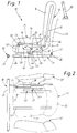
- FIGS. 7-9 Such a rear seat 110 is shown in detail in a constructive embodiment in FIGS. 7-9, these figures only illustrating the area of the seat cushion 111. Insofar as construction elements of this rear seat 110 match those in the rear seat 10 described above, they are provided with the same reference numerals, which, however, are increased by 100 to distinguish them. As can be seen from FIGS.
- the seat cushion frame 113 of the seat cushion 111 is in turn guided in a rail guide 117, which is of identical design, as described for FIG. 6.
- the lever linkage 132 pivotally held on the seat cushion frame 113 is designed in the same way as in FIGS. 5 and 6, so that reference is made to the description there.
- FIGS. 8 and 9 there is a cross on the end of the guide rod 135 protruding guide pin 151 bent in one piece, which protrudes into a longitudinal slot 152, which likewise forms a backdrop, in a mounting part 153 fixed to the vehicle and is guided therein.
- the mounting part 153 is in turn fastened to the seat subframe 121.
- the arrangement of the mounting part 153 and the length of the longitudinal slot 152 are in turn dimensioned such that, after a predetermined displacement path of the seat cushion frame 113, the guide pin 151 strikes the front end of the longitudinal slot 152, as seen in the direction of travel, and is thus immutably fixed during the further movement of the seat cushion frame 113.
- the guide pin 151 is in the seat use position and an average angle of attack within a possible angle of attack range of the backrest 12 to the seat cushion 11 about the same distance from both ends of the longitudinal slot 152, so that when the angle of attack to the backrest 12 of the guide pin 151 is in the longitudinal slot 152 can move and thus the adjustment movement of the backrest 12 is not hindered. At the same time, this also enables the seat cushion 111 to be adjusted to different displacement positions.
- a gas spring 154 is provided which extends in the direction of displacement of the seat cushion frame 113 and is fastened to it. Its fastening section 155, which is formed on the housing of the gas spring 154 in the direction of travel, articulates at the end on the lower lever arm of the front two-armed lever 133 of the lever linkage 132, namely between the pivot bearing point 150 of this lever 133 on the seat cushion frame 113 and the articulation point of the guide rod 135.
- the gas spring 154 becomes unlocked by a trigger lever 156 which over a transmission rod 157 is coupled to a hinge plate 158 pivotally held on the seat cushion frame 113.
- the transmission rod 157 is articulated on the one hand on the one-armed trigger lever 156 and on the other hand on the hinge plate 158.
- An actuating lever 159 for the backrest inclination adjustment is rigidly connected to the bearing shaft of the articulated plate 158. If the actuating lever 159 in FIG. 7 is pivoted clockwise, the trigger lever 156 in FIG. 7 is also rotated clockwise via the transmission rod 157 and thereby actuates a trigger pin 160 of the gas spring 154. As a result, the fastening section 155 moves to the left and the front lever 133 is swiveled clockwise.
- the rear lever 134 mounted on the seat cushion frame 113 is pivoted counterclockwise and the backrest is erected, that is to say set more steeply relative to the seat cushion 111. If the angle of the backrest is to be reduced, i.e. the opening angle between the seat cushion and the backrest cushion is to be increased, the seat user must push the backrest backwards with the actuation lever 159 pulled and the gas spring 154 unlocked thereby until he has reached the desired inclination position of the backrest. After releasing the actuating lever 159, the gas spring 154 is blocked and the backrest inclination achieved is thus permanently set.
- the seat cushion frame 113 which is longitudinally displaceable in the rail guide 117, can in turn be locked in various desired seating positions by a locking device 127.
- the locking device 127 is designed in a similar manner to that described for FIGS. 1-6.
- a single handle 130 is provided, with which all locking devices 127 of all rear seats 110 are released simultaneously and all seat cushion frames 113 of all rear seats 110 are pulled forward in the direction of travel can, so that in an emergency the rear seat assembly can be moved forward very quickly and the rear window opening can be cleared.
- the handle 130 is in turn formed here by a handle bar 131 which extends across the width of the entire rear seat arrangement seen transversely to the direction of travel. As can be seen from FIGS.
- the handle bar 131 is rigidly fastened to at least two longitudinal beams which are fixed to the vehicle and are longitudinally displaceable within limits.
- the side members only one side member 161 can be seen in FIGS. 7 and 9. It is pivotally held at its rear end in the direction of travel on the seat subframe 121 and is designed telescopically in the front area, a push rod 162 with a U-shaped cross section being guided within the cross-sectionally U-shaped longitudinal member 161 so as to be longitudinally displaceable within limits.
- the handle bar 131 is attached to the front end of the extension bar 162 facing away from the longitudinal member 161.
- the maximum extension path of the extension rod 162 corresponds to the maximum displacement path of the seat cushion frame 113 in the rail guide 117.
- the locking device 127 assigned to each rear seat 110 in turn has a locking bar 128 firmly connected to the seat cushion frame 113, on the front end of which, viewed in the direction of travel, a locking hook 163 is formed (FIG. 7).
- a locking bar 164 is fastened to the two longitudinal beams 161 and extends parallel to the handle bar 131 over the entire width of the rear seat arrangement.
- This locking bar 164 which, like the handle bar 131, is also attached to the underside of the push-out bars 162, is designed such that it can drop into the locking hooks 163 of the locking bar 128, for which purpose these locking hooks 163 are open at the bottom. If the locking bar 164 lies in the locking hook 163, then all are Locking bars 128 are rigidly connected to one another, and all seat cushion frames 113 of the rear seats 110 can be pulled forward by pulling the handle bar 131.
- a connecting lever 165 is attached to each locking bar 128, which is articulated on the joint plate 158 via a slot-pin connection 166.
- the handle bar 131 is to be slightly raised, the longitudinal members 161 pivoting slightly clockwise in FIG. 7.
- the locking bar 164 resting on the underside of the locking bars 128 lifts them and disengages them from the toothed bars 129.
- the locking devices 127 are released.
- the respective joint plate 158 is rotated clockwise in FIG.
- the actuating lever 159 for adjusting the backrest inclination is also coupled to the locking device 127 of the rear seat 110 by the connecting lever 165, so that the locking device 127 is also released by its actuation.
- the seat user can also change the seating position of the seat cushion 11 along the rail guide 117.
Applications Claiming Priority (2)
| Application Number | Priority Date | Filing Date | Title |
|---|---|---|---|
| DE4211921 | 1992-04-09 | ||
| DE19924211921 DE4211921C2 (de) | 1992-04-09 | 1992-04-09 | Fondsitzanordnung für Omnibusse |
Publications (3)
| Publication Number | Publication Date |
|---|---|
| EP0568793A2 true EP0568793A2 (fr) | 1993-11-10 |
| EP0568793A3 EP0568793A3 (en) | 1994-05-18 |
| EP0568793B1 EP0568793B1 (fr) | 1996-06-05 |
Family
ID=6456455
Family Applications (1)
| Application Number | Title | Priority Date | Filing Date |
|---|---|---|---|
| EP19930103806 Expired - Lifetime EP0568793B1 (fr) | 1992-04-09 | 1993-03-10 | Agencement de sièges arriére pour omnibus |
Country Status (3)
| Country | Link |
|---|---|
| EP (1) | EP0568793B1 (fr) |
| DE (1) | DE4211921C2 (fr) |
| ES (1) | ES2090738T3 (fr) |
Cited By (5)
| Publication number | Priority date | Publication date | Assignee | Title |
|---|---|---|---|---|
| EP0738624A1 (fr) * | 1995-04-19 | 1996-10-23 | KEIPER RECARO GmbH & Co. | Siège de véhicule automobile, en particulier siège arrière ou banquette arrière |
| FR2745244A1 (fr) * | 1996-02-22 | 1997-08-29 | Peugeot | Vehicule automobile equipe d'une banquette arriere deplacable et transformable |
| EP0875415A3 (fr) * | 1997-04-28 | 1999-03-03 | NMI Safety Systems Ltd. | Support de siège |
| CN106143219A (zh) * | 2015-03-30 | 2016-11-23 | 长城汽车股份有限公司 | 汽车、座垫总成及座垫翻折机构 |
| CN108974033A (zh) * | 2017-06-05 | 2018-12-11 | 中车唐山机车车辆有限公司 | 一种座椅及列车车厢 |
Families Citing this family (1)
| Publication number | Priority date | Publication date | Assignee | Title |
|---|---|---|---|---|
| CN115188254B (zh) * | 2022-07-12 | 2024-01-19 | 一汽奔腾轿车有限公司 | 一种座椅靠背角度调节人体卡板结构及调节方法 |
Citations (8)
| Publication number | Priority date | Publication date | Assignee | Title |
|---|---|---|---|---|
| FR2424167A2 (fr) * | 1978-04-26 | 1979-11-23 | Compin Ets | Siege reglable, en particulier pour voitures de chemin de fer |
| DE2911027A1 (de) * | 1978-11-13 | 1980-05-22 | Max Michel Francois Chardon | Sitz, insbesondere fuer oeffentliche transportfahrzeuge |
| DE3534689A1 (de) * | 1985-09-28 | 1987-04-16 | Hans Dipl Ing Kuehl | Sitz fuer ein transportsystem |
| EP0229625A2 (fr) * | 1986-01-09 | 1987-07-22 | Paulisch KG | Siège pour véhicules de transport en commun |
| EP0260631A1 (fr) * | 1986-09-16 | 1988-03-23 | FIAT AUTO S.p.A. | Dispositif de réglage de l'inclinaison du siège arrière d'un véhicule |
| EP0476253A1 (fr) * | 1990-09-12 | 1992-03-25 | Inventio Ag | Siège réglable de véhicule |
| JPH04135924A (ja) * | 1990-09-27 | 1992-05-11 | Mazda Motor Corp | 車両のシート装置 |
| JPH04201633A (ja) * | 1990-11-30 | 1992-07-22 | Mazda Motor Corp | 自動車の室内後部構造 |
Family Cites Families (1)
| Publication number | Priority date | Publication date | Assignee | Title |
|---|---|---|---|---|
| DE2054817C3 (de) * | 1970-11-07 | 1979-01-18 | Bremshey Ag, 5650 Solingen | Sitzeinrichtung, insbesondere für Schienenfahrzeuge |
-
1992
- 1992-04-09 DE DE19924211921 patent/DE4211921C2/de not_active Expired - Fee Related
-
1993
- 1993-03-10 EP EP19930103806 patent/EP0568793B1/fr not_active Expired - Lifetime
- 1993-03-10 ES ES93103806T patent/ES2090738T3/es not_active Expired - Lifetime
Patent Citations (8)
| Publication number | Priority date | Publication date | Assignee | Title |
|---|---|---|---|---|
| FR2424167A2 (fr) * | 1978-04-26 | 1979-11-23 | Compin Ets | Siege reglable, en particulier pour voitures de chemin de fer |
| DE2911027A1 (de) * | 1978-11-13 | 1980-05-22 | Max Michel Francois Chardon | Sitz, insbesondere fuer oeffentliche transportfahrzeuge |
| DE3534689A1 (de) * | 1985-09-28 | 1987-04-16 | Hans Dipl Ing Kuehl | Sitz fuer ein transportsystem |
| EP0229625A2 (fr) * | 1986-01-09 | 1987-07-22 | Paulisch KG | Siège pour véhicules de transport en commun |
| EP0260631A1 (fr) * | 1986-09-16 | 1988-03-23 | FIAT AUTO S.p.A. | Dispositif de réglage de l'inclinaison du siège arrière d'un véhicule |
| EP0476253A1 (fr) * | 1990-09-12 | 1992-03-25 | Inventio Ag | Siège réglable de véhicule |
| JPH04135924A (ja) * | 1990-09-27 | 1992-05-11 | Mazda Motor Corp | 車両のシート装置 |
| JPH04201633A (ja) * | 1990-11-30 | 1992-07-22 | Mazda Motor Corp | 自動車の室内後部構造 |
Non-Patent Citations (2)
| Title |
|---|
| PATENT ABSTRACTS OF JAPAN vol. 16, no. 405 (M-1301)26. August 1992 & JP-A-04 135 924 (SAKANE KATSUMI) * |
| PATENT ABSTRACTS OF JAPAN vol. 16, no. 538 (M-1335)9. November 1992 & JP-A-04 201 633 (AOKI HIKEDI) * |
Cited By (6)
| Publication number | Priority date | Publication date | Assignee | Title |
|---|---|---|---|---|
| EP0738624A1 (fr) * | 1995-04-19 | 1996-10-23 | KEIPER RECARO GmbH & Co. | Siège de véhicule automobile, en particulier siège arrière ou banquette arrière |
| FR2745244A1 (fr) * | 1996-02-22 | 1997-08-29 | Peugeot | Vehicule automobile equipe d'une banquette arriere deplacable et transformable |
| EP0875415A3 (fr) * | 1997-04-28 | 1999-03-03 | NMI Safety Systems Ltd. | Support de siège |
| CN106143219A (zh) * | 2015-03-30 | 2016-11-23 | 长城汽车股份有限公司 | 汽车、座垫总成及座垫翻折机构 |
| CN106143219B (zh) * | 2015-03-30 | 2018-10-16 | 长城汽车股份有限公司 | 汽车、座垫总成及座垫翻折机构 |
| CN108974033A (zh) * | 2017-06-05 | 2018-12-11 | 中车唐山机车车辆有限公司 | 一种座椅及列车车厢 |
Also Published As
| Publication number | Publication date |
|---|---|
| EP0568793A3 (en) | 1994-05-18 |
| DE4211921A1 (de) | 1993-10-14 |
| EP0568793B1 (fr) | 1996-06-05 |
| DE4211921C2 (de) | 1995-09-21 |
| ES2090738T3 (es) | 1996-10-16 |
Similar Documents
| Publication | Publication Date | Title |
|---|---|---|
| EP1034974B1 (fr) | Siège de véhicule | |
| EP0985575B1 (fr) | Siège arrière de véhicule automobile à dossier rabattable et assise abaissable | |
| DE19932214B4 (de) | Fahrzeugsitz | |
| DE10050735A1 (de) | Flach umklappbarer Fahrzeugsitz | |
| DE4336278A1 (de) | Betätigungseinrichtung für ein Verdeck und einen Verdeckkastendeckel eines Kraftfahrzeuges | |
| WO2014075819A1 (fr) | Siège de véhicule, en particulier siège de véhicule automobile | |
| EP0738624A1 (fr) | Siège de véhicule automobile, en particulier siège arrière ou banquette arrière | |
| DE3801294A1 (de) | Klappbarer fahrzeugsitz | |
| DE19620872A1 (de) | Fahrzeugsitz mit in Höhe und Länge verstellbarer Sitzfläche | |
| DE2724048A1 (de) | Kraftfahrzeugsitz, insbesondere fuer zweituerige kraftfahrzeuge | |
| DE19533932A1 (de) | Sitz, insbesondere Fondsitz für Kraftfahrzeuge | |
| DE19822134C1 (de) | Befestigungsvorrichtung für einen Kindersitz auf einem Fahrzeugsitz | |
| WO2015028244A1 (fr) | Armature équipée d'un mécanisme de pivotement en avant et d'un cliquet d'accès facile ainsi que siège de véhicule équipé d'une telle armature | |
| DE10047743A1 (de) | Klappbarer Sitz, insbesondere für ein Kraftfahrzeug | |
| DE102005015167B4 (de) | Fahrzeugsitz | |
| DE102004030320B4 (de) | Kraftfahrzeugsitz | |
| DE19532530C1 (de) | Rücksitzanlage für ein Kraftfahrzeug, insbesondere Personenkraftwagen | |
| DE10249265B3 (de) | Kraftfahrzeugsitz mit einer crashaktiven Kopfstütze | |
| EP0568793B1 (fr) | Agencement de sièges arriére pour omnibus | |
| EP1627768B1 (fr) | Siège pliable en particulier pour véhicules automobiles | |
| DE3129063C2 (de) | Kopfstütze für Fahrzeugsitze | |
| DE4134053A1 (de) | Fahrzeugsitz | |
| DE19910084A1 (de) | Betätigungsanordnung für einen Fahrzeugsitz | |
| DE3531992A1 (de) | Verstelleinrichtung fuer eine in ihrer neigung verstellbare kraftfahrzeug-hintersitzlehne | |
| DE10011545C1 (de) | Kraftfahrzeugsitz mit beidseitig an Adaptern klappbar und neigungsverstellbar gelagerter Rückenlehne |
Legal Events
| Date | Code | Title | Description |
|---|---|---|---|
| PUAI | Public reference made under article 153(3) epc to a published international application that has entered the european phase |
Free format text: ORIGINAL CODE: 0009012 |
|
| AK | Designated contracting states |
Kind code of ref document: A2 Designated state(s): BE ES FR NL |
|
| PUAL | Search report despatched |
Free format text: ORIGINAL CODE: 0009013 |
|
| AK | Designated contracting states |
Kind code of ref document: A3 Designated state(s): BE ES FR NL |
|
| 17P | Request for examination filed |
Effective date: 19940415 |
|
| 17Q | First examination report despatched |
Effective date: 19950523 |
|
| GRAA | (expected) grant |
Free format text: ORIGINAL CODE: 0009210 |
|
| AK | Designated contracting states |
Kind code of ref document: B1 Designated state(s): BE ES FR NL |
|
| ET | Fr: translation filed | ||
| REG | Reference to a national code |
Ref country code: ES Ref legal event code: FG2A Ref document number: 2090738 Country of ref document: ES Kind code of ref document: T3 |
|
| REG | Reference to a national code |
Ref country code: ES Ref legal event code: FG2A Ref document number: 2090738 Country of ref document: ES Kind code of ref document: T3 |
|
| PLBE | No opposition filed within time limit |
Free format text: ORIGINAL CODE: 0009261 |
|
| STAA | Information on the status of an ep patent application or granted ep patent |
Free format text: STATUS: NO OPPOSITION FILED WITHIN TIME LIMIT |
|
| 26N | No opposition filed | ||
| NLS | Nl: assignments of ep-patents |
Owner name: DAIMLER-BENZ AKTIENGESELLSCHAFT |
|
| REG | Reference to a national code |
Ref country code: FR Ref legal event code: TP |
|
| NLS | Nl: assignments of ep-patents |
Owner name: DAIMLERCHRYSLER AG |
|
| PGFP | Annual fee paid to national office [announced via postgrant information from national office to epo] |
Ref country code: NL Payment date: 20000322 Year of fee payment: 8 Ref country code: FR Payment date: 20000322 Year of fee payment: 8 Ref country code: BE Payment date: 20000322 Year of fee payment: 8 |
|
| PGFP | Annual fee paid to national office [announced via postgrant information from national office to epo] |
Ref country code: ES Payment date: 20000324 Year of fee payment: 8 |
|
| PG25 | Lapsed in a contracting state [announced via postgrant information from national office to epo] |
Ref country code: ES Free format text: LAPSE BECAUSE OF NON-PAYMENT OF DUE FEES Effective date: 20010312 |
|
| PG25 | Lapsed in a contracting state [announced via postgrant information from national office to epo] |
Ref country code: BE Free format text: LAPSE BECAUSE OF NON-PAYMENT OF DUE FEES Effective date: 20010331 |
|
| BERE | Be: lapsed |
Owner name: DAIMLERCHRYSLER A.G. Effective date: 20010331 |
|
| PG25 | Lapsed in a contracting state [announced via postgrant information from national office to epo] |
Ref country code: NL Free format text: LAPSE BECAUSE OF NON-PAYMENT OF DUE FEES Effective date: 20011001 |
|
| PG25 | Lapsed in a contracting state [announced via postgrant information from national office to epo] |
Ref country code: FR Free format text: LAPSE BECAUSE OF NON-PAYMENT OF DUE FEES Effective date: 20011130 |
|
| NLV4 | Nl: lapsed or anulled due to non-payment of the annual fee |
Effective date: 20011001 |
|
| REG | Reference to a national code |
Ref country code: FR Ref legal event code: ST |
|
| REG | Reference to a national code |
Ref country code: ES Ref legal event code: FD2A Effective date: 20030203 |