EP0568456A1 - Guard rail made of wood and metal - Google Patents
Guard rail made of wood and metal Download PDFInfo
- Publication number
- EP0568456A1 EP0568456A1 EP93401109A EP93401109A EP0568456A1 EP 0568456 A1 EP0568456 A1 EP 0568456A1 EP 93401109 A EP93401109 A EP 93401109A EP 93401109 A EP93401109 A EP 93401109A EP 0568456 A1 EP0568456 A1 EP 0568456A1
- Authority
- EP
- European Patent Office
- Prior art keywords
- wood
- metal
- wooden
- safety barrier
- barrier according
- Prior art date
- Legal status (The legal status is an assumption and is not a legal conclusion. Google has not performed a legal analysis and makes no representation as to the accuracy of the status listed.)
- Granted
Links
Images

Classifications
-
- E—FIXED CONSTRUCTIONS
- E01—CONSTRUCTION OF ROADS, RAILWAYS, OR BRIDGES
- E01F—ADDITIONAL WORK, SUCH AS EQUIPPING ROADS OR THE CONSTRUCTION OF PLATFORMS, HELICOPTER LANDING STAGES, SIGNS, SNOW FENCES, OR THE LIKE
- E01F15/00—Safety arrangements for slowing, redirecting or stopping errant vehicles, e.g. guard posts or bollards; Arrangements for reducing damage to roadside structures due to vehicular impact
- E01F15/02—Continuous barriers extending along roads or between traffic lanes
- E01F15/04—Continuous barriers extending along roads or between traffic lanes essentially made of longitudinal beams or rigid strips supported above ground at spaced points
- E01F15/0453—Rails of materials other than metal or concrete, e.g. wood, plastics; Rails of different materials, e.g. rubber-faced metal profiles, concrete-filled steel tubes
Definitions
- the present invention relates to round wooden safety barriers intended to be placed in all places where vehicles are likely to deviate voluntarily or accidentally from the lanes assigned to them, in particular along roads and motorways or at the edge parking lots.
- the technical sector is therefore that of the construction of road safety devices.
- the present invention relates to the production of round wooden beams armed with embedded iron, advantageously combining the complementary properties of these two materials, wooden spacer rings surrounded by iron, as well as a mounting and manufacturing process which increases the reliability of the known systems and significantly reduces the cost of manufacture, transport and implementation. It adapts advantageously to all mounting situations: curves, top of hill, end of slide.
- the safety device according to the invention can be put in place with the materials available in companies usually installing metal slides, without special training of the personnel.
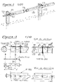
- Figure 1 is a perspective view of the most common mode of mounting a crash barrier according to the invention.
- Figure 2 shows a horizontal rail element of four meters with its characteristics as well as the connecting splice.
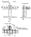
- Figure 3 shows the wooden spacer (2) encircled with galvanized iron.
- Figure 4 details in front view, bottom view and in section, the mounting of the smooth (3) of the spacer (2) on the support (1).
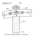
- Figure 5 shows the mounting of a safety barrier end with a grounded end.
- FIG. 1 is a perspective view of a section of slide according to the invention which is made up of galvanized iron posts (1) according to the models approved by the technical services of roads and motorways, carrying a pre-impregnated cylindrical wooden spacer and encircled by galvanized iron, itself supporting a horizontal rail made up of cylindrical elements of pre-machined reinforced wood pre-impregnated and pre-assembled in the factory, which are assembled end to end by fishplates (4), (5), (6).
- FIG. 2 shows the detail of each of the standard heald elements as it appears at the end of production, ready for assembly on site.
- Each of the elements according to the invention is composed of a wooden cylinder (3) notched with two longitudinal slits which receive in embedding the two wings of a profiled iron (9) secured by welding the ribs (4) and (5) ; this metal assembly is held integral with the wooden cylinder (3) by two TRCC 16 200 bolts (10), advantageously mounted in the factory.
- the width of the U-shaped profile will be one third of the diameter of the boom.
- Figure 3 shows the detail of each of the spacers (2) composed of a vertical wooden cylinder sectioned at a bevel at the top to allow the flow of rainwater and surrounded by a ring of galvanized iron 8 During assembly, the tightening of this collar will strengthen the cohesion of the wooden cylinder and will prevent splashes in the event of bursting under impact. The height is studied according to the invention to avoid contact with the ground.
- heald elements (3) thus described will be made integral with the following, the support (1) and the spacer (2) according to the assembly described in FIG. 4 by the TRCC bolts diameter 16 (7), (10) and (11).
- the oblong holes of the fishplates (4), (5) and (6) described in FIG. 2 allow adjustments according to the terrain, according to the curves of the roadway and according to the position of the metal supports (1).
Landscapes
- Engineering & Computer Science (AREA)
- Life Sciences & Earth Sciences (AREA)
- Wood Science & Technology (AREA)
- Architecture (AREA)
- Civil Engineering (AREA)
- Structural Engineering (AREA)
- Refuge Islands, Traffic Blockers, Or Guard Fence (AREA)
- Chemical And Physical Treatments For Wood And The Like (AREA)
- Road Paving Structures (AREA)
- Fencing (AREA)
Abstract
Description
La présente invention a pour objet des glissières de sécurité en bois ronds destinées à être placées dans tous les lieux où les véhicules sont susceptibles de s'écarter volontairement ou accidentellement des voies qui leur sont affectées, notamment le long des routes et autoroutes ou en lisière des parcs de stationnement. Le secteur technique est donc celui de la construction des dispositifs de sécurité routiers.The present invention relates to round wooden safety barriers intended to be placed in all places where vehicles are likely to deviate voluntarily or accidentally from the lanes assigned to them, in particular along roads and motorways or at the edge parking lots. The technical sector is therefore that of the construction of road safety devices.
On connaît le système mixte ayant fait l'objet d'un brevet d'invention publié sous le N° 2 663 968.We know of the mixed system which was the subject of a patent for invention published under No. 2,663,968.
La présente invention a pour objet la réalisation de lisses en bois rond armées de fer encastré alliant avantageusement les propriétés complémentaires de ces deux matériaux, d'écarteurs en bois cerclé de fer ainsi qu'un procédé de montage et de fabrication qui augmente la fiabilité des systèmes connus et diminue sensiblement le coût de fabrication, de transport et de mise en oeuvre. Il s'adapte avantageusement à toutes les situations de montage : courbes, haut de côte, fin de glissière.The present invention relates to the production of round wooden beams armed with embedded iron, advantageously combining the complementary properties of these two materials, wooden spacer rings surrounded by iron, as well as a mounting and manufacturing process which increases the reliability of the known systems and significantly reduces the cost of manufacture, transport and implementation. It adapts advantageously to all mounting situations: curves, top of hill, end of slide.
Les problèmes à résoudre sont les suivants :
- 1. Le bois est un matériau naturel hétérogène susceptible de présenter des points de moindre résistance et sous le choc d'un véhicule il plie peu, mais peut casser. Par contre le coefficient de frottement fer bois est très important et c'est une propriété qu'on mettra à profit pour freiner les véhicules.
- 2. Les supports métalliques sont inesthétiques.
- 3. Les supports métalliques doivent être écartés de la lisse pour éviter le choc avec le véhicule. Un écarteur est donc nécessaire.
- 4. Les procédés connus sont difficiles à monter et font appel à de multiples pièces. Il est donc nécessaire de simplifier et de rendre le montage polyvalent.
- 1. Wood is a heterogeneous natural material likely to present points of less resistance and under the shock of a vehicle it bends little, but can break. By cons the coefficient of iron wood friction is very important and it is a property that we will take advantage to brake vehicles.
- 2. The metal supports are unsightly.
- 3. The metal supports must be moved away from the arm to avoid impact with the vehicle. A retractor is therefore necessary.
- 4. The known methods are difficult to assemble and use multiple parts. It is therefore necessary to simplify and make the assembly versatile.
Pour résoudre ces problèmes, les solutions suivantes ont été trouvées :
- 1. Les lisses sont renforcées du côté opposé à la route par un fer profilé encastré dans la lisse bois. Les ailes du profilé sont logées dans deux fentes parallèles à l'axe de la lisse et sont ainsi invisibles.
- 2. L'écarteur est constitué d'un bois rond placé verticalement entre le support métallique et la lisse. De cette façon le support est caché mais l'écarteur s'arrête à 5 cm du sol pour éviter tout risque de pourriture. Pour les mêmes raisons l'extrémité supérieure est coupée en biais.
- 3. Pour éviter de gêner le glissement du véhicule le long de la glissière, l'écarteur peut tourner autour de l'axe du boulon de fixation. La structure est renforcée par un cerclage métallique galvanisé pour éviter tout risque de projection.
- 4. Pour faciliter le montage les éclisses métalliques de fixation opposées à la route sont solidaires du fer profilé encastré et montés en usine. Toutes les éclisses sont munies de trous oblongs permettant le montage dans toutes les situations. Selon la nécessité les éléments de la lisse horizontale seront de deux ou quatre mètres. Ils peuvent aussi être montés sur des supports existants en remplacement des glissières de sécurité métalliques, sans changer le support et éventuellement sans changer l'écarteur métallique existant.
- 1. The beams are reinforced on the side opposite the road by a profiled iron embedded in the wood beam. The wings of the profile are housed in two slots parallel to the axis of the heald and are thus invisible.
- 2. The spacer consists of a round wood placed vertically between the metal support and the rail. This way the support is hidden but the spacer stops 5 cm from the ground to avoid any risk of rot. For the same reasons the upper end is cut at an angle.
- 3. To avoid interfering with the sliding of the vehicle along the slide, the spacer can rotate around the axis of the fixing bolt. The structure is reinforced by a galvanized metal band to avoid any risk of projection.
- 4. To facilitate mounting, the metal fastening plates opposite the road are integral with the recessed profile iron and factory fitted. All fishplates are provided with oblong holes allowing mounting in all situations. Depending on the need, the elements of the horizontal rail will be two or four meters. They can also be mounted on existing supports to replace the metal safety barriers, without changing the support and possibly without changing the existing metal spacer.
Le dispositif de sécurité selon l'invention peut être mis en place avec les matériels disponibles dans les entreprises posant habituellement des glissières métalliques, sans formation particulière du personnel.The safety device according to the invention can be put in place with the materials available in companies usually installing metal slides, without special training of the personnel.
Le dispositif comporte un nombre limité de pièces standard
- piquets métalliques standard
- écarteurs bois selon invention ou standard métallique
- lisses selon invention de quatre mètres pour lignes droites et courbes ou de deux mètres pour usages spéciaux et courbes serrées.
- boulons de fixation TRCC 16 x 200 avec écrou à épaulement ou écrou et rondelle large
- éclisses de liaison courtes côté route.
- standard metal stakes
- wooden spacers according to invention or metallic standard
- smooth according to the invention of four meters for straight and curved lines or two meters for special uses and tight curves.
- fixing bolts TRCC 16 x 200 with shoulder nut or nut and large washer
- Road side short joint bars.
La description suivante se réfère aux dessins annexés qui représentent des exemples de glissière sans caractères limitatifs selon l'invention.The following description refers to the accompanying drawings which show examples of slides without limiting characters according to the invention.
La figure 1 est une vue en perspective du mode le plus courant de montage d'une glissière de sécurité selon l'invention.Figure 1 is a perspective view of the most common mode of mounting a crash barrier according to the invention.
La figure 2 représente un élément de lisse horizontale de quatre mètres avec ses caractéristiques ainsi que l'éclisse de liaison.Figure 2 shows a horizontal rail element of four meters with its characteristics as well as the connecting splice.
La figure 3 représente l'écarteur de bois (2) cerclé de fer galvanisé.Figure 3 shows the wooden spacer (2) encircled with galvanized iron.
La figure 4 détaille en vue de face, vue de dessous et en coupe, le montage de la lisse (3) de l'écarteur (2) sur le support (1).Figure 4 details in front view, bottom view and in section, the mounting of the smooth (3) of the spacer (2) on the support (1).
La figure 5 représente le montage d'une extrémité de glissière de sécurité avec un bout fiché en terre.Figure 5 shows the mounting of a safety barrier end with a grounded end.
La figure 1 est une vue en perspective d'un tronçon de glissière selon l'invention qui est composé de poteaux en fer galvanisé (1) selon les modèles agréés par les services techniques des routes et autoroutes, portant un écarteur en bois cylindrique préimprégné et cerclé de fer galvanisé, lui-même supportant une lisse horizontale constituée d'éléments cylindriques de bois armés préusinés préimprégnés et prémontés en usine, qui sont assemblés bout à bout par des éclisses (4), (5), (6).FIG. 1 is a perspective view of a section of slide according to the invention which is made up of galvanized iron posts (1) according to the models approved by the technical services of roads and motorways, carrying a pre-impregnated cylindrical wooden spacer and encircled by galvanized iron, itself supporting a horizontal rail made up of cylindrical elements of pre-machined reinforced wood pre-impregnated and pre-assembled in the factory, which are assembled end to end by fishplates (4), (5), (6).
La figure 2 donne le détail de chacun des éléments standard de lisse tel qu'il se présente à la sortie de la fabrication, prêt au montage sur site. Chacun des éléments selon l'invention est composé d'un cylindre de bois (3) entaillé de deux fentes longitudinales qui reçoivent en encastrement les deux ailes d'un fer profilé (9) solidaire par soudure des éclisses (4) et (5); cet ensemble métallique est maintenu solidaire du cylindre de bois (3) par deux boulons TRCC 16 200 (10), avantageusement monté en usine. La largeur du profilé en U sera du tiers du diamètre de la lisse.Figure 2 shows the detail of each of the standard heald elements as it appears at the end of production, ready for assembly on site. Each of the elements according to the invention is composed of a wooden cylinder (3) notched with two longitudinal slits which receive in embedding the two wings of a profiled iron (9) secured by welding the ribs (4) and (5) ; this metal assembly is held integral with the wooden cylinder (3) by two TRCC 16 200 bolts (10), advantageously mounted in the factory. The width of the U-shaped profile will be one third of the diameter of the boom.
La figure 3 montre le détail de chacun des écarteurs (2) composé d'un cylindre de bois vertical sectionné en biseau à la partie supérieure afin de permettre l'écoulement de l'eau de pluie et cerclé d'un anneau de fer galvanisé 8. Lors du montage, le serrage de ce collier permettra de renforcer la cohésion du cylindre de bois et évitera les projections en cas d'éclatement sous le choc. La hauteur est étudiée selon l'invention pour éviter le contact avec le sol.Figure 3 shows the detail of each of the spacers (2) composed of a vertical wooden cylinder sectioned at a bevel at the top to allow the flow of rainwater and surrounded by a ring of
Toutes les pièces de bois sont traitées après usinage et avant montage par injection de sels CCA classe 4 selon la norme NF B 50-100.All wood pieces are treated after machining and before assembly by injection of
Chacun des éléments de lisse (3) ainsi décrit sera rendu solidaire du suivant, du support (1) et de l'écarteur (2) selon le montage décrit à la figure 4 par les boulons TRCC diamètre 16 (7), (10) et (11). Les trous oblongs des éclisses (4), (5) et (6) décrites à la figure 2 permettent les ajustements selon le terrain, selon les courbes de la chaussée et selon la position des supports métalliques (1).Each of the heald elements (3) thus described will be made integral with the following, the support (1) and the spacer (2) according to the assembly described in FIG. 4 by the TRCC bolts diameter 16 (7), (10) and (11). The oblong holes of the fishplates (4), (5) and (6) described in FIG. 2 allow adjustments according to the terrain, according to the curves of the roadway and according to the position of the metal supports (1).
La rotation possible autour de l'axe de liaison (11) constitué par le boulon TRCC assemblant le support (1), l'écarteur (2), l'éclisse (4) d'un élément de lisse horizontale et l'éclisse (5) de l'élément suivant permet d'assurer avantageusement la réalisation des fins de glissière sans modification selon la description qui en est faite à la figure (5).The possible rotation around the connecting axis (11) constituted by the TRCC bolt assembling the support (1), the spacer (2), the splint (4) of a horizontal stringer element and the splint ( 5) of the following element advantageously ensures the realization of the end of the slide without modification according to the description which is given in Figure (5).
Claims (5)
Applications Claiming Priority (2)
| Application Number | Priority Date | Filing Date | Title |
|---|---|---|---|
| FR9205540 | 1992-04-30 | ||
| FR9205540A FR2690701B1 (en) | 1992-04-30 | 1992-04-30 | MIXED ROAD SAFETY SLIDES METAL AND ROUND WOODEN ARMS. |
Publications (2)
| Publication Number | Publication Date |
|---|---|
| EP0568456A1 true EP0568456A1 (en) | 1993-11-03 |
| EP0568456B1 EP0568456B1 (en) | 1996-03-20 |
Family
ID=9429555
Family Applications (1)
| Application Number | Title | Priority Date | Filing Date |
|---|---|---|---|
| EP93401109A Expired - Lifetime EP0568456B1 (en) | 1992-04-30 | 1993-04-28 | Guard rail made of wood and metal |
Country Status (7)
| Country | Link |
|---|---|
| US (1) | US5402987A (en) |
| EP (1) | EP0568456B1 (en) |
| AT (1) | ATE135775T1 (en) |
| CA (1) | CA2094967C (en) |
| DE (1) | DE69301857T2 (en) |
| ES (1) | ES2087676T3 (en) |
| FR (1) | FR2690701B1 (en) |
Cited By (12)
| Publication number | Priority date | Publication date | Assignee | Title |
|---|---|---|---|---|
| FR2717196A1 (en) * | 1994-03-14 | 1995-09-15 | Maussion De Jacques Frederic M | Wooden crash barrier for roads |
| FR2718473A1 (en) * | 1994-04-07 | 1995-10-13 | France Bois Impregnes Sa | Wooden safety rails attached to wooden posts for use on roads |
| FR2723755A1 (en) * | 1994-08-16 | 1996-02-23 | Sodirel | Wood and metal safety barrier for roads, esp. mountain roads |
| EP0743398A1 (en) * | 1995-05-18 | 1996-11-20 | SPIG SCHUTZPLANKEN-PRODUKTIONS-GESELLSCHAFT MBH & CO.KG | Guard rail |
| FR2735164A1 (en) * | 1995-06-06 | 1996-12-13 | Maussion Jacques Frederic Mari | Road crash barrier |
| FR2770236A1 (en) * | 1997-10-27 | 1999-04-30 | Claude Alix Georges Pomero | Road safety barrier |
| FR2793822A1 (en) * | 1999-05-21 | 2000-11-24 | Gaillard Rondino | Safety barrier for edges of road, motorway, etc., comprises T-shaped attachment linking logs to side of posts, and able to detach itself from post if shock against barrier reaches predetermined value |
| FR2834307A1 (en) * | 2001-12-28 | 2003-07-04 | Solosar | Motor road safety barrier has rail with coaxial outer cylindrical shell and solid inner core |
| FR2904837A1 (en) * | 2006-08-09 | 2008-02-15 | Profiles Du Ct Soc Par Actions | MIXED WOOD / METAL SAFETY SLIDER FOR ROADS |
| DE102007048095A1 (en) * | 2007-10-05 | 2009-04-23 | Heintzmann Sicherheitssysteme Gmbh & Co. Kg | Pole for a safety barrier |
| FR3011024A1 (en) * | 2013-09-24 | 2015-03-27 | Michel Priori | CONNECTING DEVICE BETWEEN A WOODEN PIQUET AND A TRAVERSE |
| EP2963182A2 (en) | 2014-07-04 | 2016-01-06 | Les Bois de Tertu | Method of installing a guardrail for a carriageway and guardrail obtained by said method |
Families Citing this family (18)
| Publication number | Priority date | Publication date | Assignee | Title |
|---|---|---|---|---|
| FR2765252B1 (en) * | 1997-06-27 | 1999-09-17 | Gaillard Rondino | WOODEN SAFETY SLIDES FIXED BY SPREADING ELEMENTS ON POSTS IMMOBILIZED IN THE GROUND |
| FR2796662B1 (en) * | 1999-07-22 | 2003-05-16 | Maussion Jacques De | SAFETY SLIDE FOR ROAD OR THE LIKE COMPRISING WOODEN BARS REINFORCED BY FIBERS |
| US6575434B2 (en) * | 1999-12-17 | 2003-06-10 | The Texas A&M University System | Apparatus and methods for strengthening guardrail installations |
| US6561492B1 (en) * | 2000-10-02 | 2003-05-13 | David Allen Hubbell | Wood clad guardrail assembly |
| FR2815976B1 (en) | 2000-10-30 | 2004-01-09 | Maussion Jacques De | MIXED SAFETY SLIDE METAL WOOD WITH INCREASED IMPACT RESISTANCE |
| US6530560B2 (en) | 2000-11-15 | 2003-03-11 | K.E.S.S. Inc. | Guardrail support, attachment, and positioning block |
| US6758627B2 (en) | 2000-11-15 | 2004-07-06 | K.E.S.S. Inc. | Guard rail support, attachment, and positioning spacer block |
| US6502805B2 (en) | 2001-01-05 | 2003-01-07 | David R. Lewis | Sheet-metal highway guardrail system |
| WO2002066745A1 (en) | 2001-02-19 | 2002-08-29 | Thorgeir Jonsson | Lateral load bearing structural cantilevered system such as highway guardrail and bridgerail systems |
| US6802496B1 (en) | 2002-12-09 | 2004-10-12 | John Preta | Fence bracket system and fence system using the fence bracket system |
| US7234687B2 (en) * | 2003-03-10 | 2007-06-26 | K.E.S.S. Inc. | Guardrail support, attachment, and positioning block |
| US7478796B2 (en) * | 2004-06-10 | 2009-01-20 | Monroeville Industrial Moldings, Inc. | Guardrail support members |
| US7832713B2 (en) * | 2004-07-06 | 2010-11-16 | K.E.S.S. Inc. | Guard rail mounting block and guard rail system incorporating the same |
| US8382070B1 (en) * | 2011-07-07 | 2013-02-26 | Edward L. Gibbs | Barrier system |
| KR101356566B1 (en) * | 2013-01-17 | 2014-01-29 | 주식회사 케이씨이엔지니어링 | Flexible barrier improved impact energy absorbing capacity |
| US9512633B2 (en) * | 2013-02-07 | 2016-12-06 | Best Metal Fence, LLC | Bracket attachment system |
| US10577825B1 (en) * | 2015-07-30 | 2020-03-03 | Ameristar Perimeter Security Usa Inc. | Conductive barrier |
| CA2968860C (en) | 2016-11-21 | 2024-04-23 | Simpson Strong-Tie Company, Inc. | Fence bracket |
Citations (4)
| Publication number | Priority date | Publication date | Assignee | Title |
|---|---|---|---|---|
| FR2573105A1 (en) * | 1984-11-14 | 1986-05-16 | Eynard Emile | CRASH BARRIER. |
| EP0343091A1 (en) * | 1988-05-20 | 1989-11-23 | Claude Pomero | Method and devices for keeping vehicles on the road |
| FR2658214A2 (en) * | 1984-11-14 | 1991-08-16 | Eynard Emile | Safety guard fence (crash barrier) |
| FR2663968A1 (en) * | 1990-06-27 | 1992-01-03 | Duyck Daniel | Metal/round-timber hybrid (composite) road safety barriers (safety guard fences) |
Family Cites Families (7)
| Publication number | Priority date | Publication date | Assignee | Title |
|---|---|---|---|---|
| US3776520A (en) * | 1972-11-06 | 1973-12-04 | J P C Inc | Energy absorbing highway guardrail |
| FR2633319B2 (en) * | 1984-11-14 | 1992-01-10 | Eynard Emile | IMPROVED SECURITY SLIDE |
| FR2589176B1 (en) * | 1985-10-28 | 1987-12-18 | Gaillard Rondino Cie Fse Ets | DEVICE FOR CONSTRUCTING AND ASSEMBLING WOOD SECURITY SLIDES OR BARRIERS |
| EP0228334B2 (en) * | 1985-12-23 | 1995-08-09 | Société Anonyme dite: COMPAGNIE FRANCAISE DES ETABLISSEMENTS GAILLARD | Motorway crash barriers |
| FR2623829B1 (en) * | 1987-11-27 | 1991-09-13 | Gaillard Ets | ROAD SAFETY SLIDES IN ROUND WOOD AND CONSTRUCTION METHOD |
| EP0442830A1 (en) * | 1990-02-12 | 1991-08-21 | Compagnie Francaise Des Etablissements Gaillard | Crash barrier |
| FR2681888B1 (en) * | 1991-09-30 | 1993-12-31 | Gaillard Sa Cie Fse Ets | ROAD SAFETY SLIDES COMPRISING AT LEAST ONE HORIZONTAL WOODEN RAIL. |
-
1992
- 1992-04-30 FR FR9205540A patent/FR2690701B1/en not_active Expired - Lifetime
-
1993
- 1993-04-27 CA CA002094967A patent/CA2094967C/en not_active Expired - Lifetime
- 1993-04-28 EP EP93401109A patent/EP0568456B1/en not_active Expired - Lifetime
- 1993-04-28 DE DE69301857T patent/DE69301857T2/en not_active Expired - Fee Related
- 1993-04-28 AT AT93401109T patent/ATE135775T1/en not_active IP Right Cessation
- 1993-04-28 ES ES93401109T patent/ES2087676T3/en not_active Expired - Lifetime
- 1993-04-29 US US08/055,528 patent/US5402987A/en not_active Expired - Lifetime
Patent Citations (4)
| Publication number | Priority date | Publication date | Assignee | Title |
|---|---|---|---|---|
| FR2573105A1 (en) * | 1984-11-14 | 1986-05-16 | Eynard Emile | CRASH BARRIER. |
| FR2658214A2 (en) * | 1984-11-14 | 1991-08-16 | Eynard Emile | Safety guard fence (crash barrier) |
| EP0343091A1 (en) * | 1988-05-20 | 1989-11-23 | Claude Pomero | Method and devices for keeping vehicles on the road |
| FR2663968A1 (en) * | 1990-06-27 | 1992-01-03 | Duyck Daniel | Metal/round-timber hybrid (composite) road safety barriers (safety guard fences) |
Cited By (13)
| Publication number | Priority date | Publication date | Assignee | Title |
|---|---|---|---|---|
| FR2717196A1 (en) * | 1994-03-14 | 1995-09-15 | Maussion De Jacques Frederic M | Wooden crash barrier for roads |
| FR2718473A1 (en) * | 1994-04-07 | 1995-10-13 | France Bois Impregnes Sa | Wooden safety rails attached to wooden posts for use on roads |
| FR2723755A1 (en) * | 1994-08-16 | 1996-02-23 | Sodirel | Wood and metal safety barrier for roads, esp. mountain roads |
| EP0743398A1 (en) * | 1995-05-18 | 1996-11-20 | SPIG SCHUTZPLANKEN-PRODUKTIONS-GESELLSCHAFT MBH & CO.KG | Guard rail |
| FR2735164A1 (en) * | 1995-06-06 | 1996-12-13 | Maussion Jacques Frederic Mari | Road crash barrier |
| FR2770236A1 (en) * | 1997-10-27 | 1999-04-30 | Claude Alix Georges Pomero | Road safety barrier |
| FR2793822A1 (en) * | 1999-05-21 | 2000-11-24 | Gaillard Rondino | Safety barrier for edges of road, motorway, etc., comprises T-shaped attachment linking logs to side of posts, and able to detach itself from post if shock against barrier reaches predetermined value |
| WO2000071820A1 (en) * | 1999-05-21 | 2000-11-30 | Gaillard Rondino | Safety wooden barrier supported on variable centrelines |
| FR2834307A1 (en) * | 2001-12-28 | 2003-07-04 | Solosar | Motor road safety barrier has rail with coaxial outer cylindrical shell and solid inner core |
| FR2904837A1 (en) * | 2006-08-09 | 2008-02-15 | Profiles Du Ct Soc Par Actions | MIXED WOOD / METAL SAFETY SLIDER FOR ROADS |
| DE102007048095A1 (en) * | 2007-10-05 | 2009-04-23 | Heintzmann Sicherheitssysteme Gmbh & Co. Kg | Pole for a safety barrier |
| FR3011024A1 (en) * | 2013-09-24 | 2015-03-27 | Michel Priori | CONNECTING DEVICE BETWEEN A WOODEN PIQUET AND A TRAVERSE |
| EP2963182A2 (en) | 2014-07-04 | 2016-01-06 | Les Bois de Tertu | Method of installing a guardrail for a carriageway and guardrail obtained by said method |
Also Published As
| Publication number | Publication date |
|---|---|
| EP0568456B1 (en) | 1996-03-20 |
| ATE135775T1 (en) | 1996-04-15 |
| US5402987A (en) | 1995-04-04 |
| DE69301857D1 (en) | 1996-04-25 |
| DE69301857T2 (en) | 1996-10-02 |
| CA2094967A1 (en) | 1993-10-31 |
| CA2094967C (en) | 2001-08-28 |
| FR2690701B1 (en) | 1996-09-20 |
| FR2690701A1 (en) | 1993-11-05 |
| ES2087676T3 (en) | 1996-07-16 |
Similar Documents
| Publication | Publication Date | Title |
|---|---|---|
| EP0568456B1 (en) | Guard rail made of wood and metal | |
| EP0343091B1 (en) | Method and devices for keeping vehicles on the road | |
| EP0886702B1 (en) | Crash barrier, method for erecting same, and machine therefor | |
| EP0228334B2 (en) | Motorway crash barriers | |
| US5184800A (en) | Portable snow fence system | |
| EP0379424A2 (en) | Road safety barrier | |
| EP0184525B1 (en) | Crash barrier | |
| KR102347678B1 (en) | Bracket Of Design Type Fence For Easy angle adjustment | |
| RU87007U1 (en) | VEHICLE FORCED STOP | |
| FR3071856B1 (en) | BARRIER ANTI CAR BELIER | |
| EP1337714A1 (en) | Protective barrier, in particular in mountain site | |
| FR2660333A1 (en) | Panel to be fixed on protective or safety barriers, forming a multipurpose passive protection | |
| FR2646456A1 (en) | Shelter arrangement for pedestrians | |
| US5575121A (en) | Sound barrier wall construction using tire sections | |
| EP0604277B1 (en) | Guide rails with indeformable supports and at least one horizontal deformable continuous guide member | |
| FR2551784A3 (en) | Sound-proofing wall. The invention relates to a sound-proofing wall, in particular for providing protection from sound along traffic lanes, which comprises posts, placed at a distance from one another along the lane and having a substantially I-shaped cross-section, and wall elements disposed between them. Each post is formed from two T-shaped profiles 1, 2 made by extruding aluminium or a similar material, whose median flanges 5 are facing each other and which are connected to each other by at least one cross-piece 3; the free ends of the median flanges comprise on both sides means 9 for a fixing by fitting or attachment of a fixing profile 10 made by extruding aluminium or similar material; each wall element 4 is clamped between a flange oriented perpendicular to the cross-piece of the fixing profile 10 and a flange 6 of the post oriented parallel to the previously mentioned flange. | |
| FR2735164A1 (en) | Road crash barrier | |
| KR101898252B1 (en) | End Structure of Guard Rail and its Construction Method | |
| EP3162962B1 (en) | Signalling mast with polygonal cross-section having perforated surfaces | |
| FR2479301A1 (en) | PROTECTIVE EDGE PROVIDED WITH AT LEAST ONE SLIDE BAR | |
| EP1767701A1 (en) | Method for absorbing an impact against a road safety barrier and safety barrier implemented accordingly | |
| SE544956C2 (en) | Guiderail for a roadway barrier system | |
| FR3011024A1 (en) | CONNECTING DEVICE BETWEEN A WOODEN PIQUET AND A TRAVERSE | |
| FR2663968A1 (en) | Metal/round-timber hybrid (composite) road safety barriers (safety guard fences) | |
| WO2022161956A1 (en) | Security bollard system, installation and method |
Legal Events
| Date | Code | Title | Description |
|---|---|---|---|
| PUAI | Public reference made under article 153(3) epc to a published international application that has entered the european phase |
Free format text: ORIGINAL CODE: 0009012 |
|
| AK | Designated contracting states |
Kind code of ref document: A1 Designated state(s): AT BE CH DE DK ES GB IE IT LI LU NL SE |
|
| 17P | Request for examination filed |
Effective date: 19940429 |
|
| 17Q | First examination report despatched |
Effective date: 19950718 |
|
| GRAH | Despatch of communication of intention to grant a patent |
Free format text: ORIGINAL CODE: EPIDOS IGRA |
|
| GRAA | (expected) grant |
Free format text: ORIGINAL CODE: 0009210 |
|
| AK | Designated contracting states |
Kind code of ref document: B1 Designated state(s): AT BE CH DE DK ES GB IE IT LI LU NL SE |
|
| PG25 | Lapsed in a contracting state [announced via postgrant information from national office to epo] |
Ref country code: DK Effective date: 19960320 |
|
| REF | Corresponds to: |
Ref document number: 135775 Country of ref document: AT Date of ref document: 19960415 Kind code of ref document: T |
|
| REG | Reference to a national code |
Ref country code: IE Ref legal event code: FG4D Free format text: 67681 |
|
| REF | Corresponds to: |
Ref document number: 69301857 Country of ref document: DE Date of ref document: 19960425 |
|
| ITF | It: translation for a ep patent filed |
Owner name: DE DOMINICIS & MAYER S.R.L. |
|
| REG | Reference to a national code |
Ref country code: CH Ref legal event code: NV Representative=s name: BOVARD AG PATENTANWAELTE |
|
| REG | Reference to a national code |
Ref country code: ES Ref legal event code: BA2A Ref document number: 2087676 Country of ref document: ES Kind code of ref document: T3 |
|
| GBT | Gb: translation of ep patent filed (gb section 77(6)(a)/1977) |
Effective date: 19960522 |
|
| PG25 | Lapsed in a contracting state [announced via postgrant information from national office to epo] |
Ref country code: SE Effective date: 19960620 |
|
| REG | Reference to a national code |
Ref country code: ES Ref legal event code: FG2A Ref document number: 2087676 Country of ref document: ES Kind code of ref document: T3 |
|
| PLBE | No opposition filed within time limit |
Free format text: ORIGINAL CODE: 0009261 |
|
| STAA | Information on the status of an ep patent application or granted ep patent |
Free format text: STATUS: NO OPPOSITION FILED WITHIN TIME LIMIT |
|
| 26N | No opposition filed | ||
| REG | Reference to a national code |
Ref country code: GB Ref legal event code: IF02 |
|
| PGFP | Annual fee paid to national office [announced via postgrant information from national office to epo] |
Ref country code: AT Payment date: 20050413 Year of fee payment: 13 |
|
| PG25 | Lapsed in a contracting state [announced via postgrant information from national office to epo] |
Ref country code: AT Free format text: LAPSE BECAUSE OF NON-PAYMENT OF DUE FEES Effective date: 20060428 |
|
| PGFP | Annual fee paid to national office [announced via postgrant information from national office to epo] |
Ref country code: LU Payment date: 20070418 Year of fee payment: 15 |
|
| PGFP | Annual fee paid to national office [announced via postgrant information from national office to epo] |
Ref country code: NL Payment date: 20070430 Year of fee payment: 15 Ref country code: DE Payment date: 20070430 Year of fee payment: 15 |
|
| PGFP | Annual fee paid to national office [announced via postgrant information from national office to epo] |
Ref country code: CH Payment date: 20080428 Year of fee payment: 16 |
|
| PGFP | Annual fee paid to national office [announced via postgrant information from national office to epo] |
Ref country code: BE Payment date: 20080513 Year of fee payment: 16 |
|
| PGFP | Annual fee paid to national office [announced via postgrant information from national office to epo] |
Ref country code: IE Payment date: 20080430 Year of fee payment: 16 |
|
| PGFP | Annual fee paid to national office [announced via postgrant information from national office to epo] |
Ref country code: GB Payment date: 20080430 Year of fee payment: 16 |
|
| NLV4 | Nl: lapsed or anulled due to non-payment of the annual fee |
Effective date: 20081101 |
|
| PG25 | Lapsed in a contracting state [announced via postgrant information from national office to epo] |
Ref country code: NL Free format text: LAPSE BECAUSE OF NON-PAYMENT OF DUE FEES Effective date: 20081101 Ref country code: DE Free format text: LAPSE BECAUSE OF NON-PAYMENT OF DUE FEES Effective date: 20081101 |
|
| BERE | Be: lapsed |
Owner name: *DE MAUSSION JACQUES Effective date: 20090430 Owner name: *DUYCK DANIEL Effective date: 20090430 |
|
| REG | Reference to a national code |
Ref country code: CH Ref legal event code: PL |
|
| GBPC | Gb: european patent ceased through non-payment of renewal fee |
Effective date: 20090428 |
|
| PG25 | Lapsed in a contracting state [announced via postgrant information from national office to epo] |
Ref country code: LI Free format text: LAPSE BECAUSE OF NON-PAYMENT OF DUE FEES Effective date: 20090430 Ref country code: CH Free format text: LAPSE BECAUSE OF NON-PAYMENT OF DUE FEES Effective date: 20090430 |
|
| REG | Reference to a national code |
Ref country code: IE Ref legal event code: MM4A |
|
| PG25 | Lapsed in a contracting state [announced via postgrant information from national office to epo] |
Ref country code: IE Free format text: LAPSE BECAUSE OF NON-PAYMENT OF DUE FEES Effective date: 20090428 Ref country code: GB Free format text: LAPSE BECAUSE OF NON-PAYMENT OF DUE FEES Effective date: 20090428 |
|
| PG25 | Lapsed in a contracting state [announced via postgrant information from national office to epo] |
Ref country code: BE Free format text: LAPSE BECAUSE OF NON-PAYMENT OF DUE FEES Effective date: 20090430 |
|
| PG25 | Lapsed in a contracting state [announced via postgrant information from national office to epo] |
Ref country code: LU Free format text: LAPSE BECAUSE OF NON-PAYMENT OF DUE FEES Effective date: 20080428 |
|
| PGFP | Annual fee paid to national office [announced via postgrant information from national office to epo] |
Ref country code: IT Payment date: 20120420 Year of fee payment: 20 |
|
| PGFP | Annual fee paid to national office [announced via postgrant information from national office to epo] |
Ref country code: ES Payment date: 20120530 Year of fee payment: 20 |
|
| REG | Reference to a national code |
Ref country code: ES Ref legal event code: FD2A Effective date: 20130718 |
|
| PG25 | Lapsed in a contracting state [announced via postgrant information from national office to epo] |
Ref country code: ES Free format text: LAPSE BECAUSE OF EXPIRATION OF PROTECTION Effective date: 20130429 |