EP0566853A2 - Méthode et dispositif pour le dressage d'une meule - Google Patents
Méthode et dispositif pour le dressage d'une meule Download PDFInfo
- Publication number
- EP0566853A2 EP0566853A2 EP93103767A EP93103767A EP0566853A2 EP 0566853 A2 EP0566853 A2 EP 0566853A2 EP 93103767 A EP93103767 A EP 93103767A EP 93103767 A EP93103767 A EP 93103767A EP 0566853 A2 EP0566853 A2 EP 0566853A2
- Authority
- EP
- European Patent Office
- Prior art keywords
- grinding wheel
- dressing
- grinding
- dresser
- workpiece
- Prior art date
- Legal status (The legal status is an assumption and is not a legal conclusion. Google has not performed a legal analysis and makes no representation as to the accuracy of the status listed.)
- Withdrawn
Links
Images


Classifications
-
- B—PERFORMING OPERATIONS; TRANSPORTING
- B24—GRINDING; POLISHING
- B24B—MACHINES, DEVICES, OR PROCESSES FOR GRINDING OR POLISHING; DRESSING OR CONDITIONING OF ABRADING SURFACES; FEEDING OF GRINDING, POLISHING, OR LAPPING AGENTS
- B24B49/00—Measuring or gauging equipment for controlling the feed movement of the grinding tool or work; Arrangements of indicating or measuring equipment, e.g. for indicating the start of the grinding operation
- B24B49/18—Measuring or gauging equipment for controlling the feed movement of the grinding tool or work; Arrangements of indicating or measuring equipment, e.g. for indicating the start of the grinding operation taking regard of the presence of dressing tools
-
- B—PERFORMING OPERATIONS; TRANSPORTING
- B24—GRINDING; POLISHING
- B24B—MACHINES, DEVICES, OR PROCESSES FOR GRINDING OR POLISHING; DRESSING OR CONDITIONING OF ABRADING SURFACES; FEEDING OF GRINDING, POLISHING, OR LAPPING AGENTS
- B24B53/00—Devices or means for dressing or conditioning abrasive surfaces
-
- G—PHYSICS
- G05—CONTROLLING; REGULATING
- G05B—CONTROL OR REGULATING SYSTEMS IN GENERAL; FUNCTIONAL ELEMENTS OF SUCH SYSTEMS; MONITORING OR TESTING ARRANGEMENTS FOR SUCH SYSTEMS OR ELEMENTS
- G05B2219/00—Program-control systems
- G05B2219/30—Nc systems
- G05B2219/37—Measurements
- G05B2219/37339—Eccentricity, cylindricity, circularity
-
- G—PHYSICS
- G05—CONTROLLING; REGULATING
- G05B—CONTROL OR REGULATING SYSTEMS IN GENERAL; FUNCTIONAL ELEMENTS OF SUCH SYSTEMS; MONITORING OR TESTING ARRANGEMENTS FOR SUCH SYSTEMS OR ELEMENTS
- G05B2219/00—Program-control systems
- G05B2219/30—Nc systems
- G05B2219/37—Measurements
- G05B2219/37345—Dimension of workpiece, diameter
-
- G—PHYSICS
- G05—CONTROLLING; REGULATING
- G05B—CONTROL OR REGULATING SYSTEMS IN GENERAL; FUNCTIONAL ELEMENTS OF SUCH SYSTEMS; MONITORING OR TESTING ARRANGEMENTS FOR SUCH SYSTEMS OR ELEMENTS
- G05B2219/00—Program-control systems
- G05B2219/30—Nc systems
- G05B2219/49—Nc machine tool, till multiple
- G05B2219/49247—Dressing started after number of workpieces machined
-
- G—PHYSICS
- G05—CONTROLLING; REGULATING
- G05B—CONTROL OR REGULATING SYSTEMS IN GENERAL; FUNCTIONAL ELEMENTS OF SUCH SYSTEMS; MONITORING OR TESTING ARRANGEMENTS FOR SUCH SYSTEMS OR ELEMENTS
- G05B2219/00—Program-control systems
- G05B2219/30—Nc systems
- G05B2219/49—Nc machine tool, till multiple
- G05B2219/49248—Dressing started if sparking out time to get correct surface is too long
Definitions
- the present invention relates to a method and an apparatus for dressing a grinding wheel.
- grinding ability of a grinding wheel becomes worse during a grinding operation for workpiece, thereby lowering the grinding efficiency and the grinding accuracy. It is thus necessary that the grinding wheel is dressed at suitable time intervals so as to restore the grinding ability. Further, as the diameter of the grinding wheel becomes small by grinding the workpiece or being dressed, the sharpness of the grinding wheel lowers rapidly. Therefore, the grinding wheel has to be dressed at intervals which are changed in response to the diameter of the grinding wheel.
- the diameter of the grinding wheel is measured and the dressing intervals are shortened in response to decrease of the measured diameter. Further, in the dressing apparatus disclosed in Japanese Laid-Open Patent Publication No. 54-101591, as the number of times of the dressing operations increases, the number of the workpieces which can be ground after each dressing operation is decreased, whereby the dressing intervals are changed in response to the diameter of the grinding wheel.
- the former apparatus requires the device for measuring the diameter of the grinding wheel. Also, since such as CBN grinding wheel is worn out slowly, it is impossible to sufficiently restore the grinding ability of the grinding wheel by changing the dressing intervals in response to the diameter of the grinding wheel.
- both of the conventional apparatus do not detect the sharpness of the grinding wheel directly, it is impossible to dress the grinding wheel at optimal intervals. Namely, since lowering of the sharpness of the grinding wheel depends on grinding conditions such as a material of the workpiece and a circumferential speed of the grinding wheel, the interval between every two successive dressing operations should be changed according to the grinding conditions.
- the dressing apparatus disclosed in Japanese Laid-Open Patent Publication No. 54-101591 decides the intervals between every two successive dressing operations by calculation. Therefore, the grinding wheel can not be dressed at optimal intervals.
- Another object of the present invention is to provide an improved method and apparatus which detect lowering of sharpness of the grinding wheel and dress the grinding wheel when the sharpness becomes less than a predetermined value.
- a method of dressing a grinding wheel comprises the steps of measuring a circularity (roundness) of a cylindrical workpiece ground by the grinding wheel, detecting the length of time period in which the circularity becomes a predetermined allowable value, judging whether or not the detected time length exceeds a first setting time, and dressing the grinding wheel using the dresser when the detected time length exceeds the first setting time.
- an apparatus for dressing a grinding surface of a grinding wheel by a dresser comprises means for measuring a radial dimension of a cylindrical workpiece ground by the grinding wheel, means for measuring a circularity of the workpiece based upon the measured dimension of the workpiece, means for detecting the length of time period in which the circularity becomes a predetermined allowable value, means for judging whether or not the detected time length exceeds a first setting time, and means for starting a dressing operation using the dresser when the detected time length exceeds the first setting time.
- the length of time period in which the circularity of the workpiece ground by the grinding wheel reaches the allowable value becomes long in proportion to the lowering of the sharpness of the grinding wheel.
- the grinding wheel is dressed by a dresser. Accordingly, the dressing intervals are determined independently of a diameter and a material of the grinding wheel, thereby carrying out optimal dressing operation in consideration of the lowering of the sharpness of the grinding wheel.
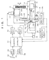
- FIG. 1 shows the overall structure of a cylindrical grinding machine which has an apparatus for dressing a grinding wheel according to the present invention.
- numeral 10 denotes a grinding machine
- numeral 21 denotes a numerical controller for controlling the grinding machine 10.
- the grinding machine 10 is provided with a wheel head 12 guided on a bed 11 for movement in Z-axis direction, and a workpiece table 14 guided on the bed 11 for movement in X-axis direction perpendicular to the Z-axis direction.
- the wheel head 12 is moved by a servomotor 13 while the workpiece table 14 is moved by a servomotor 15.
- the wheel head 12 is provided with a wheel spindle 122 carrying a grinding wheel 121 and a drive motor 124 which rotates the grinding wheel 121 via a rotational movement transmitting mechanism 123.
- a spindle head 16 and a tailstock 17 are coaxially mounted to oppose each other. Both ends of a cylindrical workpiece W are supported by a center 16b attached to a main spindle 16a of the spindle head 16 and a center 17a of the tailstock 17.
- the spindle head 16 has a spindle motor (not shown).
- a pin 18 connects the main spindle 16a and the workpiece W and transmits torque from the spindle motor to the workpiece W.
- a measuring device 19 Disposed on the bed 11 is a measuring device 19 for measuring a diameter of the workpiece W ground by the grinding wheel 121. Further, the spindle head 16 is further provided with a dresser 20 for dressing a grinding surface of the grinding wheel 121.
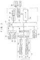
- the numerical controller 21 is composed of a main central processing unit 21 (hereinafter referred to as "main CPU") for controlling entire of the grinding machine; a ROM 23; a RAM 24 for storing a machining program, a dressing program and other data; a drive CPU 26 connected to the main CPU 22 via a RAM 25; a pulse generation circuit 27 for generating pulse signals in response to command signals output from the drive CPU 26; an A/D converter 28 which converts measured values into digital signals; and an interface 29.
- main CPU main central processing unit 21
- the pulse generation circuit 27 is connected to the servomotors 13 and 15 via a drive unit 30 for Z-axis and a drive unit 31 for X-axis, respectively.
- the interface 29 is connected to a tape reader 33 for reading signs written on a punched tape 32, and a keyboard 34 through which the machining program, other data and various operation commands are input.
- Numeral 35 denotes a CRT which displays input data and various messages including a message indicating the occurrence of an abnormality.
- a machining program and a dressing program are input to the CPU 22 through the tape reader 33 in advance and stored in the RAM 24.
- the measuring device 19 is composed of a pair of probes 19a which are contactable with an outer peripheral surface of the workpiece W, a pair of differential transformers 19b by which mechanical displacements of the probes 19a are converted to electrical signals, a pair of amplifiers 19c for amplifying signals output from the differential transformers 19b, and an adding circuit 19d which adds the signals amplified at the amplifiers 19c and output a diameter signal to the A/D converter 28, as shown in FIGs. 1 and 2. This diameter signal indicates the measured diameter of the workpiece.
- the measuring device 19 is arranged to be movable in V-axis direction shown in FIG. 1 by an actuator having a cylinder (not shown) and the like.
- a circularity measuring circuit 36 is further provided for measuring a circularity of the workpiece W based upon the signal output from the measuring device 19. Namely, the signal output from one of the amplifiers 19c, which represents radius of the workpiece W, is input to the circularity measuring circuit 36. Then, the circularity is obtained based upon the difference between the maximum value and minimum value of the signal within each revolution.
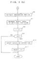
- FIG. 3(a) is a main-routine of a grinding program for controlling a grinding operation.
- processing of the main routine is started, at step S1, one command of the machining program is fetched from the RAM 25 so that the wheel head 12 is advanced at rapid speed.
- the drive CPU 26 operates in response to the fetched command and the pulse generation circuit 27 outputs the pulse signals corresponding to the predetermined rapid feed amount.
- the pulse signals are supplied to the drive unit 30 so as to drive the servomotor 13.
- the wheel head 12 is then advanced at rapid feed speed.
- step S2 a next command is fetched from the RAM 25 so that the wheel head 12 is advanced at a rough grinding feed speed by the processing similar to the above-described rapid feed.
- the grinding wheel 121 is contacted with the workpiece W and the grinding operation is started.
- the processing proceeds to step S3.
- step S3 the measuring device 19 is advanced toward the workpiece W until the probes 19 are engaged with the outer peripheral surface of the workpiece W.
- step S4 the wheel head 12 is advanced at a fine grinding feed speed. In the fine grinding feed, the signals output from the measuring device 19 is used. When the diameter of the workpiece W measured by the measuring device 19 becomes a finishing diameter, the wheel head 12 is stopped. Thereafter, the processing proceeds to step S5 at which spark-out is executed.
- the spark-out step is illustrated in detail in FIG. 4.
- a timer is started for measuring a time length of the spark-out grinding.
- the signal output from the circularity measuring circuit 36 is input in the CPU 22 to judge whether or not the circularity of the workpiece is within an allowable value.
- the processing proceeds to step S22.
- the processing proceeds to step S25.
- the first setting time T1 is determined by following method. At first, the workpiece W is ground by the grinding wheel whose sharpness is lowered to the extent which needs the dressing operation. Subsequently, the length of the time period necessary for the circularity to become less than the allowable value by the spark-out is measured. Then, a time shorter than the measured time length by a predetermined time is used as the first setting time T1.
- step S22 When it is judged at step S22 that the time length measured by the timer exceeds the first setting time T1, the processing proceeds to step S23.
- step S23 parameter i representing the number of the workpieces which have been ground after last dressing operation is set to f. As described hereinafter, when the parameter i is set to f, the grinding wheel 121 is dressed. Then, at step S24, the timer is stopped and then the processing returns to the main-routine.
- step S24 When it is judged at step S22 that the time length measured by the timer does not exceed the first setting time T1, the processing proceeds to step S24.
- step S25 it is judged whether or not the time length measured by the timer exceeds second setting time T2 for finding abnormality.
- the processing returns to step S21 at which it is judged again that whether or not the circularity reaches the allowable value.
- step S26 the processing proceeds to step S26 at which the occurrence of an abnormal condition is informed to an operator through the CRT 35.
- step S6 When the processing returns from step S24 to the main-routine shown, the measuring device 19 is retracted to its retracted position at step S6. At next step S7, the wheel head 12 is retracted to its original position. At step S8, the parameter i representing the number of the workpieces which have been ground is increased by one. At step S9, it is judged that whether or not the parameter i is equal to or larger than f. This value f is set in proportion to the number of the workpiece which can be ground between the last dressing operation and the next dressing operation. When it is judged at step S9 that the parameter i is equal to or larger than f, the processing proceeds to step S10.
- the parameter i is set to f at step S23, whereby the processing proceeds to step S10.
- the workpiece table 14 and the wheel head 12 are moved according to the dressing program so that the grinding wheel 121 is dressed by the dresser 20.
- the parameter i representing the number of the workpieces which have been ground is reset to zero.
- the length of time period in which the circularity of the workpiece reaches the allowable value is measured by the timer during the spark-out grinding.
- the grinding wheel is dressed by a dresser.
- the grinding wheel is dressed at optimal dressing intervals independently of a diameter and a material of the grinding wheel. Further, it is possible to detect the sharpness of the grinding wheel accurately without the use of a sensor and the like. This prevents the grinding wheel from being dressed more than is necessary.
- the number of the workpieces which can be machined by one grinding wheel also increases and the whole machining cost including dressing cost is decreased.
- the method and apparatus of the present invention can be adapted in the method and apparatus for truing the grinding wheel using a truer.
- An apparatus for dressing a grinding surface of a grinding wheel by a dresser comprises means for measuring a diameter of a cylindrical workpiece ground by the grinding wheel, means for measuring a circularity of the workpiece based upon the measured diameter of the workpiece, means for detecting length of time period in which the circularity becomes a predetermined allowable value, means for judging whether or not the detected time length exceeds a first setting time, and means for starting a dressing operation using the dresser when the detected time length exceeds the first setting time. Likewise, when the number of the workpieces which have been ground after last dressing operation becomes a preset value, the grinding wheel is dressed by the dresser.
Landscapes
- Engineering & Computer Science (AREA)
- Mechanical Engineering (AREA)
- Grinding-Machine Dressing And Accessory Apparatuses (AREA)
- Constituent Portions Of Griding Lathes, Driving, Sensing And Control (AREA)
Applications Claiming Priority (2)
| Application Number | Priority Date | Filing Date | Title |
|---|---|---|---|
| JP6851192A JPH05277934A (ja) | 1992-03-26 | 1992-03-26 | 研削砥石のドレッシング制御装置 |
| JP68511/92 | 1992-03-26 |
Publications (2)
| Publication Number | Publication Date |
|---|---|
| EP0566853A2 true EP0566853A2 (fr) | 1993-10-27 |
| EP0566853A3 EP0566853A3 (fr) | 1994-03-30 |
Family
ID=13375817
Family Applications (1)
| Application Number | Title | Priority Date | Filing Date |
|---|---|---|---|
| EP93103767A Withdrawn EP0566853A2 (fr) | 1992-03-26 | 1993-03-09 | Méthode et dispositif pour le dressage d'une meule |
Country Status (2)
| Country | Link |
|---|---|
| EP (1) | EP0566853A2 (fr) |
| JP (1) | JPH05277934A (fr) |
Cited By (4)
| Publication number | Priority date | Publication date | Assignee | Title |
|---|---|---|---|---|
| EP0742078A1 (fr) | 1995-05-12 | 1996-11-13 | BALANCE SYSTEMS S.r.l. | Motorisation, dispositif de contrÔle et procédé associé pour une rectifieuse |
| EP1221356A1 (fr) * | 2001-01-05 | 2002-07-10 | Nidek Co., Ltd. | Dispositif de meulage pour verres ophtalmiques |
| CN101590619B (zh) * | 2008-05-30 | 2013-06-26 | 无锡上机数控股份有限公司 | 一种数控曲轴曲拐外圆磨床 |
| CN113524039A (zh) * | 2021-07-28 | 2021-10-22 | 大连理工大学 | 一种用于数控磨床的砂轮轮廓在位测量装置及方法 |
Citations (2)
| Publication number | Priority date | Publication date | Assignee | Title |
|---|---|---|---|---|
| JPS54101591A (en) * | 1978-01-26 | 1979-08-10 | Koyo Seiko Co Ltd | Commanding device for dressing grinding wheel |
| EP0225077A2 (fr) * | 1985-11-20 | 1987-06-10 | Ex-Cell-O Corporation | Machine à meuler superabrasive avec une période de meulage et des instants de dressage variables |
-
1992
- 1992-03-26 JP JP6851192A patent/JPH05277934A/ja active Pending
-
1993
- 1993-03-09 EP EP93103767A patent/EP0566853A2/fr not_active Withdrawn
Patent Citations (2)
| Publication number | Priority date | Publication date | Assignee | Title |
|---|---|---|---|---|
| JPS54101591A (en) * | 1978-01-26 | 1979-08-10 | Koyo Seiko Co Ltd | Commanding device for dressing grinding wheel |
| EP0225077A2 (fr) * | 1985-11-20 | 1987-06-10 | Ex-Cell-O Corporation | Machine à meuler superabrasive avec une période de meulage et des instants de dressage variables |
Non-Patent Citations (3)
| Title |
|---|
| DATABASE INSPEC INSTITUTE OF ELECTRICAL ENGINEERS, STEVENAGE, GB Inspec No. 960115 June 1976, INOUE 'analysis of grinding behavior for controlling grinding cycle' & JOURNAL OF JAPAN SOCIETY OF PRECISION ENGINEERING vol. 42, no. 6 , February 1976 , JAPAN pages 471 - 477 * |
| PATENT ABSTRACTS OF JAPAN vol. 3, no. 126 (M-77)20 October 1979 & JP-A-54 101 591 (KOYO SEIKO) 8 October 1979 * |
| TRANSACTIONS OF THE AMERICAN SOCIETY OF MECHANICAL ENGINEERS, SERIES B: JOURNAL OF ENGINEERING FOR INDUSTRY vol. 106, no. 1 , February 1984 , NEW YORK US pages 70 - 74 MALKIN 'optimal infeed control for accelerated spark-out in plunge grinding' * |
Cited By (6)
| Publication number | Priority date | Publication date | Assignee | Title |
|---|---|---|---|---|
| EP0742078A1 (fr) | 1995-05-12 | 1996-11-13 | BALANCE SYSTEMS S.r.l. | Motorisation, dispositif de contrÔle et procédé associé pour une rectifieuse |
| US5741172A (en) * | 1995-05-12 | 1998-04-21 | Balance Systems S.R.L. | Drive and control device and related process for a grinding machine |
| EP1221356A1 (fr) * | 2001-01-05 | 2002-07-10 | Nidek Co., Ltd. | Dispositif de meulage pour verres ophtalmiques |
| US6592431B2 (en) | 2001-01-05 | 2003-07-15 | Nidex Co., Ltd. | Eyeglass lens processing apparatus |
| CN101590619B (zh) * | 2008-05-30 | 2013-06-26 | 无锡上机数控股份有限公司 | 一种数控曲轴曲拐外圆磨床 |
| CN113524039A (zh) * | 2021-07-28 | 2021-10-22 | 大连理工大学 | 一种用于数控磨床的砂轮轮廓在位测量装置及方法 |
Also Published As
| Publication number | Publication date |
|---|---|
| JPH05277934A (ja) | 1993-10-26 |
| EP0566853A3 (fr) | 1994-03-30 |
Similar Documents
| Publication | Publication Date | Title |
|---|---|---|
| JP2750499B2 (ja) | Nc研削盤における超砥粒砥石のドレッシング確認方法 | |
| US4551950A (en) | Truing apparatus for a grinding wheel with rounded corners | |
| EP0352635B1 (fr) | Rectifieuse à commande numérique | |
| JPS62176758A (ja) | 超研摩研削加工方法と研削盤 | |
| US3964210A (en) | Grinding apparatus | |
| JP2004534664A (ja) | 工作機械の加工プロセスの検査装置と検査方法 | |
| US4731954A (en) | Method and apparatus for initiating an operation for dressing a grinding wheel in conformity with its degree of bluntness | |
| US4905417A (en) | Numerical control grinding machine | |
| EP0566853A2 (fr) | Méthode et dispositif pour le dressage d'une meule | |
| EP0505836A2 (fr) | Méthode et dispositif pour le dressage d'une meule à profil angulaire | |
| US4711054A (en) | Grinding machine with a steady rest | |
| JPS62188646A (ja) | 工作機械における機械加工品の機械加工を制御する方法および装置 | |
| EP0356663A2 (fr) | Rectifieuse ainsi que procédé et dispositif de contrôle de l'opération de rectification | |
| EP0521383A1 (fr) | Procédé et dispositif pour la rectification cylindrique de pièces | |
| JPH08257905A (ja) | 自動定寸装置 | |
| JPH1177491A (ja) | 工具を用いる加工装置 | |
| JP2565032Y2 (ja) | 研削盤のドレスインターバル制御装置 | |
| JPH04354673A (ja) | 平面研削盤の制御方法 | |
| JP3210704B2 (ja) | 研削盤およびトラバース研削方法 | |
| JP2949593B2 (ja) | ワークの円筒度検出装置 | |
| JP3050712B2 (ja) | ギアホーニング加工方法 | |
| JP3168767B2 (ja) | 研削装置 | |
| JP3300384B2 (ja) | 研削盤の制御方法 | |
| JPH01252358A (ja) | 撓み検知手段付スピンドル装置を備えた研削加工装置の制御方法 | |
| JP3348561B2 (ja) | 研削加工におけるギャップ測定方法および装置 |
Legal Events
| Date | Code | Title | Description |
|---|---|---|---|
| PUAI | Public reference made under article 153(3) epc to a published international application that has entered the european phase |
Free format text: ORIGINAL CODE: 0009012 |
|
| AK | Designated contracting states |
Kind code of ref document: A2 Designated state(s): DE FR GB |
|
| PUAL | Search report despatched |
Free format text: ORIGINAL CODE: 0009013 |
|
| AK | Designated contracting states |
Kind code of ref document: A3 Designated state(s): DE FR GB |
|
| STAA | Information on the status of an ep patent application or granted ep patent |
Free format text: STATUS: THE APPLICATION IS DEEMED TO BE WITHDRAWN |
|
| 18D | Application deemed to be withdrawn |
Effective date: 19941001 |